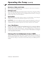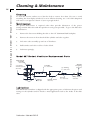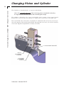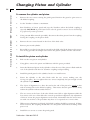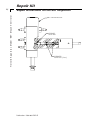
1
Model ‘687’
Mouse Ventilator
User’s Manual
‘687’ Mouse Ventilator
MA1 55-0001
Publication 5396-001-REV-E
WEEE/RoHS Compliance Statement
EU Directives WEEE and RoHS
To Our Valued Customers:
We are committed to being a good corporate citizen. As part of that commitment,
we strive to maintain an environmentally conscious manufacturing operation. The
European Union (EU) has enacted two Directives, the first on product recycling
(Waste Electrical and Electronic Equipment, WEEE) and the second limiting the use
of certain substances (Restriction on the use of Hazardous Substances, RoHS).
Over time, these Directives will be implemented in the national laws of each EU
Member State.
Once the final national regulations have been put into place, recycling will be offered
for our products which are within the scope of the WEEE Directive. Products falling
under the scope of the WEEE Directive available for sale after August 13, 2005 will
be identified with a “wheelie bin” symbol.
Two Categories of products covered by the WEEE Directive are currently exempt
from the RoHS Directive – Category 8, medical devices (with the exception of
implanted or infected products) and Category 9, monitoring and control instruments.
Most of our products fall into either Category 8 or 9 and are currently exempt from
the RoHS Directive. We will continue to monitor the application of the RoHS
Directive to its products and will comply with any changes as they apply.
• Do Not Dispose Product with Municipal Waste
• Special Collection/Disposal Required
Table of Contents
H a r v a r d A p p a r a t u s M o d e l ʻ 6 8 7 ʼ M o u s e Ve n t i l a t o r
1
SUBJECT
PAGE NO.
General Information - Warranty & Repairs..........2
General Safety Summary ......................................3
Specifications ........................................................4
Description & Features..........................................5
Voltage Selection ..................................................6
Fuse Replacement ................................................6
Pump Operation:
Connecting to Animal ........................................7
Selecting Rate & Volume ..................................9
Setting Volume & Rate ......................................9
Using Gas Mixtures............................................9
Creating a PEEP ................................................9
Cleaning & Maintenance ....................................10
Changing Piston & Cylinder ..........................11-12
Publication 5396-001-REV-E
General Information
2
H a r v a r d A p p a r a t u s M o d e l ʻ 6 8 7 ʼ M o u s e Ve n t i l a t o r
Serial Numbers
All inquires concerning our product should refer to the serial number of the unit. Serial
numbers are located on the rear of the chassis.
Calibrations
All electrical apparatus is calibrated at rated voltage and frequency. While the flow will stay
calibrated, the peak will vary.
Warranty
Harvard Apparatus warranties this instrument for a period of one year from date of purchase.
At its option, Harvard Apparatus will repair or replace the unit if it is found to be defective as to
workmanship or material.
This warranty does not extend to damage resulting from misuse, neglect or abuse, normal
wear and tear, or accident.
This warranty extends only to the original customer purchaser.
IN NO EVENT SHALL HARVARD APPARATUS BE LIABLE FOR INCIDENTAL OR
CONSEQUENTIAL DAMAGES. Some states do not allow exclusion or limitation of
incidental or consequential damages so the above limitation or exclusion may not apply to
you. THERE ARE NO IMPLIED WARRANTIES OF MERCHANTABILITY, OR FITNESS FOR A PARTICULAR USE, OR OF ANY OTHER NATURE. Some states do not
allow this limitation on an implied warranty, so the above limitation may not apply to you.
If a defect arises within the two-year warranty period, promptly contact Harvard Apparatus,
84 October Hill Road, Building 7, Holliston, Massachusetts 01746-1371 using our toll
free number 1-800-272-2775. Goods will not be accepted for return unless an RMA (returned
materials authorization) number has been issued by our customer service department. The
customer is responsible for shipping charges. Please allow a reasonable period of time for completion of repairs, replacement and return. If the unit is replaced, the replacement unit is covered only for the remainder of the original warranty period dating from the
purchase of the original device.
This warranty gives you specific rights, and you may also have other rights which vary from
state to state.
Repair Facilities and Parts
Harvard Apparatus stocks replacement and repair parts. When ordering, please describe parts
as completely as possible, preferably using our part numbers. If practical, enclose a sample or
drawing. We offer a complete reconditioning service.
CAUTION
This ventilator is not registered with the FDA and is not for clinical use on human or veterinary patients. It is intended for research use only.
Publication 5396-001-REV-E
General Safety Summary
H a r v a r d A p p a r a t u s M o d e l ʻ 6 8 7 ʼ M o u s e Ve n t i l a t o r
3
Please read the following safety precautions to ensure proper use of your ventilator.
To avoid potential hazards and product damage, use this product only as instructed in
this manual. If the equipment is used in a manner not specified by the manufacturer,
the protection provided by the equipment may be impaired.
To Prevent Hazard or Injury:
U s e P r o pe r L i n e Co r d
Use only the specified line cord for this product and make sure line cord is certified
for country of use.
Gr o u n d t h e P r o du c t
This product is grounded through the grounding conductor of the power cord. To
avoid electric shock, the grounding conductor must be connected to earth ground.
Before making any connections to the input or output terminals of the product, ensure
that the product is properly grounded.
M a k e P r o pe r Co n n e c t i o n s
Make sure all connections are made properly and securely.
Or i e n t E qu i pm e n t P r o pe r l y
Do not position the equipment such that it is difficult to reach the disconnecting device.
A v o i d P i n c h H a za r d
A pinch hazard may exist between the piston shaft coupling and the cylinder. Avoid
placing fingers between these points while the ventilator is running.
O bs e r v e a l l Te r m i n a l R a t i n gs
Review the operating manual to learn the ratings on all connections.
U s e P r o pe r F u s e
Use only specified fuses with product.
A v o i d E x po s e d Ci r c u i t r y
Do not touch any electronic circuitry inside of the product.
Do N o t Ope r a t e w i t h S u s pe c t e d F a i l u r e s
If damage is suspected on or to the product do not operate the product. Contact qualified service personnel to perform inspection.
P l a c e P r o du c t i n P r o pe r E n v i r o n m e n t
Review the operating manual for guidelines for proper operating environments.
O bs e r v e a l l W a r n i n g L a be l s o n P r o d u c t
Read all labels on product to ensure proper usage.
CAUTION
Refer to Manual
Protective Ground
Terminal
CAUTION
Pinch Hazard
Publication 5396-001-REV-E
Specifications
H a r v a r d A p p a r a t u s M o d e l ʻ 6 8 7 ʼ M o u s e Ve n t i l a t o r
4
‘687’ Mouse Ventilator Specifications
Rate
Adjustable from 30 to 150 strokes/min while the ventilator is running
Phase Ratio
1:1 fixed
Dimensions,
H x L xW
25 x 32.5 x 20 cm
(10 x 13 x 8 in)
Weight
9.5 kg (21lbs)
Power
100-120 VAC/200-230 VAC, 0.7A/0.35A max., 50/60 Hz
Stroke Rate
Continuously variable from 30 to 150 strokes/min while the ventilator
is running, with LIGHT-EMITTING DIODE (LED) DISPLAY.
Volume
Environmental:
Operating Temperature
Operating Humidity
Installation Category
Pollution Degree
Adjustable from 0.05 to 1 ml/stroke while the ventilator is running
Port:
Part Number
Size
0˚C to 40˚C (32˚F to 104˚F)
20% to 80% RH, non-condensing
II
1
5121-074
ID
1.98 mm (0.078 in)
OD
3.17 mm (0.125 in)
Catalog No.
55-0001
Accessories
55-5281
73-3076
Publication 5396-001-REV-E
Overhaul Kit for Mouse Ventilator; contains O-rings, valve
springs, lubricants, etc. to overhaul Ventilator
Connection Kit for Anesthesia/Pressurized Gas Connection
Description & Features
H a r v a r d A p p a r a t u s M o d e l ʻ 6 8 7 ʼ M o u s e Ve n t i l a t o r
5
The MODEL 687 is a positive volume ventilator intended to meet the respiratory requirements of small rodents weighing up to 150 g (0.55 lb).
•
A new orientation allows for minimal system dead space and thus more precise
tidal volume delivery to the animal
This ventilator is furnished with a 1 cc piston/cylinder assembly of 0.05 to 1.0 ml/breath. The
mechanical design features a linkage that enables the piston to touch the end of the cylinder
at each stroke regardless of the volume. This assures that all the air/gas mixture taken into the
ventilator is expelled at each stroke.
A positive mechanical slide valve is actuated by a cam on the motor to synchronize inspiration
and expiration with the motion of the piston. Any NON-EXPLOSIVE gas/air mixture can
be used with the ventilator. A three-way slide valve is attached to the mechanism plate at the
end of the cylinder and actuated by a cam on the motor. Connection kit (73-3076) is suggested for this connection.
THIS VENTILATOR IS NOT TO BE USED IN AN EXPLOSIVE ATMOSPHERE OR
WITH ANY EXPLOSIVE GASES SUCH AS ETHER OR CYCLOPROPANE, ETC.
THESE VENTILATORS ARE NOT EXPLOSION-PROOF.
Publication 5396-001-REV-E
Voltage Selection/Fuse Replacement
6
H a r v a r d A p p a r a t u s M o d e l ʻ 6 8 7 ʼ M o u s e Ve n t i l a t o r
V o l t a ge S e l e c t i o n
1.
The ‘687’ Ventilator is equipped with a 115/230V selector feature, which is incorporated into the power entry module located on the side of the unit (see figure below). The
Ventilator is shipped from the factory with the voltage selector set at 115V. To change
voltage from 115V to 230V, follow these steps:
a. Turn off main power, and disconnect power cord.
b. Using a small flathead screwdriver, pry open the fuse access door on the power
entry module (see figure below).
c. Remove fuse holder by using the small flathead screwdriver.
d. Rotate the red fuse holder 180 deg. and install back into power entry module.
e. Close small access door firmly until fully closed. In power entry module window
(see detail below) 230V should be seen.
f. Re-install power cord.
2.
Turn on main power switch located on the rear panel. The display will now illuminate.
The number displayed is the current strokes per minute rate.
F u s e R e pl a c e m e n t
Key Information
1.
Make sure power cord is disconnected from the main power supply before servicing the fuse.
2.
Use only Type 3AG, 1/4” x 1-1/4”, 0.75 amp, 250 volts; Type T (time delay) fuses
(Harvard Apparatus part # 5153-554 or equivalent).
Turn off power and remove power cord from power module. Use a straight blade screwdriver to pry open the access door. Remove the fuse holder and then remove the fuses from this
holder as shown in the figure below. Replace fuses using only 0.75 amp, 250 volts, Type T
fuses. Then replace the fuse holder.
Note: A non-operator-replaceable fuse exists inside of the equipment. This fuse is rated T 40mA
250V, 5 x 20mm.
Publication 5396-001-REV-E
Operating the Pump
7
H a r v a r d A p p a r a t u s M o d e l ʻ 6 8 7 ʼ M o u s e Ve n t i l a t o r
Co n n e c t i o n t o t h e A n i m a l
The vertical slide valve has four ports (see figure below):
•
The top port (furthest from the chassis in new orientation) is the return channel
from the animal, which leaves the Pump at the port on the side.
It is at this top port that expired air can be collected or recycled.
•
The middle port is the room air/gas channel to the animal.
•
The bottom port (closest to the chassis in new orientation) is the room air or gas
mixture intake.
Note: It is important that the tubes to and from the animal be as short as possible. The new
orientation allows the animal to be as close as possible to the Ventilator for minimal dead space
in the system.
The actual connection to the animal can be either:
•
Tracheal cannula with y adapter
•
Intubation cannula with y adapter
A selection of trachael cannula and endotracheal tubes are listed in the Harvard Apparartus
Catalog and on our website www.harvardapparatus.com. It is important that the volume of
tubing shared by inspired and expired air (dead space) be kept to a minimum by having the “Y”
or “T” connector as close to the animal as possible.
ANIMAL
EXHAUST
TO ANIMAL
OUT
IN
ROOM AIR
CHASSIS
Publication 5396-001-REV-E
Operating the Pump
(Cont’d)
8
H a r v a r d A p p a r a t u s M o d e l ʻ 6 8 7 ʼ M o u s e Ve n t i l a t o r
Ventilator Graph
Tidal Volume vs. Weight & Rate for Laboratory Mammals in Resting State.
(Apparatus dead space must be added)
Ventilation Parameters
Mammals with < 70g Body Mass
Body Mass (g)
Vt (ml)
Rate (BPM)
15
0.1
159
20
0.12
148
30
0.18
133
40
0.24
123
50
0.30
117
60
0.36
111
70
0.42
107
Publication 5396-001-REV-E
Operating the Pump
(Cont’d)
9
H a r v a r d A p p a r a t u s M o d e l ʻ 6 8 7 ʼ M o u s e Ve n t i l a t o r
S el e c t i o n o f R at e an d V ol u m e
Refer to the Ventilator Graph (above) to select the appropriate tidal volume and respiration
rate as a function of animal body weight.
S et t i ng V ol u m e
The volume delivered is read by observing the excursion of the O-ring, on the piston, which is
closest to the valve block. This piston O-ring excursion is relative to the volume scale on the
outside of the cylinder wall. Volume change is accomplished while the Ventilator is running by
turning “volume” knob in the desired direction.
S et t i ng R at e
Adjust the “Rate” control until the desired rate appears on the LED display. Avoid running the
Ventilator at rates exceeding 150 breaths/min for periods in excess of 2 hours.
CAUTION - Do not over inflate the animal. A good rule of thumb is to observe the
depth of respiration in the normal calm unanesthetized animal and adjust the volume
to approximate this respiration depth when the animal is attached to the Ventilator.
U s e o f Ga s M i x t u r e
It is possible to introduce non-explosive air/gas mixtures into the lower room air port. However,
the source of gas mixture is usually from a tank delivering gas is at a constant rate while the
Ventilator takes in air/gas intermittently. Some sort of buffer/expansion chamber must be
provided between the tank and the Ventilator. Harvard Apparatus offers a connection kit
(73-3076) to depressurize the gas prior to entering the Ventilator. This Ventilator is not designed
to take air/gas inputs under pressure.
C r e a t i n g a P o s i t i v e E n d -E x p i r a t o r y P r e s s u r e (P E E P )
To create a PEEP pressure when using the ventilator, simply connect a length of tubing to the
“Exhaust” port and submerge the other end in a column of water. There are two locations in
which the clip and cylinder can be installed - depending on the chosen orientation. The depth
of the end of the tubing (in cm) below the water surface will give the PEEP pressure in
cmH2O.
Publication 5396-001-REV-E
Cleaning & Maintenance
10
H a r v a r d A p p a r a t u s M o d e l ʻ 6 8 7 ʼ M o u s e Ve n t i l a t o r
Cl e a n i n g
To clean the exterior surfaces, use a lint-free cloth to remove loose dust. Use care to avoid
scratching the clear display window. For more efficient cleaning, use a soft cloth dampened
with water or an aqueous solution of 75% isopropyl alcohol.
M ai n t en a n ce
No special maintenance is required other than periodic lubrication of the piston
O-rings and the slide valve with the special non-toxic grease provided. To get to the slide valve
for lubrication:
1.
Remove the four screws holding the valve to the 1/4" aluminum black back plate.
2.
Remove the screws in front that hold the cylinder and valve together.
3.
Lift entire valve assembly up and out of Ventilator.
4.
Pull stainless steel valve rod free of valve block.
5.
Lubricate sparingly.
M o d e l 6 8 7 R o d e n t V e n t i l a t o r R e pl a c e m e n t P a r t s
Valve Block
Assembly
0687-027
(2) Screws
Cylinder
#4-40 X 1-1/8” LG.
5101-165
1cc: 0687-012
Helical
Coupling
(2) O-Ring
5108-026
1cc: 5013-016
Piston
O-Ring
Guard, Pinch
5013-051
0687-019
1cc: 0687-013
Shaft, Piston
0687-015
L u br i c a t i o n
This Model 687 Ventilator is shipped with the appropriate grease to lubricate the piston and
O-rings in the cylinders and for metal to metal applications such as the inside of the slide
valve.
Publication 5396-001-REV-E
Changing Piston and Cylinder
11
H a r v a r d A p p a r a t u s M o d e l ʻ 6 8 7 ʼ M o u s e Ve n t i l a t o r
This Ventilator is furnished with a 1 cc piston and cylinder.
Note: It is extremely important when removing piston and cylinders that they
be aligned to be concentric and in line with the piston shaft.
The cylinder is fastened to the 4 port vertical slide valve by means of two screws located
between the “room air inlet” port and the “to animal” port on the front of the slide valve.
The vertical slide valve is fastened to the black 1/4" aluminum sub base by four screws located on the opposite side from the printed label. By using these six screws, two in front and four
on the side, alignment adjustments are made (see below).
ALIGNMENT BRACKET
VALVE
MOUNTING
SCREWS
CYLINDER
MOUNTING
SCREWS
Publication 5396-001-REV-E
Changing Piston and Cylinder
12
H a r v a r d A p p a r a t u s M o d e l ʻ 6 8 7 ʼ M o u s e Ve n t i l a t o r
To remove the cylinder and piston
1.
Remove the two screws securing the pinch guard. Position the guard to gain access to
the helical coupling.
2.
Set the Ventilator volume to maximum.
3.
Run Ventilator at lowest speed and stop the Ventilator when the helical coupling is
exposed. CAUTION: A pinch hazard exists when the guard is removed. Service should only
be performed by trained personnel.
4.
Using a 0.050 Allen wrench (provided), disconnect the white piston from the coupling,
leaving the coupling on the piston shaft.
5.
Remove the two screws located in the front of the slide valve.
6.
Remove piston and cylinder.
7.
Be careful to save the O-ring that is recessed in the slide valve block between the screws.
The O-ring provides the airtight seal between the plastic cylinder and the valve block.
To install the piston and cylinder
1.
Pick out the new piston and cylinder.
2.
Using pliers, remove the piston and lubricate with the grease provided.
3.
Insert the lubricated piston in the cylinder so that the rear of the piston is flush with the
rear of the cylinder with the 1/8" diameter coupling stud protruding.
4.
Install the pinch guard on the cylinder, but do not install screws.
5.
Fasten the cylinder to the valve block with the two screws, making sure the
O-ring is in place. Do not tighten these two screws completely, but just enough to hold
the cylinder in place.
6.
The object of alignment is to have the stud at the end of the piston be exactly in line
with its mating hole in the helical coupling. This insures that the piston moves freely
within the cylinder without undue friction.
7.
The two screws at the front of the valve block control left to right alignment while the
four screws at the rear of the slide valve control up and down alignment. By adjustment
of these 6 screws the proper alignment can be made. Remember that the screws interact with one another so the procedure may have to be repeated one or more times.
8.
When proper alignment is achieved, the helical coupling should be connected. If alignment is correct, the coupling should slide onto the piston stud without bending of the
piston rod.
9.
Install the two screws to secure the pinch guard.
Publication 5396-001-REV-E
Repair Kit
Repair Instructions for the 687 Respirator
H a r v a r d A p p a r a t u s M o d e l ʻ 6 8 7 ʼ M o u s e Ve n t i l a t o r
13
687 VALVE BLOCK
O-RING
5013-051
O-RINGS
5013-016 (1cc)
Publication 5396-001-REV-E
Declaration of Conformity
Application of
Council Directive(s):
Standard(s) to which
Conformity is Declared:
Safety:
Emissions/Immunity:
Manufacturer’s Name:
Manufacturer’s Address:
Type of Equipment:
73/23/EEC, 89/336/EEC
EN 61010-1, 2nd Edition (2001)
EN 61326:1997 w/ A1:1998
EN 61000-4-2:1995
EN 61000-4-3:1996
EN 61000-4-4:1995
EN 61000-4-5:1995
EN 61000-4-6:1996
EN 61000-4-11:1994
EN 61000-3-2:2000 w/ A.14
EN 61000-3-3:1995 w/ 1997
Harvard Apparatus
84 October Hill Road
Holliston, Massachusetts 01746
U.S.A.
Mouse Ventilator
Model No.:
687
Place:
United States of America
I, the undersigned, hereby declare that the equipment specified above conforms
to the above Directive(s) and Standard(s).
Date:
February 2006
(Signature)
Beth Bauman
(Full Name)
VP Engineering / Operations
(Position)