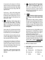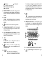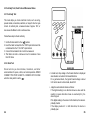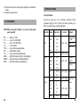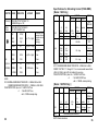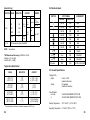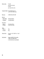
1
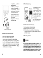
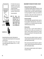
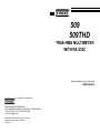
509
509THD
TRUE-RMS MULTIMETER
WITH RS-232C
Please read before using this equipment.
USER’S MANUAL
a world leader in test & measurement
FINE INSTRUMENTS CORPORATION
341-5, SONGNAE-DONG, SOSA-GU, BUCHON-SHI, KYUNGGI, KOREA
-TEL:(82-32) 656-8771~4 -FAX:(82-32) 656-5844
-E-mail:finest @ktnet.co.kr
© Copyright 1999 Fine Instruments Corp. All right reserved.
Specifications subject to change without notice.
Litho in Korea.
Measurement Limits:
DC Voltage
: 0.1 mV to 1000 V
AC Voltage
: 1 mV to 750 V
DC Amps
: 0.1 µA to 10 A
AC Amps
: 0.1 µA to 10 A
Resistance
: 0.1 Ω to 40 MΩ
Capacitance
: 0.001 µF to 999 µF
SOURCES LIKE SMALL HAND-HELD RADIO
Frequency
: 0.5 Hz to 200 kHz
TRANSCEIVERS, FIXED STATION RADIO AND
Temperature
: - 40 °C to + 1,370 °C (- 40 °F to + 2,498 °F)
TELEVISION TRANSMITTERS, VEHICLE RADIO
Continuity Check : Beep at Approx. < 100 Ω in the 4 KΩ range
TRANSMITTERS AND CELLULAR PHONES
THD @ 50/60Hz® : 0.0% to 99.9% [509 THD Only]
WARNING!
GENERATE ELECTROMAGNETIC RADIATION
THAT MAY INDUCE VOLTAGES IN THE TEST
LEADS OF THE MULTIMETER. IN SUCH CASES
THE ACCURACY OF THE MULTIMETER
WARNING!
READ “SAFETY CONSIDERATIONS” BEFORE USING THIS
METER.
CANNOT BE GUARANTEED DUE TO PHYSICAL
REASONS.
CONTENTS
1. Introduction
2. Safety Considerations
3. Explanation of Controls and Indicators
4. Basic Electrical Tests and Measurements
5. RS-232C Interface
6. Maintenance and Battery/Fuse(s) Replacement
7. Accessories
8. Specifications
2
3
5
17
36
46
48
49
1
1. INTRODUCTION
This Meter is a handheld and battery operated instrument that is
designed and tested according to IEC Publication 1010-1 (EN
61010-1) (Overvoltage Category ll), the EMC Directive (EN 500811 and EN 50082-1) and other safety standards (see
“Specifications”).
Features:
■THD @ 50/60Hz ® measurement (Optional)
■33/4 digit, 4000 count with 41 segment bar graph
■Auto/manual ranging
■Safety shutter to prevent incorrect connections to current
terminals
■Fused 10 Amps range
■Back-light
■True RMS on AC voltage and current ranges
■Auto-Power-Off Mode
■DC voltage basic accuracy within 0.3%
■Fix Hold TM (Automatic reading hold)
Fix Hold TM is a trademark of Fine Instruments Corp.
THD @ 50/60Hz ® is a registered trademark of Fine instruments Corp.
■Capacitance measurement
■Frequency measurement
■Temperature measurement
■ Continuity beeper and diode test
■Recording, offset and relative mode
■Comparator, GO-NO GO and percentage programming feature
■600 volt input protection on ohm range
■Hold and Low-battery annunciators
2
■Rubber boot (or Safety holster)
■Large LCD display (68.5 mm x 32.7 mm)
■RS-232C interface
2. SAFETY CONSIDERATIONS
Before using this Meter, read the following safety information
carefully. In this manual, the word “WARNING” is used for
conditions and actions that pose hazard(s) to the user; the word
“CAUTION” is used for conditions and actions that may damage
this Meter.
International Symbols
Dangerous Voltage ( Risk of electric shock)
Not Applicable to Identified Model
Alternating Current (AC)
Direct Current (DC)
Either DC or AC
Diode
Capacitor
Ground (Allowable applied voltage range between the
input terminal and earth)
Caution! Refer to the user’s manual before using this
Meter.
Double Insulation (Protection Class ll)
Fuse
3
WARNING!
3. EXPLANATION OF CONTROLS AND INDICATORS
OBSERVE ALL SAFETY PRECAUTIONS WHEN MEASURING
HIGHER VOLTAGES (AND/OR CURRENTS). TURN OFF
POWER TO THE CIRCUIT UNDER TEST, SET THIS METER TO
THE DESIRED FUNCTION AND RANGE, CONNECT THE TEST
LEADS TO THIS METER AND THEN TO THE CIRCUIT UNDER
TEST. REAPPLY POWER. IF AN ERRONEOUS READING IS
OBSERVED, DISCONNECT POWER IMMEDIATELY AND
RECHECK ALL SETTINGS AND CONNECTIONS.
Safety Tips:
• Do not try to measure any voltage that exceeds 1000V DC or
750V AC RMS.
• Voltages above 60V DC or 25V AC RMS may create a serious
shock hazard.
• Do not attempt to use this Meter if either the Meter or the test
leads have been damaged.
• Turn off power to the circuit under test before cutting,
desoldering, or breaking the circuit. Small amounts of current can
be dangerous.
• Disconnect the live test lead before disconnecting the common
test lead.
• When using the test leads, keep your fingers away from probe
contacts. Always grip behind the finger guards on the probes.
• Use a current clamp if measuring any current above 10 Amps.
4
5
the LO (low) reference value. If the compared reading is
between the HI(high) reference and the LO (low) reference,
a symbol “PASS” will be displayed on the LCD.
DIGITAL DISPLAY. Digital readings are displayed on a 4000
count display with polarity indication and automatic decimal
point placement. When this Meter is turned on, all display
segments and symbols appear briefly during a selftest. The
display updates four times per second.
ANALOG BAR GRAPH. The bar graph provides an analog
representation of readings and updates 20 times per second.
The 41 segment bar graph illuminates from left to right as the
input increases. If the input equals or exceeds 4000 counts on
the range selected, the bar graph displays an arrow at the far
right of the display in case of positive input (an arrow at the far
left in case of negative input).
Press the arrow (↑) button to increase the blinking number
displayed on the LCD by 1 digit when the Meter is in the
Editing mode.
⑥
(Display Back-Light). Press the HOLD button for 2
seconds to turn on the back-light. Back-light turns off
automatically after 60 seconds to extend battery life. To turn
off the back-light even before 60 seconds, press The HOLD
button for 2 seconds again.
Once the HI (high) reference value is entered (stored), press
the HI/LO button to enter the LO (low) reference value into
the meter. When you press the HI/LO button, the arrow at
the left of the bar graph will come on. This indicates that the
value you will put in is the LOW (low) reference value. Using
the arrow (↑, ↓, →, and ←) buttons and the HOLD button
enter the LO (low) reference value that you want your
readings to be compared to.
. Automatically captures a stable reading, beeps to
acknowledge, and holds it on the LCD. But, simply freezes a
reading when the Meter is in the Recording, Compare,
Relative or Percentage mode.
. (Enables GO-NO GO test when the Meter is in the
Compare mode; works as an Increment button when the
Meter is in the Editing mode).
Press the CMP button to compare a reading with the stored HI
(high) reference value and the stored LO (low) reference
value. The “ C ” symbol turns on. A symbol “ – Hi– ” will
be displayed on the LCD if the compared reading is higher
than the HI(high) reference value and a symbol “ - LO - “ will
be displayed on the LCD if the compared reading is lower than
6
(Programming the Reference value). Press the
EDIT button to program a new reference value by using the
arrow ( ↑, ↓, →, and ←) buttons when this Meter is in the
Compare, Relative, or Percentage mode. You don’t need an
external reference source in these modes. When you press
the EDIT button, the “0” at the right side of the LCD will begin
to blink and the arrow at the right of the bar graph will come
on. This indicates that the value you will put in is the HI (high)
reference value. Using the arrow (↑, ↓, →, and ←) buttons
enter the HI(high) reference value that you want your readings
to be compared to. Use the HOLD button to select “
” sign.
Press the EDIT button to exit this mode.
⑦
[ Selects the Manual Range mode in the NonEditing mode; Enables the Meter to store the HI
(high) reference value or the LO (low) reference value in
the Compare mode].
7
HI/LO
Press the RANGE button to select the Manual Range mode
and turn off the “AT” symbol. (The meter remains in the
range it was when manual ranging was selected.)
When this Meter entered the Recordings mode, Auto Power
Off is disabled and this Meter will automatically switch to
Standby Mode after around 1 hour to save battery life unless
you disabled the Standby Mode. To disable the Standby
Mode, turn the rotary switch from OFF to any function (ON)
position while holding down the HOLD button.
Each time you press the RANGE button in the Manual
Range mode, the range increases and a new value is
displayed. If you are already in the highest range, the meter
wraps around to the lowest range. To exit the Manual Range
mode and return to autoranging, press and hold down the
RANGE button for 2 seconds. The “AT” symbol turns back
on. When the range is changed manually, the Recording,
Percentage (%), Compare, Relative and Hold modes are
disabled.
If you press any ineffective button to the Recording mode,
the Meter will sound 2 consecutive beeps to let you know
that the button function does not work in the Recording
mode.
To exit this mode and erase recorded readings, hold the
REC button down for 2 seconds.
Press the HI/LO button to enable the Meter to edit and store
the HI (high) reference value or the LO (low) reference value
by toggling between the 2 reference values when the Meter
is in the Compare mode.
Press the HI/LO (RANGE) button to recall the stored
reference value in the Compare, Relative or Percentage
mode.
⑧
8
. (Maximum, Minimum and Average Recording; A
Left-Shift button when the Meter is in the Editing mode).
Press the REC button to enter the Recording mode. The “ R ”
symbol turns on. This function allows you to record
Maximum, Minimum and Average values for a series of
measurements on the same function and range.
This Meter will beep every time a new maximum or minimum
value is recorded. Press the REC button to scroll through the
stored MAX, MIN and AVG values. When an overload is
captured, a beeper tone emits and the Meter displays
OFL(overload). This Meter can only record for 24 hours in
this mode.
Press the arrow (← ) button to shift the blinking number
position to the left by 1 decimal point when the Meter is in
the Editing mode. When the blinking number is at the very
left, the number will stay at the same position even if you
press the arrow (←) button.
⑨
. (Relative Readings in the Relative mode; A Rightshift button when the Meter is in the Editing mode). In the
Relative mode, this Meter displays the difference between
the stored reference value and the measured reading value.
Press the REL button to enter the Relative mode. The “REL”
symbol will come on the LCD and the bar graph pointer will
be at the center of the scale.
Press the EDIT button to program the reference value. Using
the arrow (↑, ↓, →, and ←) buttons, enter the value you
want the readings displayed in relation to. Once the value is
entered, press the EDIT button to exit the Editing mode. To
recall the stored value, press the HI/LO (RANGE) button.
9
All measurements will be displayed as the difference
between the stored value and the measured value. Negative
readings are lower than the stored value. Positive readings
are higher than the stored value. Pushing the REL button
again exits the mode.
Press the arrow (→ ) button to shift the blinking number
position to the left by 1 decimal point when the Meter is in
the Editing mode. When the blinking number is at the very
right, the number will stay at the same position even if you
press the arrow (→) button.
⑩
⑪
⑫
(Total Harmonic Distortion measurement of
the Line Voltage or Current at 50/60 Hz). [Model: 509THD
Only]
When measuring AC voltage or amperes in the 50Hz (or
60Hz) power line, press and hold down the DC/AC button for
2 seconds to select the THD @ 50/60Hz mode. This mode
enables the user measure THD (Total Harmonic Distortion)
in percentage (%) from the 50Hz (or 60Hz) power line. (See
4.5 THD @ 50/60Hz.)
. (% Readings in the Percentage mode; A
Decrement button when the Meter is in the Editing
mode). In the Percentage mode, this Meter displays the
difference in percentage between the stored reference value
and the measured value.
Press the % button. The “%” symbol will come on the LCD and
the bar graph pointer will be at the zero on the scale. To recall
the stored reference value, press the HI/LO (RANGE) button.
When this Meter enter into the THD @ 50/60Hz mode, the
digital reading (that is, the TRUE-RMS value of voltage and
amperes being measured) disappears and the symbol, %,
and decimal points are displayed on the LCD.
After about 2 seconds from this moment, the THD value in
percentage (%) will be displayed. To exit the THD @ 50/60Hz
mode, press and hold down the DC/AC button for 2 seconds
again. The symbol, “%”, disappears. This feature is typically
found in much more expensive power analyzing meters.
Press the EDIT button. Using the arrow buttons, enter the value
you want the readings displayed as a percentage of. Once the
value is entered, press the EDIT button to exit the mode.
All measurements will be displayed as the difference in
percentage between the stored reference value and the
measured value. Negative readings are lower than the
stored value. Positive readings are higher than the stored
value. Pushing the % button again exits the mode.
Press the arrow (↓) button to decrease the blinking number
displayed on the LCD by 1 digit when the Meter is in the
Editing mode.
10
(Toggles between DC and AC; Toggles between
°C and °F in the Temperature mode). Press the
DC/AC button to toggle between DC and AC when
measuring volts (except mV) or amperes. When the
displayed and when the Fahrenheit scale is selected, the
“°F” symbol is displayed on the LCD.
⑬
OFF. Power to the Meter is turned off.
⑭
ROTARY SWITCH. Describes functions that are selected by
setting the rotary switch.
µA
Microamperes dc/ac
mA
Milliamperes dc/ac
10A
Amperes dc/ac
mV
Millivolts dc only
V
Volts dc/ac
Ω
Resistance
11
Diode test
Continuity test
Hz
Frequency (Autoranging only)
CAP Capacitance (Autoranging only)
TEMP Temperature
⑮
SAFETY SHUTTER. Prevents user from making inadvertent
connections to the current terminals. Caution: ALWAYS
REMOVE INPUTS BEFORE TURNING THE ROTARY
SWITCH.
10A MAX
FUSED . The maximum current that you can measure at
this terminal is 10Amps DC/AC. This terminal is fuse
protected.
. Refer to the user’s manual before using this Meter.
A (Ampered Input Terminal). The red test lead is plugged
into this terminal for measuring current on the 4A or 10A AC
or DC ampere functions.
The red test lead is plugged into this terminal for all AC V,
DC V, Ohms, continuity test, diode test, frequency and
capacitance functions. When measuring temperature, a
thermocouple adapter is plugged into both this terminal and
the COM input terminal.
MAX
600V
. To avoid electrical shock or instrument damage, do
not connect the COM input terminal to any source of more
than 600V with respect to earth/ground.
COM (Common Terminal). The black test lead is plugged
into this terminal for all measurements. When measuring
temperature, a thermocouple adapter is plugged into this
terminal.
mA µA (Milliamp/Microamp Input Terminal). The red test
lead is plugged into this terminal for measuring mA or µA on
either AC or DC ampere functions.
MAX
AC 750V
DC 1000V . The maximum voltage that this Meter can
measure is 1000V DC or 750V AC RMS.
. Be extremely careful when making high-voltage
measurements; DO NOT TOUCH TERMINALS OR TEST
LEAD PROBE ENDS.
VΩHz CAP
TEMP (Volts, Ohms, Diode Test, Frequency,
Capacitance and Temperature Input Terminal).
12
AC . Displayed when AC measurement function is selected.
(Negative Polarity). Automatically indicate negative
inputs.
13
AT. Displayed when the Auto Range mode is selected.
38
C (Compare mode). Displayed when the Compare mode is
selected. This mode allows you to do the GO-NO GO test
(see ⑤).
39
°C (Centigrade degree). The value displayed is the
temperature in Centigrade scale.
40
°F (Fahrenheit degree). The value displayed is the
temperature in Fahrenheit scale.
41
The following symbols indicate the unit of the value
displayed.
O . F . L (Overload Indication). Displayed on the LCD when
input value is too large to display.
(Low Battery). Battery life warning. When
is first
turned on, at least 8 hours of battery life remain. Replace the
battery immediately. Never leave a weak or dead battery in the
Meter. Even leak-proof types can leak and damage the Meter.
. Displayed when the Meter is in the continuity test
function.
31
R . Displayed when the REC button has been pressed.
32
MAX (Maximum Value in the Recording mode). The value
displayed is the maximum reading taken since the Recording
mode was entered.
33
MIN (Minimum Value in the Recording mode). The value
displayed is the minimum reading taken since the Recording
mode was entered.
34
AVG (Average Value in the Recording mode). The value
displayed is the true average of all readings taken since the
Recording mode was entered.
35
REL (Relative mode). The value displayed is the difference
between the present measurement and the previously stored
reading.
36
(Diode test). The value displayed is the forward voltage
of semiconductor junction(s).
37
HOLD. Displayed when the Hold mode is selected.
14
µF
%
V
mV
A
mA
µA
Ω
KΩ
MΩ
Hz
KHz
Microfarads (1 x 10 – 6 Farads)
Percentage Annunciator in the both Percentage (%)
mode and THD @ 50/60Hz mode. [The THD @
50/60Hz mode is available for Model: 509THD
Only]
Volts
Millivolts (1 x 10 – 3 Volts)
Amperes (Amps)
Milliamperes (1 x 10 – 3 Amps)
Microamperes (1 x 10 – 6 Amps)
Ohms
Kilohm (1 x 10 3 Ohms)
Megohm (1 x 10 6 Ohms)
Hertz (1 cycle/sec)
Kilohertz (1 x 10 3 cycles/sec)
15
Using Holster and Stand
BOTTOM CASE
42
42
RS-232C TERMINAL. The standard D9 male connector of the
RS-232C serial cable (RS50) is plugged into this terminal
when interfacing to a PC. The RS-232C serial cable is
optional.
Auto-Power-Off Mode
If this Meter is on and inactive for approximately 30 minutes (1
hour in the Recording mode), this Meter will automatically switch to
Auto-Power-off Mode. To resume operation, turn the rotary switch
back to the OFF position and then turn Meter on again. To disable
the Auto-Power-Off Mode, turn the rotary switch from OFF to any
function (ON) position while holding down the HOLD button.
Using Test Leads
Use only the same type of test leads as are supplied with the
Meter. These test leads are rated for 1200 volts. Although these
test leads are rated for 1200 volts, do not try to measure any
voltage greater than 1000 volts DC or 750 volts AC.
NOTE: In some DC and AC voltage ranges with the test leads
not connected to any circuit, the display may show
fluctuating readings due to the high input impedance.
This is normal. When you connect the test leads to a
circuit, a real measurement appears.
16
The Meter comes with a protective holster that absorbs shocks
and protects the Meter from rough handling. The holster is
equipped with a stand rest.
4. BASIC ELECTRICAL TESTS AND MEASUREMENTS
4.1 Measuring Voltage
WARNINGS!
TO AVOID THE RISK OF ELECTRICAL SHOCK AND
INSTRUMENT DAMAGE, INPUT VOLTAGES MUST NOT
EXCEED 1000V DC OR 750V AC (RMS). DO NOT ATTEMPT TO
TAKE ANY UNKNOWN VOLTAGE MEASUREMENT THAT MAY
BE IN EXCESS OF 1000V DC OR 750V AC (RMS).
THIS METER IS DESIGNED FOR MEASUREMENT IN WEAK
CURRENT CIRCUITS. DO NOT USE IT FOR STRONG
CURRENT CIRCUITS (POWER LINE IN FACTORIES AND SO
ON HAVING LARGE CURRENT CAPACITY). USE IN STRONG
CURRENT CIRCUITS IS VERY DANGEROUS BECAUSE
SURGE VOLTAGE IN FAR EXCESS OF RATING IS OFTEN
APPLIED TO THEM.
NOTE: When taking voltage measurements, this Meter must
be connected in PARALLEL with the circuit, or circuit
element under test.
17
• To improve the accuracy of DC voltage measurements taken in
the presence of AC voltages (such as, measuring the DC
voltage of an amplifier in the presence of an AC signal),
measure the AC voltage first. Note the just measured AC
voltage range and select a DC voltage range that is the same or
higher than the AC voltage range. This method improves the
DC voltage accuracy by preventing the input protection circuits
from being activated.
4.1.1 Measuring DC Volts
Follow these steps to measure DC volts.
• In 400mV range, displayed value may fluctuate when
disconnecting input terminals. This is normal.
• AC voltage measuring circuit in this Meter is of rootmeansquare (True-RMS) value system so this Meter can
accurately measure AC voltage of non-sinusoidal wave forms
including harmonics caused by various non-linear loads.
For an AC voltages (or current) Meter, CREST FACTOR
expresses its ability to respond to non-sinusoidal waveforms.
[CREST FACTOR is defined as the ratio of the peak voltage of
an AC waveform to its RMS value.] The AC crest factor of this
Meter is 3 for the frequency range of 45Hz to 1KHz.
18
1. Set function and range switch to the desired DC V range. If you
do not know the value of the voltage to be measured, always
start with the highest range and reduce the setting as required
to obtain a satisfactory reading.
2. Plug the red test lead into the “VΩHz CAP” input terminal and
the black lead into the “COM” input terminal of the instrument.
3. Disconnect the power from the circuit to be tested.
4. Connect the test leads to the circuit to be tested.
5. Reapply power to the circuit, the measured voltage will appear
on the display of the instrument.
6. If the red test lead is connected to the negative (or lower
voltage) side of the circuit, a minus sign will appear on the
display, at the left.
7. Disconnect power to the circuit before removing the test leads
from the circuit.
19
4.1.2 Measuring AC Volts
4.2 Measuring Resistance (Ohms)
Follow these steps to measure AC volts.
CAUTION!
1. Set function and range switch to the desired AC V range.
If you do not know the value of the voltage to be measured,
always start with the highest range and reduce the setting as
required to obtain a satisfactory reading.
2. Plug the red test lead into the “VΩHz Cap” input terminal and
the black lead into the “COM” input terminal of the instrument..
3. Disconnect the power from the circuit to be tested.
4. Connect the test leads to the circuit to be tested.
5. Reapply power to the circuit, the measured voltage will appear
on the display of the instrument.
6. Disconnect power to the circuit before removing the test leads
from the circuit.
Three-Phase AC Volts
This Meter is designed to primarily measure household AC
voltage. When measuring THREE-PHASE circuits line-to-line, the
value of the voltage is actually higher than the rated line-to-ground
3-phase voltage. It is very important that you do not exceed the
maximum AC (RMS) rating of this Meter, 750V AC. To find the
RMS voltage line-to-line on a 3-phase power line, multiply the
rated line-to-ground voltage by the square root of 3 (approx.
1.732).
TURN OFF POWER AND DISCHARGE ALL CAPACITORS ON
CIRCUIT TO BE TESTED BEFORE ATTEMPTING INCIRCUIT
RESISTANCE MEASUREMENTS. FAILURE TO DO SO MAY
END UP IN EQUIPMENT (AND/OR INSTRUMENT) DAMAGE.
THE RESISTANCE MEASURING CIRCUIT APPLIES A KNOWN
VALUE OF CONSTANT CURRENT THROUGH THE UNKNOWN
RESISTANCE AND THEN MEASURES THE VOLTAGE
DEVELOPED ACROSS IT. THEREFORE, REMOVE ALL
POWER TO THE CIRCUIT UNDER TEST WHEN MAKING
RESISTANCE MEASUREMENTS. IF ANY VOLTAGE IS
PRESENT IN THE TEST CIRCUIT, AN ERRONEOUS READING
WILL RESULT. THIS METER MAY BE DAMAGED IF VOLTAGE
IN EXCESS OF 600V AC IS PRESENT.
NOTE: When measuring critically low ohm values, touch tips
of test leads together and record the reading. Subtract
this reading from any additional measurement to
obtain the most accurate value.
For example, if you connect this Meter to a 480 volts 3-phase
line(i.e. 480V line-to-ground), the total available voltage line-to-line
is about 832V AC (≒480V x 1.732). Severe damage and a
dangerous shock hazard could result because this exceeds the
rating of this Meter.
20
21
• The current applied during resistance measurements could
damage some devices. The table below lists the test voltage
and current available for each resistance measurement range.
(All values are typical.)
RANGE
400 Ω
4 KΩ
40 KΩ
400 KΩ
4 MΩ
40 MΩ
OPEN CIRCUIT
VOLTAGE (A)
< 1.2 V
FULL SCALE SHORT CIRCUIT
VOLTAGE (B) CURRENT (C)
< 200 mV
< 320 mV
< 340 mV
< 340 mV
< 340 mV
< 1mV
< 740 µA
< 60 µA
< 11 µA
< 1.5 µA
< 0.2 µA
< 0.2 µA
NOTE: (A) is the open circuit test voltage at the input
terminals in volts.
(B) is the voltage drop across a resistance equal to full
scale value.
(C) is the current through a short circuit at the input
terminal.
• When measuring large resistance, reading may be unstable due
to environmentally induced electrical noise. In this case, directly
connect the resistor to input terminals of the Meter or shield the
resistor at potential of the COM input terminal to obtain stable
reading.
• For resistance above 1 Megohm, the display may take a few
seconds to stabilize. This is normal for high-resistance readings.
• The Meter has a circuit to protect the resistance range from
over-voltage (600V AC). However, to prevent accidentally
exceeding the protection circuit’s rating and to ensure a correct
measurement, NEVER CONNECT THE TEST LEADS TO A
SOURCE OF VOLTAGE when the rotary switch is set to Ω or
or
functions.
22
4.2.1 Measuring Resistance (Ohms)
When measuring resistance, be sure that the contact between the
test leads and the circuit under test is good. Dirt, oil, solder flux, or
other foreign matter seriously affect the reading value.
Follow these steps to measure ohms.
1. Set the Function switch to the desired “Ω” position.
2. Insert the black test lead into the “COM” input terminal and the
red test lead into the “VΩHz CAP” input terminal.
3. Connect the test leads to the circuit to be measured.
4. The measured resistance will be displayed on the LCD.
23
4.3 Continuity Test, Diode Test and Microwave Diodes
4.3.1 Continuity Test
This mode helps you check electrical circuits, such as wiring,
speaker cables, connections, switchers, or relays for short or open
circuits. In continuity test, a measured value of approx. 100Ω or
less causes the Meter to emit a continuous tone.
Follow these steps to check continuity.
1. Set the Function switch to the “
” position.
2. Insert the black test lead into the “COM” input terminal and the
red test lead into the “VΩHz CAP” input terminal.
3. Connect the test leads to the circuit to be measured.
4. This Meter will emit a continuous tone for resistance of less
than 100 ohms.
4.3.2. Diode Test
Diode test lets you check diodes, transistors, and other
semiconductors for opens, shorts, and normal operation. NEVER
CONNECT THE TEST LEADS TO A SOURCE OF VOLTAGE
when the rotary switch is set to
.
24
• In diode test, drop voltage in the forward direction is displayed
when diode is connected in the forward direction.
For a germanium diode, the typical forward voltage is about
0.4V and in case of a silicon diode, about 0.6V.
• Judge the semiconductor device as follows:
If the digital reading in one direction shows a value and the
reading in reverse direction shows an overload (O . F . L), the
device is good.
If the digital reading is the same in both directions, the device is
probably shorted.
If the display reads O . F . L in both directions, the device is
probably open.
25
Follow these steps to check a diode.
1. Set the Function switch to the “
” position.
2. Insert the black test lead into the “COM” input terminal and the
red test lead into the “VΩHz CAP” input terminal.
3. Touch the red test lead to the Anode ( + side, non-banded end )
and the black test lead to the Cathode ( – side, banded end ).
4. If the diode is good, the reading should indicate 0.3V to 0.8V on
the LCD.
5. Reverse the red and black leads on the diode, if the LCD reads
O.F.L (the overload sign), the diode is good.
NOTE: When taking current measurements, this Meter must
be connected in SERIES with the circuit (or circuit
element) under test. NEVER CONNECT THE TEST
LEADS ACROSS A VOLTAGE SOURCE while the
rotary switch is set to Amps. This can cause damage
to the circuit under test or this Meter.
NOTE: A defective diode will read O.F.L (the overload sign) or
0.00 no matter how the test leads are connected.
4.3.3. Microwave Diodes
Most microwave diodes can not be tested by a DMM with a diode
test function. This is because the DMM does not supply enough
power to turn these diodes on. We offer an accessory test lead,
model TL60, that boosts the power output so that microwave
diodes can be adequately tested. Consult your distributor for more
details.
4.4. Measuring Current (Amps)
CAUTION!
THE CURRENT FUNCTIONS ARE PROTECTED BY A FUSE OF
600 VOLT RATING. TO AVOID DAMAGE TO THE
INSTRUMENT, CURRENT SOURCES HAVING OPEN CIRCUIT
VOLTAGES GREATER THAN 600 VOLTS DC OR AC MUST
NOT BE MEASURED.
26
• To measure current, you must break the circuit and connect the
test leads to two circuit connection points. The connection must
be in series with the current.
27
• AC current measuring circuit in this Meter is of root-meansquare
(True-RMS) value system so this Meter can accurately measure
AC current of non-sinusoidal wave forms including harmonics
caused by various non-linear loads. The AC crest factor of this
Meter is 3 for the frequency range of 45Hz to 1KHz.
These solid state switches create non-linear loads on the power
distribution systems, which generate harmonics. These harmonics
are odd multiples of the fundamental power line frequency, and
may cause overheating in transformers, erratic computer operation
and premature tripping of circuit breakers.
• When measuring current, the Meter’s internal shunt resistors
develop a voltage across the Meter’s terminals called “burden
voltage”. This voltage drop affect prec ision circuits or
measurements.
One of the most useful measurements of harmonics is Total
Harmonic Distortion THD. This measurement requires special and
expensive instrumentation to indicate the sum of all the harmonic
frequencies present in the signal.
Follow these steps to measure DC (or AC) Amps.
This Meter is designed to indicate the total rms values of the 3rd
harmonic to the infinite order harmonic as a percentage of the total
rms value including the rms value of the fundamental frequency in
the 50Hz/60Hz power lines.
1. Set function and range switch to the desired DC A (or AC A)
range. If you do not know the value of the current to be
measured, always start with the highest range and reduce the
setting as required to obtain a satisfactory reading.
2. Plug the red test lead into the “mAµA” input terminal (if the 4A
or 10A ranges are being used, plug the red test lead into the “A”
input terminal) and the black test lead into the “COM” input
terminal of the instrument.
3. Disconnect the power from the circuit to be tested.
4. Connect the test leads in series to the circuit to be tested.
5. Reapply power to the circuit, the measured current will appear
on the display of the instrument.
6. Disconnect power to the circuit before removing the test leads
from the circuit.
4.5 THD @ 50/60 Hz ® Mode [509THD Only]
Today, more and more electrical appliances are using high
efficiency power supplies and adjustable speed motors to conserve
energy. These appliances conserve power by drawing current in
short pulses using a solid state switch, This trend, although saving
energy, creates severe problems in power distribution.
28
In general, there are two ways to express the THD value:
THD-F = Total Harmonic Distortion as a percent of the
fundamental frequency.
THD-R = Total Harmonic Distortion as a percent of the total rms
value.
Practically speaking, either method is useful when looking at
harmonics of a high enough value to create problems. When
measuring line voltage, a maximum THD level of 5% or less is
considered acceptable. Below the 5% level, both measurements
(THD-R and THD-F) are essentially the same. For THD levels
above 5%, you can convert THD-R readings to THD-F readings
using either the following formula or conversion chart.
F (%)=
100 X R (%)
10000-R2 (%)
Where F (%)=THD-F (%)and
R (%)=THD-R (%)
29
As you can see from this
table, both THD-R (%)
and THD-F (%) values
are essentially the same
when measuring line
voltage where THD
readings are often 5% or
less. The values differ
only when THD levels
exist above about 20%.
The maximum THD
levels on line voltage of
around 5% and the
maximum THD levels on
line current of around
20% are common for a
power line.
THD-R (%) versus THD-F (%)
Follow these steps to measure THD-R (%) in the power line.
THD-R (%)
0.00
5.00
10.00
15.00
20.00
25.00
30.00
35.00
40.00
50.00
55.00
60.00
65.00
70.00
75.00
80.00
85.00
90.00
95.00
95.00
100.00
1. Set function and range switch to the AC Volts or Amps range.
2. When measuring voltage or amperes in the 50Hz (or 60Hz)
power line, press and hold down the DC/AC button for 2
seconds to select the THD @ 50/60Hz mode.
3. When this Meter enters into the THD mode, the digital reading
(that is, the True-RMS value of voltage or amperes being
measured) disappears and the symbol, %, and decimal points
are displayed on the LCD.
4. After about 2 seconds from this moment, the THD-R (%) will be
displayed.
5. To exit this mode, press and hold down the DC/AC button for 2
seconds again. The symbol, %, disappears and the Meter will
return to the AC functions.
THD-F (%)
0.00
5.01
10.05
15.17
20.41
25.82
31.45
37.36
43.64
50.39
57.74
65.86
75.00
85.53
98.02
113.39
133.33
161.36
206.47
304.24
∞
CREST FACTOR versus THD-R (%) [or THD -F (%)]
4.6 Measuring Capacitance
CAUTION!
DISCHARGE ALL CAPACITORS BEFORE ATTEMPTING TO
MAKE MEASUREMENTS. FAILURE TO DO SO CAN RESULT
IN DAMAGE TO THE METER.
A CREST FACTOR simply indicates whether harmonic contents
are included or not in the power line. However, THD-R (%) [or
THD-F (%)] at 50Hz (or 60Hz) indicates what percent of harmonic
contents is included in the power line. Both features are typically
found in much more expensive professional power analyzing
instruments.
30
31
• In capacitance, the Meter is
always autoranging.
• In 1µF range, the readings are
probably unstable due to
environmentally induced
electrical noise and floating
capacity of the test leads.
Therefore, directly connect the
object to be measured to the
input terminals.
• Bar graph does not function in
capacitance mode.
4.7 Measuring Frequency
• In frequency, the Meter is
always autoranging.
• When disconnecting the
input terminals, the
overload sign may be
displayed or the display
may unsteadily fluctuate.
This is typical.
• Bar graph functions in
frequency measurement.
Follow these steps to measure frequency.
PARALLEL CONNECTION
Follow these steps to measure capacitance.
1. Insert the test leads into the input terminals.
2. Set the rotary switch to the “CAP” position.
3. Touch the probes to the capacitor and read the display.
When measuring polarized capacitors, connect the positive to
the VΩHz CAP terminal and the negative to the COM terminal.
Capacitor dielectric absorption can cause measurement errors.
If more discharge is necessary, the Meter displays “
”
while the capacitor is discharging.
32
1. Insert the test leads in the input terminals.
2. Set the rotary switch to the “Hz” position.
3. Touch the probes to the test points, and read the display.
If the measured frequency is greater than 200 KHz, “O . F . L”
(overload) is displayed.
4.8 Measuring Temperature
WARNING!
DO NOT ALLOW TEMPERATURE PROBES TO CONTACT ANY
LIVE VOLTAGE THAT MAY EXCEED 30 AC V RMS OR 42 AC V
PEAK OR 60 DC V. UNPLUG TEMPERATURE PROBE BEFORE
TAKING MEASUREMENTS OTHER THAN TEMPERATURE.
INSTRUMENT AND/OR EQUIPMENT DAMAGE COULD
RESULT IF THE ABOVE WARNINGS ARE NOT FOLLOWED.
33
• This Meter directly measures
temperature using a K-type
thermocouple which optionally
supplied with this Meter.
• This Meter displays temperature
measured in degrees either
Celsius or Fahrenheit.
NOTE: This
Meter
automatically defaults to the
Centigrade scale. To
measure in Fahrenheit,
toggle the DC/AC button
when the rotary switch
is set to TEMP position.
MEASUREMENT TECHNIQUES FOR THE BEST ACCURACY
• Choosing a Proper Thermocouple Probe
The thermocouple optionally supplied with this Meter is a bead
type thermocouple, which is designed for general-purpose use.
For optimum accuracy, use the style of probe that is appropriate
for each type of application. For example, use an air probe for air
measurements, a surface probe for surface measurements, and
an immersion probe for liquid or gel measurements.
• Thermocouple Adapter
The thermocouple adapter supplied with this Meter is made from
the same materials as thermocouple wires. To avoid error, it is
very important to use a thermocouple adapter whose materials
match the thermocouple you are using.
• To Reduce Errors
Ensure that there is a good connection between the
thermocouple and the surface you are measuring. For this
purpose, a thermal conducting compound (such as silicone
grease) can be used between the thermocouple and the surface
you are measuring.
• Repeated sharp flexing can break the thermocouple lead.
To prolong lead life, avoid sharp bends in the lead, especially
near the connector.
• The temperature meas urement range of the K-type
thermocouple supplied with this Meter is -40°C to + 1,370°C (40°F to + 2,498°F).
When measuring above-ambient temperatures, adjust the
connection between the thermocouple and the surface until you
get the highest temperature reading.
When measuring below-ambient temperatures, adjust the
connection between the thermocouple and the surface until you
get the lowest temperature reading.
When measuring near-ambient temperatures, take the reading when
the display is most stable.
34
35
Follow these steps to measure temperature.
1. Set the rotary switch to the “TEMP” position.
2. Plug the thermocouple adapter into the COM input terminal and
the TEMP input terminal observing the proper polarity.
3. Plug a K-type thermoc ouple probe connector into the
thermocouple adapter observing the proper polarity.
4. Read the temperature on the LCD.
5. RS-232C INTERFACE
5.1 Introduction
The RS- 232C connector’s pin configuration is as follows
< DMM >
< Computer >
2
3
4
5
7
3 RXD
2 TXD
20 DTR
7GND
4 RTS
13
MICOM SIDE COMPUTER SIDE
25
DTR
5
TXD
9
DTR
GND
RS-232C is an EIA-defined standard for a serial communications
interface commonly used between computers, terminals, and
modems.
This Meter is capable of RS-232C interface with a DOS computer
by using its bi-directional RS-232C serial interface cable and its
DOS software supplied as optional accessories along with this
Meter.
5.2 Interfacing the Meter with a Personal Computer
RXD
RTS
RXD
RTS
1
6
TXD
GND
9PIN
RXD
1
TXD
14
25PIN
2. Turn on the Meter and Press the RS-232C (REL) button for 2
seconds to activate the RS-232C communication. The symbol
‘RS-232C’ will appear on the LCD.
Follow these steps to interface the Meter with a DOS computer.
1. Connect the RS-232C cable to the computer’s 25-pin serial
port. Plug the D9 male connector into the RS-232C terminal on
the back of the Meter.
The RS-232C driver is powered by ± 12V supplied from the
interfaced computer through “DTR” and “RTS” pins of the D25
female connector.
36
3. Load the DOS software diskette, which is optionally supplied for
the Meter, on the computer. This software requires a VGA or
upper-class monitor.
4. Copy the files from the software diskette to the computer’s hard
disc to make a back-up copy.
5. Run the execution file loaded from the DOS software diskette
by typing the name of the execution file at the DOS prompt.
37
6. Press the enter key and you will see the first screen showing
our company’s name.
Press the enter key again you will see the second screen
showing features of this Meter.
Press the enter key again and you will see the measurement
screen with the menu.
7. Now you can have access to various functions of the Meter
using the menu and your computer can log various necessary
data and control various to buttons of the Meter.
NOTE: For the operation method in details, refer to the
“README.TXT” file in the DOS software diskette.
Don’t Forget!
• MOUSE usage:
LEFT KEY – SHORT KEY
(= short press on the DMM button)
RIGHT KEY – LONG KEY
(= long press on the DMM button)
MOUSE
LEFT KEY
RIGHT KEY
HOLD
(BACK LIGHT)
SET/EXIT
HOLD
SET/EXIT
BACK LIGHT
REC
(←)
SET & SCROLL THRU
MAX, MIN, AVG
(←) in the EDIT model)
EXIT
REL
(→)
SET/EXIT
MAX, MIN, AVG
(→) in the EDIT model)
SET/EXIT
RS-232C Interface
RANGE
(HI/LO)
SET MANUAL RANGE
(TOGGLE HI/LO in the
EDIT/COMPARE mode)
SET AUTO RANGE
COMPARE
(↑)
SET/EXIT
(↑ in the EDIT mode)
–
%
(↓)
SET/EXIT
(↓ in the EDIT mode)
–
EDIT
SET/EXIT
–
DC/AC
(°C/°F)
TOGGLE DC/AC
(TOGGLE °C/°F)
SET/EXIT
THD@50/60 Hz
BUTTON
ONE BEEP sounds when an available function is selected.
TWO BEEPS sound when a unavailable function is selected.
38
39
• FILE MENU usage:
MEASUREMENT. Displays STOP MEASUREMENT on the pull
down menu; pressing <ESC> enables the Meter to start to
measure, when the pull down menu disappears.
• FILE SPECIFICATION
EXTENTION
MINUTE
µA
HOUR
STOP MEASUREMENT. Enables the Meter to stop
measurements and the initial picture appears again, when the
pull down menu will be disappeared by pressing <ESC>. DATA
VIEW. Shows the measured date; EMPTY DATA! is displayed if
there are no data.
: MICRO AMPERES MODE
MA : MILLI AMPERES MODE
DATE
A
MONTH
: 10 AMPERES MODE
MV : MILLI VOLTS MODE
V
: VOLTS MODE
OHM : OHM MODE
BEP : BEEP MODE
DIO : DIODE MODE
DATA PRINT. Prints the data displayed in DATA VIEW; EMPTY
DATA! is displayed if there are no data; PRINTER IS NOT
READY! is displayed when the computer is not connected to a
printer. Then, immediately press <ESC> to exit DATA PRINT.
Otherwise, the picture on the screen may be damaged.
GRAPH DISPLAY. Select Graph Scale to draw the graph with
the data and the press <ESC> to autosave the graph on
SCREEN . PCX; If GRAPH DISPLAY will be selected after
having entered in the other measurement mode, the previous
SCREEN .PCX will be overwritten; EMPTY DATA! is displayed if
there are no data.
CONFIGURATION.
COMMUNICATION PORT : Select 1 or 2
PRINT PORT
: Select 1 or 2
SAMPLING TIME
: Select any rate more
than 1 sec.
EXIT
: SAVE→ < ENTER>
→EXIT of the FILE MENU
enables the program to rerun.
40
TEC : °C MODE
TEF : °F MODE
CAP : CAPACITANCE MODE
FRE : FREQUENCY MODE
FILE NAME
5.3 Designing Your Own Software
You need the following information if you are designing your own
software for the RS-232C interface.
5.3.1 Communication Parameters
•
•
•
•
Transmission rate
Data Bit
Stop Bit
Parity
:
:
:
:
4800 Baud
8
1
None
41
5.3.2 Transmit Data Format
STX
•
•
•
•
•
•
•
ID
POSITION
5.3.3 Receive Data Format
RANGE
STATUS
DATA
ETX
STX (1 BYTE): F2H
ID (1 BYTE): 09H
POSITION (1 BYTE)
RANGE (1 BYTE)
STATUS (7 BYTE)
DATA (6 BYTE)
ETX (1 BYTE): F3H
STX
•
•
•
•
ID
DATA
ETX
STX (1 BYTE): F2H
ID (1 BYTE): 09H
DATA (1 BYTE)
ETX (1 BYTE): F3H
Example : DATA FORMAT
MSB
LSB
Example : POSITION DATA FORMAT
0
MSB
0
0
0
LOW BATT BIT 3 BIT 2
BIT 1
BIT 0
• LOW BATT = 0: INACTIVE
= 1: LOW BATTERY
• BIT 3
0
0
0
0
0
0
0
0
1
1
1
42
0
0
LONG KEY BIT 3 BIT 2 BIT 1
BIT 0
LSB
BIT 2
0
0
0
0
1
1
1
1
0
0
0
BIT 1
0
0
1
1
0
0
1
1
0
0
1
BIT 0
0
1
0
1
0
1
0
1
0
1
0
=
=
=
=
=
=
=
=
=
=
=
DC mV
AC/DC V
AC/DC µA
AC/DC mA
AC/DC A
Ohm (Ω)
BEEP
DIODE
TEMPERATURE (°C/°F)
CAPACITANCE (µF)
FREQUENCY (Hz)
• BIT 4 = 0: LONG KEY INACTIVE
= 1: LONG KEY ACTIVE
• BIT 3
0
0
0
0
0
0
0
0
1
BIT 2
0
0
0
0
1
1
1
1
0
BIT 1
0
0
1
1
0
0
1
1
0
BIT 0
0
1
0
1
0
1
0
1
0
=
=
=
=
=
=
=
=
=
NO KEY
RANGE KEY
HOLD KEY
AC/DC KEY
RECORD KEY
RELATIVE KEY
PERCENTAGE KEY
COMPARE KEY
EDIT KEY
43
5.3.4 A Sample Program (FICOM.H)
/* Parameters to bioscom function */
The following program is an example of a C language program
which helps users to understand the data format and the data
interfacing method, and also to develop their own programs.
#define DATABIT7 0X02 /* Data bit */
#define DATABIT8 0X03
#define STOPBIT1 0X00 /* Stop bit */
#define STOPBIT2 0X04
[Interrupt Usage and Selection between COM1 and COM2]
#define NOPARITY 0X00 /* Parity bit */
#define ODDPARITY
0X08
#define EVENPARITY
0X18
#define COM1 0
#define COM2 0
/* Base addresses of serial ports */
#define COM1BASE 0x03f8
#define COM2BASE 0xx02f8
#define COMBASE ( (comport = = COM1)?COM1BASE:
COM2BASE)
/* Registers */
#defineTHR (COMBASE +0) /*
#defineRBR (COMBASE +0) /*
#defineIER (COMBASE +1) /*
#defineIIR (COMBASE +2) /*
#defineLCR (COMBASE +3) /*
#defineMCR (COMBASE +4) /*
#defineLSR (COMBASE +5) /*
#defineMSR (COMBASE +6) /*
Transmit Holding Register
*/
Receive Buffer Register
*/
Interrupt Enable Register
*/
Interrupt Identification Register*/
Line Control Register
*/
Modem Control Register
*/
Line Status Register
*/
Modem Status Register
*/
#define BAUD1200
#define BAUD2400
#define BAUD4800
#define BAUD9600
0X80 /* Baud rate */
0Xa0
0Xc0
0Xe0
/* 8259 PIC (Programmable Interrupt Controller */
#defineIMR 0x21 /* I/O address of 0CW1 (IMR) of 8529 PIC
#define0CW 0x20 /* I/O address of 0CW2 of 8259 PIC
/* 0CW: Operation Command Word
/* IMR: Interrupt Mask Register
*/
*/
*/
*/
# define MASKON 0x e7 /* Mask IRQ3/IRQ4 on → IMR */
* define MASKOFF 0x18 /* Mask IRQ3/IRQ4 off → IMR */
#define EOI 0x20 /* Non-specific End of Interrupt command →
0CW2*/
/* Interrupt Request Numbers */
#define IRQ0 0x 08 /* Interrupt Vector for Timer */
#define IRQ3 0x 0b /* Interrupt Vector for COM2 */
#define IRQ4 0x 0c /* Interrupt Vector for COM1 */
#define IRQ8 0x 70 /* Interrupt Vector for RTC (Real TIme Clock) */
#define IRQ16 0x 1C /* Interrupt Vector to called Timer */
#define IRQNUM ( ( comport = = COM1)? IRQ4 : IRQ3)
44
45
*/ Miscellaneous */
6.2 Battery Replacement
#define BUFSIZE 0x4000 /* SIze of comm buffer */
#define BUFFEREMPTY (–1)
/* Buffer empty */
#define ON 1
#define OFF 0
The Meter uses a 9V battery (NEDA 1604 or IEC 6F22). To
replace the battery, remove the two screws of the battery com
parament from the back of the Meter and lift off the cover of the
c ompartment. Replac e the battery. Reattach the battery
compartment to the back of the Meter, and reinstall the screws.
6.3 Fuse(s) Test
6. MAINTENANCE AND REPLACEABLE PARTS
6.1 General Maintenance
WARNING!
REPAIRS OR SERVICING NOT COVERED IN THIS MANUAL
SHOULD ONLY BE PERFORMED BY QUALIFIED
PERSONNEL. TO AVOID ELECTRICAL SHOCK, DO NOT
SERVICE UNLESS YOU ARE QUALIFIED TO DO SO.
Periodically wipe the case with a damp cloth and detergent; do not
use abrasives or solvents. Water, dirt, or contamination in the A or
mAµA input terminals may harm this Meter.
Calibrate this Meter once a year to maintain its performance
specifications.
To test the internal fuses of this Meter:
1. Set the rotary switch to the “
” position.
2. Turn Meter on.
3. To test F2 (15A, 600V), insert a test lead into the VΩHz CAP
input terminal and touch the probe to the A input terminal. The
display should read about 0.000V. If the display reads OFL
(overload), replace the fuse and test again. If the display reads
any other value, have this Meter serviced.
4. To test F11 (1A, 600V), move the probe from the A input
terminal to the mAµA input terminal.
The display should read about 1.2V. If the display reads OFL
(overload), replace the fuse and test again. If the display reads
any other value, have this Meter serviced.
6.4 Fuse(s) Replacement
Follow these steps to replace the internal fuse(s).
1. Unplug the test leads. Remove the rubber boot from the
instrument.
2. Remove the screws in the rear of the instrument and separate
the front and rear housing.
3. Replace the fuse(s) with the same type and size as the one
removed.
46
47
4. Snap the front and rear housing back together and reinstall the
screws.
5. Reattach the rubber boot.
8. SPECIFICATIONS
8.1 Specifications
7. ACCESSORIES
NOTE: When servicing the Meter, use only th replaceable
parts specified.
BT1 .............Battery, 9 Volts
F11 ............. Fuse: 1A, 600V RMS
F2 ............... Fuse: 15A, 600V RMS
TL1 ............. Test Lead Set
TP1A .......... K-type Thermocouple Adapter
C2Y ............ Rubber Boot (Yellow)
TP1 .............K-type Thermocouple [Optional]
RS50 ...........RS-232C Interface Cable (1.5m) [Optional]
RSA50 .........RS-232C Interface Adaptor [Optional]
DS50 ...........RS-232C Software Dise [Optional]
Accuracy is given as ± ([ % of reading] + [number of least
significant digits]) at 18°C to 28°C with relative humidity up to
80%, for a period of one year after calibration.
FUNCTION
DC V
DC A
Ohms
48
RANGE
RESOLUTION
400mV
0.1mV
4V
1mV
40V
10mV
400V
0.1V
1000V
1V
400µA
0.1µA
4000µA
1µA
40mA
0.01mA
400mA
0.1mA
4A
0.001A
10A
0.01A
400Ω
0.1Ω
4KΩ
1Ω
40KΩ
10Ω
400KΩ
0.1KΩ
4MΩ
1KΩ
40MΩ
10KΩ
ACCURACY
REMARKS
Input Impedance:
> 100MΩ
± (0.3% + 2 dgts)
Approx. 11MΩ
Approx. 10MΩ
± (0.75% + 3 dgts)
Voltage Drop:
± (0.5% + 1 dgt)
100µVmA
1.2mV/mA
± (1.0% + 5 dgts)
75mV/A
± (0.5% + 10 dgts)
Open Circuit
Voltage:
± (0.5% + 3 dgts)
< 1.2V
± (1.2% + 8 dgts)
49
FUNCTION
RANGE
RESOLUTION
ACCURACY
REMARKS
Specifications for Alternating Current (TRUE-RMS)
[ Model : 509 Only ]
FUNCTION RANGE RESOLUTION
Continuity
OPEN CIRCUIT TEST VOLTAGE : 1.2V
THRESHOLD: Approx. < 100Ω
Diode
Check
OPEN CIRCUIT TEST VOLTAGE: 3V
MAX. TEST CURRENT: 2.5mA
1µF
0.001µF
10µF
0.01µF
100µF
0.1µF
1000µF
1µF
± (1.7% + 5 dgts)
* The accuracy is for
capacitors that have
negligible dielectric
absorption.
*Autoranging
± (2.5% + 15 dgts)
AC V
AC A
0.01Hz
± (0.2% + 2 dgts)
Hz
2KHz
0.1Hz
(0.5Hz to
20KHz
1Hz
± (0.05% + 2 dgts) 1.0 sec
200KHz)
200KHz
10Hz
(20,000 counts)
> 200KHz
100Hz
0.5 sec
0.5 sec
1.0 sec
1.0 sec
NOTE:
DC V. NORMAL MODE REJECTION RATIO: > 20dB at 50Hz or 60Hz
COMMON MODE REJECTION RATIO: > 100dB at dc, 50Hz 60Hz
FUSE PROTECTION. µA or mA : 1A 600V FAST fuse
A
: 15A 600V FAST fuse
with > 10000A interrupt rating
400µA
4000µA
40mA
400mA
4A
10A
0.1µA
1µA
0.01mA
0.1mA
0.001A
0.01A
0.75% +
3 dgts
0.75% + 5dgts
2.5% +
5 dgts
1.0% +
5 dgts
Unspecified
2.5% +5 dgts
Unspecified
REMARKS
INPUT
IMPEDANCE
Approx.
11MΩ
Approx.
10MΩ
VOLTAGE
DROP.
100µV/µA
1.0% + 5 dgts
1.2mV/mA
1.5% + 5 dgts
7.5mV/A
NOTE:
AC V. COMMON MODE REJECTION RATIO : >85dB at dc to 60Hz
CREST FACTOR. 1:1 through 3:1. For non-sinusoidal wave-forms
(45 Hz to 1KHz), add ±(2% of reading) to accuracy
FUSE PROTECTION. µA or mA : 1A 600V FAST fuse
A
: 15A 600V FAST fuse
with > 10000A interrupt reting
[ Model : 509THD Only ]
FUNCTION RANGE RESOLUTION
AC V
AC A
50
1mV
10mV
0.1V
1V
45Hz-1KHz
Gate time:
200Hz
4V
40V
400V
750V
ACCURACY
50Hz-60Hz 45Hz-1KHz 1KHz-30KHz
4V
40V
400V
750V
1mV
10mV
0.1V
1V
ACCURACY
50Hz-60Hz 45Hz-400Hz 400Hz-5KHz
0.75% +
3 dgts
0.75% + 5dgts
6% +
5 dgts
Unspecified
0.75% + 2.5% +5 dgts
5 dgts 3.5% +5 dgts
REMARKS
INPUT
IMPEDANCE
Approx.
11MΩ
Approx.
10MΩ
The same accuracy specs. as Model 509
NOTE: Same as above.
55
[Model:509 Only]
FUNCTION
RANGE
8.2 Maximum Inputs
RESOLUTION
ACCURACY
REMARKS
FUNCTION
50Hz-60Hz 45Hz-400Hz 400Hz-5KHz
INPUT TERMINAL
RED LEAD
BLACK LEAD
MAXIMUM INPUT
V
VΩHz CAP
COM
1000V
V
Ω
VΩHz CAP
COM
750V
VΩHz CAP
COM
600V
INPUT
AC V
AC A
4V
1mV
40V
10mV
400V
0.1V
750V
1V
0.75% +
3 dgts
6% +
5 dgts
Unspecified IMPEDANCE:
App. 11MΩ
2.5 % +
5 dgts
0.75% +
5 dgts
0.75% +
5 dgts
App. 10MΩ
VΩHz CAP
COM
600V
VΩHz CAP
COM
600V
VΩHz CAP
COM
600V
VΩHz CAP
COM
600V
A
A
COM
10A/600V
mA
mAµA
COM
400mA/600V
mAµA
COM
TEMP
COM
3.5% +
5 dgts
The same accuracy specs. as Model 509.
Hz
NOTE: Same above.
THD Measurement Accuracy (at 50/60Hz ± 0.1Hz)
Voltage ± (2% + 2 dgts)
Current ± (2% + 2 dgts)
µA
Temperature
400mA/600V
60V DC or 24V AC RMS
Temperature Specification
RANGE
RESOLUTION
ACCURACY
-40°C to -10°C
( -40°F to 14°F )
0.1°C
( 0.1°F )
± ( 3.0°C + 1 dgt )
± ( 3.0°F + 1 dgt )
-10°C to 20°C
( 14°F to 68°F )
0.1°C
( 0.1°F )
±3.0°C
( ± 3.0°F )
20°C to 400°C
( 68°F to 400°F )
0.1°C
( 0.1°F )
± ( 1.0% + 2°C )
± ( 1.0% + 2°F )
400°C to 1,370°C
( 400°F to 2,498°F )
1°C
( 1°F )
± ( 3.0% of reading )
± ( 3.0% of reading )
* This specification is effective at the ambient temperature of 23°C only.
52
8.3 General Specifications
Display (LCD)
Digital
Analog
: Counts – 4000
Updates 4 times/sec
: 41 segments
Updates 20 times/sec
Fuse Protection
mA or µA
A
: 1A 600V HIGH ENERGY/FAST FUSE
: 15A 600V HIGH ENERGY/FAST FUSE
Storage Temperature
: -20°C to 60°C ( -4°F to 140°F)
Operating Temperature : 0°C to 45°C (32°F to 113°F)
53
Relative Humidity
: 0% to 80%
(0°C to 35°C; 32°F to 95°F)
0% to 70%
(35°C to 45°C; 95°F to 113°F)
Temperature Coefficient : 0.05 x (Specified Accuracy)/ °C
(<18°C or > 28°C; <64°F or >82°F)
Battery Type
: 9V, NEDA 1604 or 6F22 or 006P
Battery Life
Without Backlight
With Backlight
: 200 hrs typical (alkaline)
: 150 hrs typical (alkaline)
Size (H x W x L)
Meter Only
With Holster
: 4.0cm x 8.5cm x 19.0cm
: 5.4cm x 10.3cm x 20.8cm
Weight
Meter Only
With Holster
: 380g
: 655g
Vibration & Shock
: Designed to MIL-T-28800 for a Class ll
instrument
Safety Standards
: Designed to both IEC 1010-1 (Overvoltage
Category ll), and the EMC Directive,
UL 1244, CSA C22.2 No. 231 and ISA-DS82
54