1
?iril_
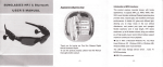
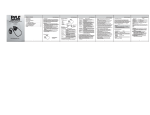
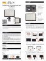
Professional LED Photography Light
o
Utfrium Battery Compartment
Battery Switch
@ O
User Manual
Sonnon
@
DL-913
o
O
Brightness Adjustment Dia
@
Group A Sync Eutton
@ O Group
! Ll.i ca a o..i,i o;+c ?c,} tlc
a tri) :i,' C.i ! U i)tr i a a + J + a ::
a;')r:e ;;;Cra *a! a aa aar
i aC Ja
C i:j] -\a ;: l j:a;a*
i)a,: l. J ICO$i.1,) laaGi,l
taJ.)aiaooac0aiaacl:
,)ac )a o.i30.cia c.,i *a 1
,trriaao:an.ci
c*atoa:
Itotral)aa.nc.c3aa+3:
C
)a e:r a O i (:i it a C aa.: 1 il ( a
i) .)0 3 c cai. ac i c ra a 3,: {1 c
$aat a a,? .:).1 aic a i ., a a a,a C c
B
sync Button
E
Group c Sync Eutton
@ @
@@@@
@
!
-1
a''
a
-)
)
tra
:-t
aJ
a
a
a
a1
a
na
c
@
:o-)
)
-i
;a:
trl
-ff
-J -CC tr
Ctr
O
Flash Setting Button
@
Light tndicator
O
sYNc lnput
@
Power
on/off
6-il DCqv-14v tnout
f
.la.l
]C
.l
ti ) ftr AC a
,at i ii
cC
(:
:)) .C
ac
C
@
ai
,l ('
a
c .C
(l
partment
@
AA Battery Com
@
Barndoor Bracket Holes
@
LED
Lisht Board
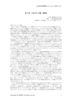
o Barndoor Bracket lnstallation
There arefourbarndoor bGcket holes at each corner ofthe LED Light.Align four male
manual screw of the barndoor bEcket to the frxed hoes of the LED Light and tighten
each one in cl@loise direction. To release, in countercl@kwise direction.You @n easily
adjust the angle of the bamdoor Please pay attention to the order to cover back the
barndoor. You have to fint coverbacktwolongerones and then @veredtvvoshortones.
Before using this product, you must read the manual and fully understand
how to use it and ensure that you can easily handle the operation method
and also use it properly.
3
1
o
prodd E an decimE dftEe. ( may b€ affectHi by *e@l ewiMrerrtalfactoE and
lL This
G@ the @m@ @nd ope6e d rolfurEtir. N*rtlEl6, this possibility is wry small.
A Please do not allow product to strcng vibEtt'on, otheMise, it may Guse the product tdilure
Whentheproductsisnotinuseforalongtime,pleaseturnoffthepowerofdeviceand
aA
removethebateries.
A
The batteries should be installed correctly, Reverse polarity may cause batteries to leak
A
Please
GA corrosive liquids, heat or explosion.
do not store in a high temperature, such as a closed car where under direct sunlight
G}\ the dashboard and other high-temperature
areas.
atr\
Please keep the product
2$
lN
-
Do not use the product near the flammable gases, otheruise, it may cause fire or explosion
Due to the product involved the use of batteries, please use in strict accordance with the
operation of the camera specification. Otherwise, it may cause fire, explosion or even
dry do not touch product in the wet hand. Neither put the produci
into water nor exposed it to the rain. OtheNise, the product cannot work normally.
personal injury.
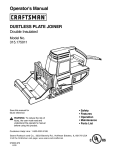
a Hot Shoe Mounting
Name of Each Part
"
.... .
.3
'
Produd lnstallation '
Produd Fundion/How to
specifiGtion.
Align the $rew male diredion to the female of the studio light tripod. Tighten it whh
dod(iliF dirdion. Please ensure the direction of the hot shoe and the studio light is
dre rme. Then, tighten the reinforced wheel in counter clockwise direction.
.2
liems lncluded'
Use
. .
.5
.
l0
.
r)
After opening the packing, please check if all the items below are included. You can contact our
distributor if any item is missing.
DL-913 Main Body
"t
":t
1PC
Barndoor BEcket
lSET
Filter
2PCS
User Manual
1PC
Hot Shoe Wheel
1PC
+s'rc
a The Collocation of Camera or
Camcorder lnstallation
Align and wedge in the studio light with hot shoe installed and the camera or
camcorder hot shoe, then fixed the reinforced wheel by clockwise direction. The
product is lnstalled.
o
@
G
4
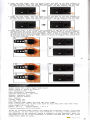
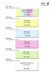
A, B or C was light up, to join other groups, simply press
the group button that you want. To close other groups, simply press the group
button thatyou want. ln case of ABC in the same Eroup, AB in the same group
or AC in the same group, the default of brightness adjustment is under the light
of Group A. lf BC are in the same group, the default of brightness adjustment is
under the light of Group B.There are any groups of lights in groups of the same
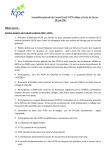
can be adjusted. When you adjust the light as shown in Picture O, the Pictures
@ @ @ will change accordingly. When you adjust the light as shown in Picture
@, the Pictureso O @ will change accordingly. When you adjust the light as
shown in Picture @, the Pictures @ @ @ will change accordingly. When you
adjust the light as shown in Picture @, the Pictures @ @ @ @ will change
5 When either Group
Turn on the power switch after the device is powered. Group A,B,C light indictocwill
light up and turn off automati@lly after 3 se@nds. This means it mds with lml
power and ente6 into the steady mode. lts default is under minimum brightnss@
@
accordingly.
Under
to
the steady mode,
illlrc bdghtE
and
\r'ou cn adjust the tID lEtrt by rccting the adjLsErt daL 6deie
@r,tedodoi* to rcdre brightE. Ihere are 30 l6€b d a4erEE
rI
flsh mode, affEr entering into tE steady mode, prc the flah euing siu$ hrtbn nd
li8lt up the light indizbr, tED lL*t will tum off and enter into ttre fla*r mode. Urds tE Hr
mode , the adjustmert of brighbs is iMlid . Pres the flash sltjng sib*l button €ah , ad
tum off the flash mode, @n restffi the original Etting of steady mode. f
'pu r the f,dr
fundion, \&u ned a PC eble or Pirel King PE tEnsmitter to tElMitslndrlm irstt-dir
(the PC @ble and King Prc tEnsmitter need to be ordered spactely)
UsirE
Steady Synchronous Mode
the wirele$ slnc mode, both (tEnsmitting and reMng) LED liEht reed to
synchronous. First, on the tElMitting tfD light, pl6 and hold G@p A button tH tum
the power on. Rdeas the Grcup A button when the Grcup A indiEto. is fld{.E S€qd,
on the receiving LED litfit, pt6 and hold Grcup B bufton then tum tlE porEr m Relee
the Group B button when the Grcup B indi@tor is flashing.
1. When using
Flash Sync Mode
1. Using flash
function must have a PC cable or Pixel King Pro transmitter
7
The Grcup B indi@tor light willtum offwhen the rynchrcnous is finished. lf lou Ent to
st mutti @ivirg t.ED l€hts, iust Ep€at tiE aboE p.oedue- Ihe tEtMittirt LED light
need to restart s,hen finislr€d the syndlre
tcnsmifting trigger, both (tEnsmitting and receiving) LED light need to
synchronous. Synchronous procedure same as Steady Synchrcnous Mode. Using the PC
to @nnect tEnsmitting LED light and cmeE, also turn on the LED flash settlng
button. Now when you press the shutter release on the GmeE, the LED light which under
the same channeugroup will be triggered. Flash sync setting and steady synchronous
stting are the sme.
2. Using LED light as a
sync cord
the steady mode, prs Co+ A syrE hrtb.r to inn it m ard light up the
light indi@to., ttEn Etate th€ adiuirErt dial lw. Ya cn adi6t tlE brightE
for those lights which rere set to G@p A sync P6 G@p A syrE button again
and to turn it off.
2, Under
3.Using King PRO tENmitter to triggetfirst, Alsoneedtosynchronousfirst.Then, hold
dom the Grup B sync sik}l button of the LID light and blm on the pMr sitcfi
und tne kht irdizttr of grup B lc€p blinhng. Rdeas the G@p B rync sitdr butbn
Ihff, hdd tE C lGry of lftE Prc ard trm s the porer si!d[ ttE display will shw:
CodirE ...whth rc6 tlE dEnrel rEt*fng b pGirE After the dEnnel is mathed
suc$fu|V, Grcup B liglt indiztor of LID liglt will nrm off automati@lly. Nw, ,}eu
hrye to restart the King Po tEnsmitter lf channel matdring is uEucc$fu|, deas
repeat the action. (For King Prc EatuB, pleas refer to King Prc user manual)
Under the steady mode, press Grcup B sync buttm to tum it on and light up the
light indi@tor, then rotate the adjustment dial now. You @n adjust the brightness
for those lights which were set to Grcup B sync Press Grcup B sync button atain
and to turn
it
off.
4.After finished the channel matching, press the flash setting switch and light up
the light indicator to enter into the flash mode.
Under the steady mode, press Grcup C sync button to tum it on and light up the
light indi@tor, then rotate the adjustment dial now. You Gn adjust the brightness
for those lights which were set to Grcup C sync. Press Group C slnc button again
and to turn it off.
the flash mode, open the Group A sync and light up the light indicator
to provide the flash signal. The LED lights which have set as Group A sync will
flash. To close Group A, press the Group A sync switch, the light indicator wil
5. Under
turn
off.
rr)
6
I
6. Under the flash mode, open the 6roup B sync and light up the light indicator to
provide the flash signal. The LED lights which have set as Group B sync will flash
To close Group B, press the Group B sync switch, the light indicator will turn off.
rI
7. Under the flash mode, open the Group C sync and tight up the light indicator to
provide the flash signal. The LED lights whlch have set as Group c sync will flash
To close Group c, press the Group C sync switch, the light indicator will turn off.
rI
8.Under flash mode, if the receiver and transmitter of ABc,AB,Ac or Bcturned on
simultaneously any group of the same will flash.When shown in PictureOtriggers,
the pictures@@Ol@will flash accordingly. When shown in pictureOtriggers, the
pictures@@@will flash accordingly.When shown in PictureG)triggers, the picture
@ @ @ will flash accordingly. When shown in picture @ triggers, the picture @ @
@
will flash accordingly.
o
@
::
@
@
+e
9
a
o
@
Svstem Mode: FSK 2.4GHz Digital Radio System
Group: Group A, Group 8. Group
Color Rendering lndex : )85
C
Color Temperature: 5500Kt200K
Operation Temperature: 20C-50'C
Distance: Maximum 100M
Antenna: lnternal Antenna
LUx:20001m
lrradiate Angle: 60'
LED Lisht: 308 PCS
Flash: Support SYNC Trigger and King PRo Flash Trigger.
Power Consumption: Max 16.8W under stand by mode.Max 25W under flash mode.
Power Supply: AC DC 9V 14V
Battery: AA X
8
Lithium Battery: 7.2V X
2
Product Dimension: 225 X 150 x 48mm
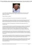
PTXEL product and reading this instruction manual. ,f you have
any questions, you can contact your local distributor or visit http://www. pixelhk. com
Thank for purchasing
This information of this instruction manual is updated as of 18th November, 2013. For
information on the use of the combination of product marketed after this date, please
contact Pixel's dealer for advice.
Pr*!-,
reMr1s
ro
01
10