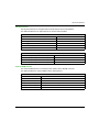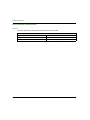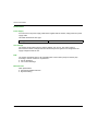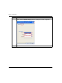
1
SR2MOD02 and SR2MOD03 EIO00000001575 11/2013 SR2MOD02 and SR2MOD03 Wireless Modem User Guide EIO00000001575.00 11/2013 www.schneider-electric.com The information provided in this documentation contains general descriptions and/or technical characteristics of the performance of the products contained herein. This documentation is not intended as a substitute for and is not to be used for determining suitability or reliability of these products for specific user applications. It is the duty of any such user or integrator to perform the appropriate and complete risk analysis, evaluation and testing of the products with respect to the relevant specific application or use thereof. Neither Schneider Electric nor any of its affiliates or subsidiaries shall be responsible or liable for misuse of the information contained herein. If you have any suggestions for improvements or amendments or have found errors in this publication, please notify us. No part of this document may be reproduced in any form or by any means, electronic or mechanical, including photocopying, without express written permission of Schneider Electric. All pertinent state, regional, and local safety regulations must be observed when installing and using this product. For reasons of safety and to help ensure compliance with documented system data, only the manufacturer should perform repairs to components. When devices are used for applications with technical safety requirements, the relevant instructions must be followed. Failure to use Schneider Electric software or approved software with our hardware products may result in injury, harm, or improper operating results. Failure to observe this information can result in injury or equipment damage. © 2013 Schneider Electric. All rights reserved. 2 EIO00000001575 11/2013 Table of Contents Safety Information . . . . . . . . . . . . . . . . . . . . . . . . . . . . . About the Book. . . . . . . . . . . . . . . . . . . . . . . . . . . . . . . . Chapter 1 Introduction. . . . . . . . . . . . . . . . . . . . . . . . . . . . . . . . . . . Product Information . . . . . . . . . . . . . . . . . . . . . . . . . . . . . . . . . . . . . . . Features . . . . . . . . . . . . . . . . . . . . . . . . . . . . . . . . . . . . . . . . . . . . . . . Chapter 2 Package Contents and Labels. . . . . . . . . . . . . . . . . . . . Package Contents and Labels. . . . . . . . . . . . . . . . . . . . . . . . . . . . . . . Chapter 3 General Presentation . . . . . . . . . . . . . . . . . . . . . . . . . . . 3.1 Modem Description . . . . . . . . . . . . . . . . . . . . . . . . . . . . . . . . . . . . . . . Physical Description . . . . . . . . . . . . . . . . . . . . . . . . . . . . . . . . . . . . . . External Connections . . . . . . . . . . . . . . . . . . . . . . . . . . . . . . . . . . . . . Accessories . . . . . . . . . . . . . . . . . . . . . . . . . . . . . . . . . . . . . . . . . . . . . 3.2 Functional Description . . . . . . . . . . . . . . . . . . . . . . . . . . . . . . . . . . . . . Power Supply . . . . . . . . . . . . . . . . . . . . . . . . . . . . . . . . . . . . . . . . . . . RS 232 Serial Link. . . . . . . . . . . . . . . . . . . . . . . . . . . . . . . . . . . . . . . . 3.3 Technical Characteristics . . . . . . . . . . . . . . . . . . . . . . . . . . . . . . . . . . Mechanical Characteristics . . . . . . . . . . . . . . . . . . . . . . . . . . . . . . . . . Electrical Characteristics . . . . . . . . . . . . . . . . . . . . . . . . . . . . . . . . . . . Environmental Characteristics . . . . . . . . . . . . . . . . . . . . . . . . . . . . . . . Standards/Conformities . . . . . . . . . . . . . . . . . . . . . . . . . . . . . . . . . . . . Protections. . . . . . . . . . . . . . . . . . . . . . . . . . . . . . . . . . . . . . . . . . . . . . Chapter 4 Installing the Modem . . . . . . . . . . . . . . . . . . . . . . . . . . . Mounting the Modem . . . . . . . . . . . . . . . . . . . . . . . . . . . . . . . . . . . . . . Removing the Modem . . . . . . . . . . . . . . . . . . . . . . . . . . . . . . . . . . . . . Modem Installation . . . . . . . . . . . . . . . . . . . . . . . . . . . . . . . . . . . . . . . Chapter 5 Modem Communication. . . . . . . . . . . . . . . . . . . . . . . . . 5.1 Verification. . . . . . . . . . . . . . . . . . . . . . . . . . . . . . . . . . . . . . . . . . . . . . Modem Communication Verification . . . . . . . . . . . . . . . . . . . . . . . . . . GSM Receive Signal Quality Verification . . . . . . . . . . . . . . . . . . . . . . PIN Code Verification . . . . . . . . . . . . . . . . . . . . . . . . . . . . . . . . . . . . . Verifying Modem Registration on GSM Network . . . . . . . . . . . . . . . . . 5.2 AT Commands. . . . . . . . . . . . . . . . . . . . . . . . . . . . . . . . . . . . . . . . . . . Main AT Commands (HAYES) . . . . . . . . . . . . . . . . . . . . . . . . . . . . . . Deactivated AT Commands ECHO . . . . . . . . . . . . . . . . . . . . . . . . . . . EIO00000001575 11/2013 5 7 11 12 16 17 17 19 20 21 22 24 26 27 28 29 30 31 34 35 36 37 38 40 41 43 44 45 46 47 48 49 50 51 3 Chapter 6 Troubleshooting . . . . . . . . . . . . . . . . . . . . . . . . . . . . . . . Troubleshooting . . . . . . . . . . . . . . . . . . . . . . . . . . . . . . . . . . . . . . . . . . Appendices . . . . . . . . . . . . . . . . . . . . . . . . . . . . . . . . . . . . . . . . . Appendix A AT Commands . . . . . . . . . . . . . . . . . . . . . . . . . . . . . . . . Basic AT Commands . . . . . . . . . . . . . . . . . . . . . . . . . . . . . . . . . . . . . . Serial Port AT Commands . . . . . . . . . . . . . . . . . . . . . . . . . . . . . . . . . . Call AT Commands . . . . . . . . . . . . . . . . . . . . . . . . . . . . . . . . . . . . . . . Appendix B Modem Configuration . . . . . . . . . . . . . . . . . . . . . . . . . . Reconfiguring the Modem . . . . . . . . . . . . . . . . . . . . . . . . . . . . . . . . . . Glossary . . . . . . . . . . . . . . . . . . . . . . . . . . . . . . . . . . . . . . . . . 4 53 53 57 59 60 66 69 73 73 81 EIO00000001575 11/2013 Safety Information Important Information NOTICE Read these instructions carefully, and look at the equipment to become familiar with the device before trying to install, operate, or maintain it. The following special messages may appear throughout this documentation or on the equipment to warn of potential hazards or to call attention to information that clarifies or simplifies a procedure. EIO00000001575 11/2013 5 PLEASE NOTE Electrical equipment should be installed, operated, serviced, and maintained only by qualified personnel. No responsibility is assumed by Schneider Electric for any consequences arising out of the use of this material. A qualified person is one who has skills and knowledge related to the construction and operation of electrical equipment and its installation, and has received safety training to recognize and avoid the hazards involved. 6 EIO00000001575 11/2013 About the Book At a Glance Document Scope This manual describes how to install, configure, and use the SR2 MOD02 and SR2 MOD03 modems, based on descriptive information and how-to procedures. The modem uses the wavecom module quad-Band version 850/900/1800/1900 MHz (Europe bands: 900/1800 MHz and U.S. bands: 850/1900 MHz) and GSM class 10. This manual describes 2 modem references based upon the controllers supported: Smart relays Zelio logic of Schneider Electric Modem reference: SR2 MOD02 Identified by marking on the modem and the labels Programmable controllers Twido of Schneider Electric Modem reference: SR2 MOD03 Identified by marking on the modem and the labels NOTE: Read and understand this document before installing, operating, or maintaining the SR2 MOD02 and SR2 MOD03 modems. Validity Note This document has been updated with the release of SR2MOD02/03 V1.0. Related Documents For more information refer to the Online Help of Zelio Soft 2 Programming Software and to the Online Help of Twido Suite Programming Software. EIO00000001575 11/2013 7 Product Related Information DANGER HAZARD OF ELECTRIC SHOCK, EXPLOSION OR ARC FLASH Disconnect all power from the equipment including connected devices before removing any covers or doors, installing or removing any accessories, hardware, cables, or wires. Use properly rated voltage sensing device to confirm the power is off. Replace and secure all covers, accessories, hardware, cables, and wires and confirm that a proper ground connection exists before applying power to the unit. Use only the specified voltage when operating this equipment and any associated products. Failure to follow these instructions will result in death or serious injury. Electrical equipment should be installed, operated, serviced, and maintained only by qualified personnel. No responsibility is assumed by Schneider Electric for any result arising out of the use of this material. WARNING UNINTENDED EQUIPMENT OPERATION Only use software approved by Schneider Electric for use with this equipment. Update your application program every time you change the physical hardware configuration. Failure to follow these instructions can result in death, serious injury, or equipment damage. WARNING LOSS OF CONTROL The designer of any control scheme must consider the potential failure modes of control paths and, for certain critical control functions, provide a means to achieve a safe state during and after a path failure. Examples of critical control functions are emergency stop and overtravel stop, power outage and restart. Separate or redundant control paths must be provided for critical control functions. System control paths may include communication links. Consideration must be given to the implications of unanticipated transmission delays or failures of the link. Observe all accident prevention regulations and local safety guidelines.(1) Each implementation of this equipment must be individually and thoroughly tested for proper operation before being placed into service. Failure to follow these instructions can result in death, serious injury, or equipment damage. 8 EIO00000001575 11/2013 1 For additional information, refer to NEMA ICS 1.1 (latest edition), "Safety Guidelines for the Application, Installation, and Maintenance of Solid-State Control" and to NEMA ICS 7.1 (latest edition), "Safety Standards for Construction and Guide for Selection, Installation, and Operation of Adjustable-Speed Drive Systems" or their equivalent governing your particular location. EIO00000001575 11/2013 9 10 EIO00000001575 11/2013 SR2MOD02 and SR2MOD03 Introduction EIO00000001575 11/2013 Chapter 1 Introduction Introduction Overview This chapter describes the various features and the specific regulations of the SR2 MOD02/03 modem. What Is in This Chapter? This chapter contains the following topics: Topic Page Product Information 12 Features 16 EIO00000001575 11/2013 11 Introduction Product Information General This equipment contains Licensed Transmitter FCC ID N7NQ2687, IC ID 2417C-Q2687. This device complies with Part 15 of the FCC Rules. Operation is subject to the following two conditions: 1. this device may not cause harmful interference, and 2. this device must accept any interference received, including interference that may cause undesired operation. It is necessary to follow the specific regulations for the use of radio operator equipment. In particular the possible risks of radio frequency interference (RFI). Restrictions of use for radio operator equipment in: Fuel depots. Chemical factories. Locations where demolition is under way. Other places where signs indicate that the use of cellular telephones is prohibited or dangerous. DANGER POTENTIAL FOR EXPLOSION Install and use this equipment in non-hazardous locations only. Do not disconnect equipment unless power has been switched off or the area is known to be non-hazardous. Failure to follow these instructions will result in death or serious injury. This equipment has been tested and found to comply with the limits for a Class B digital device, pursuant to part 15 of the FCC Rules. These limits are designed to provide reasonable protection against harmful interference in a residential installation. This equipment generates, uses and can radiate radio frequency energy and, if not installed and used in accordance with the instructions, may cause harmful interference to radio communications. However, interference may occur in a given or particular installation nonetheless. If this equipment does cause harmful interference to radio, television or other communication device transmission/reception, which can be determined by turning the equipment off and on, the user is encouraged to try to correct the interference. 12 EIO00000001575 11/2013 Introduction WARNING ELECTROMAGNETIC INTERFERENCE Reorient or relocate the modem antenna if you experience communication interference with other devices. Increase the separation distance between equipment subject to electromagnetic interference and the modem / antenna. Connect equipment subject to electromagnetic interference into a power outlet on a circuit different from that to which the modem is connected. Consult your local Schneider Electric representative if you are unable to resolve electromagnetic interference issues that may arise in conjunction with the use of the modem. Failure to follow these instructions can result in death, serious injury, or equipment damage. This equipment complies with FCC’s radiation exposure limits set forth for an uncontrolled environment under the following conditions: 1. This equipment should be installed and operated such that a minimum separation distance of 20.3 cm (8 in) is maintained between the radiator (antenna) and the body of the user or nearby person at all times. 2. This transmitter must not be collocated or operating in conjunction with any other antenna or transmitter. WARNING ELECTROMAGNETIC RADIATION EXPOSURE Do not operate the modem, or have the antenna placed, within 20.3 cm (8 in) of anyone. Do not use any other antenna than that supplied with the modem. Do not share the use of the modem antenna with any other device. Do not locate the modem antenna in proximity to another antenna or radio transmitting device. Failure to follow these instructions can result in death, serious injury, or equipment damage. There can be a hazard associated with the use of your GSM modem close to insufficiently protected medical devices such as acoustic apparatus and pacemakers. Consult the manufacturers of medical equipment to determine if they are adequately protected. If the equipment is insufficiently protected, then the use of your GSM modem in close proximity to other electronic equipment can also cause interference. Observe all recommendations for the equipment from the manufacturer. EIO00000001575 11/2013 13 Introduction WARNING UNINTENDED EQUIPMENT OPERATION Do not use this product in safety critical machine functions. Use approved appropriate hard-wired safety interlocks where personnel and/or equipment hazards exist. Do not disassemble, repair, or modify the products. Use this equipment only in a properly rated enclosure. Use a 2.5 A, 250 V fuse designed to Type F standards as per IEC 60127 that are UL recognized and CSA approved for the power supply line. Failure to follow these instructions can result in death, serious injury, or equipment damage. CAUTION INOPERABLE EQUIPMENT Do not open the modem housing. Return the modem to the seller in case any damage is detected. Failure to follow these instructions can result in injury or equipment damage. Power Supply The modems require a power supply rated between 5.5 and 32 Vdc. To conform to UL and CSA regulations, the power supply must be of a type Class III SELV (Safety Extra Low Voltage) certified and conforming to CSA/UL 60950-1 (2nd Edition). The power supply must be isolating, grounded (earthed) and current limited to a maximum of 100 VA. DANGER HAZARD OF ELECTRIC SHOCK, EXPLOSION OR ARC FLASH Do not connect the equipment directly to line voltage. Use only Class III, isolated SELV limited energy power supply not to exceed 100 VA. Failure to follow these instructions will result in death or serious injury. 14 EIO00000001575 11/2013 Introduction Care and Maintenance NOTICE UNINTENDED MAINTENANCE EQUIPMENT Do not expose the modem to the extreme environments such as a high temperature or a high humidity content. Do not use or store the modem in dusty or dirty places. Do not open or disassemble the modem. Do not expose the modem to liquids. Avoid dropping, striking, or shaking the equipment violently. Do not place the modem near computer disks, credit or voyage cards, or other magnetic media. Failure to follow these instructions can result in equipment damage. EIO00000001575 11/2013 15 Introduction Features Modem Features The table shows the various features of the SR2 MOD02/03 modem: Modem GSM functions Quad-bands 900/1800 MHz and 850/1900 MHz ETSI GSM phase 2+: Class 4 (2 W at 850/900 MHz) Class 1 (1 W at 1800/1900 MHz) SIM toolkit release 99 Data features Supports PBCCH, coding schemes: CS1 and CS4 TCP/IP Library (PPPRFC, TCP socket, UDP socket, SMTP, POP3, FTP) Asynchronous data circuit, transparent, and non-transparent, 9600 bps (standard) up to 14,400 bps (depending on network) Compatible fax group 3 SMS point-to-point MT/MO and SMS CB Memory type interfaces Flash 32 Mbits and SRAM 4 Mbits (32/4) Interfaces Antenna GSM: SMA-F connector Power supply: 5.5...32 Vdc (micro-FIT connector) RS 232 via female 9-pin SUB-D connector AT commands: GSM 07.05 and 07.07 SIM reader (SIM 3 V–1.8 V) DIN (35 mm) Rail mounting clip Supplied accessories Mounting brackets (x 2) Power supply cable - 2-wire micro FIT GSM magnetic antenna (SMA-M) 16 EIO00000001575 11/2013 SR2MOD02 and SR2MOD03 Package Contents and Labels EIO00000001575 11/2013 Chapter 2 Package Contents and Labels Package Contents and Labels Package Contents and Labels Overview This figure illustrates the contents included in the modem package: 1 2 3 4 5 6 The SR2 MOD02/03 modem. DIN 35 mm (1.38 in.) rail mounting clip. 2 mounting brackets. Instruction Sheet. 2-wire power cable (Red/Black) with in-line fuse (2.5 A/250 V). GSM magnetic antenna with connection cable (2500±100 mm) and SMA male connector. EIO00000001575 11/2013 17 Package Contents and Labels 18 EIO00000001575 11/2013 SR2MOD02 and SR2MOD03 General Presentation EIO00000001575 11/2013 Chapter 3 General Presentation General Presentation Overview This chapter describes the modem description, functional description, and technical characteristics of the SR2 MOD02/03 modem. What Is in This Chapter? This chapter contains the following sections: Section Topic Page 3.1 Modem Description 20 3.2 Functional Description 26 3.3 Technical Characteristics 29 EIO00000001575 11/2013 19 General Presentation Section 3.1 Modem Description Modem Description Overview This section provides information about the physical description, external connections, and accessories of the SR2 MOD02/03 modem. What Is in This Section? This section contains the following topics: Topic 20 Page Physical Description 21 External Connections 22 Accessories 24 EIO00000001575 11/2013 General Presentation Physical Description Description of the Modem This figure provides the description of the modem: 1 2 3 4 5 6 7 8 Micro FIT 3.0TM female 4-pin connector for the electrical supply Female sub D 9-Pin connector for RS 232 Front side Optional DIN rail mounting clip Rear side SMA female antenna connector: The GSM antenna connector is a 50 Ω impedance female SMA type SIM card cover GSM modem activity LED EIO00000001575 11/2013 21 General Presentation External Connections GSM Antenna Connector The GSM antenna connector is a 50 Ω impedance female SMA type. 4-Pins Micro FIT Female Connector The connector allows the connection of an external DC supply. This table describes the connector pin assignment: Pin Assignment Pin Number Signal 1 5.5...32 Vdc 2 0 Vdc 3 N.C. 4 N.C. WARNING UNINTENDED EQUIPMENT OPERATION Do not connect wires to unused terminals or terminals marked “Not Connected (N.C.)”. Failure to follow these instructions can result in death, serious injury, or equipment damage. 22 EIO00000001575 11/2013 General Presentation 9-Pins Sub D Female Connector The table describes the connector pin assignment: Pin Assignment EIO00000001575 11/2013 Pin Number Pin Name Circuit (V24 - RS232C) I/O 1 Signal detection DCD O 2 Data reception RXD O 3 Data transmission TXD I 4 Data terminal ready DTR I 5 Protective earth ground GND – 6 Data set ready DSR O 7 Request to send RTS I 8 Clear to send CTS O 9 Ring indicator RI O 23 General Presentation Accessories 2-Wires Micro FIT Supply Cable This figure illustrates the cable supplied with the modem: 1 2 3 4 5 Molex connector micro FIT 3.0 Black wire (0 Vdc) Red wire (+Vdc) Fuse 2.5 A/250 V fast blow (5 x 20 mm/0.2 x 0.79 in.) Tinned copper wire This figure describes how to connect the cable to the modem: This figure describes how to disconnect the cable from the modem: This table illustrates the connector from cable side and describes its components and characteristics: View Component Characteristics 4-pins micro FIT connector Type: Molex Cable 1500 mm (59.1 in.) Wire section/Gauge Tinned copper 24 x 0.2 mm (0.94 x 0.01 in.) Surface area: 0.75 mm2 (18 AWG) 24 EIO00000001575 11/2013 General Presentation GSM Magnetic Antenna (SMA-M) The GSM magnetic antenna is designed for vertical installation on a metallic support. Its SMA male connection allows it to be directly connected to the modem. This table illustrates the GSM magnetic antenna and describes its components and characteristics: View EIO00000001575 11/2013 Component Characteristics SMA-M antenna Quad-bands: 850/900/1800/1900 MHz Cable 2500±100 mm (59.1±3.94 in.) Coaxial RG174 - Ø 2.54 mm (Ø 0.10 in.) Dimensions Base: Ø 30 mm (Ø 1.18 in.) Total height: Ø 70 mm (Ø 2.76 in.) 25 General Presentation Section 3.2 Functional Description Functional Description Overview This section provides information about the power supply and RS 232 serial link of the SR2 MOD02/03 modem. What Is in This Section? This section contains the following topics: Topic 26 Page Power Supply 27 RS 232 Serial Link 28 EIO00000001575 11/2013 General Presentation Power Supply Description Use an external, regulated DC power source designated as Class III, Safety Extra Low Voltage (SELV) between 5.5...32 Vdc to power the modem (V+BATTERY). An internal DC/DC converter provides the modem with internal DC voltages. The modem will not function correctly if the input voltage (V+BATTERY) falls below 5.5 Vdc. NOTE: An in-line 2.5 A/250 V fast blow fuse in the power supply cable supplied with the modem helps protect the power supply cable. It also helps protect the modem against power supply spikes of more than 32 Vdc. Filter specifications: Input/output EMI/RFI protection Signal smoothing EIO00000001575 11/2013 27 General Presentation RS 232 Serial Link General The RS 232 interface provides a level translation between the GSM module (DCE) and the PC COM port (DTE). The RS 232 interface is secured internally (ESD shielding) against external electrostatic spikes. Filter specifications: Input/output EMI/RFI reduction Signal smoothing The following signals are available in this link: TX data (TX) RX data (RX) Request to send (RTS) Clear to send (CTS) Data terminal ready (DTR) Data set ready (DSR) Data carrier detect (DCD) Ring indicator (RI) This figure illustrates the signals exchanged by the modem: NOTE: The RS 232 interface allows a certain amount of flexibility in the use of its signals. For example, the modem operates in the 3-wire mode using only the TX, RX and GND signals. Mode Autobaud The auto-baud mode allows the modem to detect the transmission speed used by the DTE. Only the following speeds are detected: 2400, 4800, 9600, 19,200, 38,400 bps, and 57,600 bps. Autobaud detection is not reliable for speeds below or above the given values. The auto-baud mode is controlled by the AT commands. To see this function explained in detail, refer to the description of the AT baud rate command (see page 66) in Appendix A. 28 EIO00000001575 11/2013 General Presentation Section 3.3 Technical Characteristics Technical Characteristics Overview This section provides information about the mechanical, electrical, and environmental characteristics and the standards/conformities of the SR2 MOD02/03 modem. What Is in This Section? This section contains the following topics: Topic Page Mechanical Characteristics 30 Electrical Characteristics 31 Environmental Characteristics 34 Standards/Conformities 35 Protections 36 EIO00000001575 11/2013 29 General Presentation Mechanical Characteristics General This table describes the mechanical characteristics of the modem: Mechanical Characteristics Dimensions 73 x 54.5 x 25.5 mm (2.87 x 2.14 x 1 in.) (without connectors) Overall dimensions 90 x 54.5 x 25.5 mm (3.54 x 2.14 x 1 in.) Weight 88 g (3.1 oz) (modem only) < 335 g (11.8 oz) (modem and accessories) Volume 101.5 cm3 (39.96 in.3) Case Extruded aluminum Ingress protection IP31 This figure describes the dimensions of the modem and the clearances necessary for installation: 30 EIO00000001575 11/2013 General Presentation Electrical Characteristics Power Supply The operating voltage range is between 5.5...32 Vdc. To conform to UL and CSA regulations, the power supply must be of a type Class III SELV (Safety Extra Low Voltage) certified and conforming to CSA/UL 60950-1 (2nd Edition). The power supply must be isolating, grounded (earthed) and current limited to a maximum of 100 VA. DANGER HAZARD OF ELECTRIC SHOCK, EXPLOSION OR ARC FLASH Do not connect the equipment directly to line voltage. Use only Class III, isolated SELV limited energy power supply not to exceed 100 VA. Failure to follow these instructions will result in death or serious injury. NOTE: The modem remains under power as long as it is connected to a power supply that is itself under power. If the Voltage: Then < 5.5 Vdc GSM communication cannot operate properly. > 32 Vdc (transient peaks) The modem has built-in protection. EIO00000001575 11/2013 31 General Presentation Power Supply Consumption This table describes the power supply consumption (1) of the modem without the RS 232 connected: CONDITIONS T = 25 ºC (77 ºF) and 3 Vdc SIM Card Idle mode (2) Idle mode 32 K (3) In communication GSM 1RX/1TX Power (2 W/1 W) During TX bursts Power (2 W/1 W) 850/900 MHz 1800/1900 MHz I Nominal (mA) I Maximal (mA) I Nominal (mA) I Maximal (mA) 5.5 V 17.5 23 17.5 23 12 V 11.7 16.5 11.7 16.5 24 V 10 14 10 14 32 V 8.6 11.5 8.6 11.5 5.5 V 12 14.5 12 14.5 12 V 9.2 11.3 9.2 11.3 24 V 8 10.5 8 10.5 32 V 7.7 9.7 7.7 9.7 5.5 V 182.5 195.5 135 145 12 V 96 103.5 71.75 78 24 V 50 54 37 40 32 V 40 44.5 31 34.75 5.5 V 1178 1400 670 780 12 V 600 712 342 400 24 V 320 375 180 220 32 V 230 274 132 156 (1) The power consumption can vary by 5% over the whole operating temperature range –20 ºC...55 ºC (–68...131 ºF). (2) Idle mode: The modem is registered on the network but not in communication. (3) Idle mode 32 K: The low-power mode controlled by an external application via the DTR CTS signals. Electrical Characteristics of the SIM Interface The electrical characteristic of the SIM card is 1.8 Vdc or 3 Vdc. GSM/DCS Frequency Bands This table describes the frequency ranges: 32 Parameter GSM 850 E-GSM 900 DCS 1800 PCS 1900 Transmission frequency 824...849 MHz 880...915 MHz 1710...1785 MHz 1850...1990 MHz Reception frequency 869...894 MHz 925...960 MHz 1805...1880 MHz 1930...1990 MHz EIO00000001575 11/2013 General Presentation RF Performances The RF performances are compliant with the ETSI GSM 05.05 recommendation. This table describes the RF performances for receiver and transmitter: Receiver E- GSM900/GSM850 reference sensitivity –104 dBm DCS1800/PCS1900 reference sensitivity –102 dBm Selectivity @ 200 kHz > 9 dBc Selectivity @ 400 kHz > 41 dBc Linear dynamic range 63 dB Co-channel rejection ≥ 9 dBc Transmitter at Ambient Temperature Maximum output power (E-GSM900/GSM850) 33 dBm ±2 dB Maximum output power (DCS1800/PCS1900) 30 dBm ±2 dB Minimum output power (E-GSM900/GSM850) 5 dBm ±5 dB Minimum output power (DCS1800/PCS1900) 0 dBm ±5 dB External GSM Antenna The external GSM antenna is connected to the modem via the SMA/M connector. This table describes the external GSM antenna characteristics: External GSM Antenna Characteristics Antenna frequency range Quad-bands 850/900/1800/1900 MHz Impedance 50 Ω nominal DC impedance 0Ω Gain (antenna + cable) 0 dBi (in a minimum direction) VSWR (Rx max TX max) 1.5:1 Polarization Linear EIO00000001575 11/2013 33 General Presentation Environmental Characteristics General This table describes the environmental characteristics of the modem: Environmental Characteristics 34 Operating temperature –20...55 ºC (–68...131 ºF) Storage temperature –40...70 ºC (–104...158 ºF) Operating humidity without condensation HR < 95% at 55 ºC (131 ºF) EIO00000001575 11/2013 General Presentation Standards/Conformities Description The product conforms to the following requirements: R&TTE 1999/5/EC directive Regulations of standard ETSI EN 301 489-7, EN 301 419-1, and EN 301 511 2002/96/CE DEEE The modem conforms to the 2002/95/CE - RoHS requirements. The modems conform to standards described in the Declaration of Conformity which can be found at www.schneider-electric.com. EIO00000001575 11/2013 35 General Presentation Protections Power Supply An in-line fuse in the power supply cable that is supplied with the modem, helps protect the power supply cable. This table describes the fuse type: Fuse type FSD 2.5 A/250 V FAST Over-Voltage The modem design helps protect it against voltages over 32 Vdc. The power supply is disconnected in order to help protect the internal components against over-voltage when the supply voltage exceeds 32 Vdc. ESD The modem withstands ESD on all accessible parts of the modem (except for the RF part) according to the IEC 61000-4-2 requirements: 8 kV air discharge 4 kV contact discharge Miscellaneous Filter specifications: Input/output EMI/RFI reduction Signal smoothing 36 EIO00000001575 11/2013 SR2MOD02 and SR2MOD03 Installing the Modem EIO00000001575 11/2013 Chapter 4 Installing the Modem Installing the Modem Overview This chapter describes how to mount, install, and remove the SR2 MOD02/03 modem. What Is in This Chapter? This chapter contains the following topics: Topic Page Mounting the Modem 38 Removing the Modem 40 Modem Installation 41 EIO00000001575 11/2013 37 Installing the Modem Mounting the Modem Mounting Using DIN Rail Mounting Clip The modem is supplied with a DIN rail mounting clip mounted on the case. The DIN rail mounting clip allows mounting on a DIN Rail IEC/EN 60715/DIN 35 x 7.5 mm (1.38 x 0.3 in). Execute step 1 (pressure) to mount the modem on DIN rail, then step 2 (pivot). This figure describes the step 1 and step 2 of mounting the modem: Mounting Procedure Using 2 Mounting Brackets Use the supplied mounting brackets when surface mounting the modem as shown in the given figure: 1 Mounting brackets Refer also to the drilling dimensions (see page 30). NOTE: The modem has to be mounted to a flat surface when applying the mounting brackets. The maximum height of the screw head is 2 mm. 38 EIO00000001575 11/2013 Installing the Modem This table describes the removal of the mounting brackets: Step Action 1 Remove the DIN rail mounting clip before installing the surface mounting brackets. 2 Remove the 2 mounting clips retaining the screws. 3 Slide the mounting clip off the modem. EIO00000001575 11/2013 39 Installing the Modem Removing the Modem Removing Using DIN Rail Mounting Clip The DIN rail mounting clip allows removal of the modem from a DIN rail IEC/EN 60715/DIN 35 x 7.5 mm (1.38 x 0.3 in). Execute step 3 (pressure) to remove the modem from the DIN rail, then steps 4 and 5 (pivot and remove). This figure describes the steps 3, 4, and 5 of removal procedure: 40 EIO00000001575 11/2013 Installing the Modem Modem Installation Description To install the modem, perform the following operations with the modem turned off: Remove the SIM card cover on the rear side. Insert the SIM card into its holder. Replace and secure the SIM card cover. Connect the antenna to the SMA connector. Connect the 9-pin sub D connector of the modem to the controller using a cable. Connect the power supply cable to an external, regulated DC power source. Connect the power supply cable to the modem and activate the power supply. The modem selects the network band and the GSM LED illuminates. The modem is now ready to be configured. Refer to AT Commands (see page 49) for the description of the commands. Network Bands Scanning With the SIM card installed and after applying power, the modem automatically scans the European network bands in order to select the proper frequency. In case such a frequency cannot be established, the modem will then start to scan the North American network bands. This cycle is repeated until a valid network is found. After detection of the GSM network, it is saved in the memory of the modem. If the SIM card is replaced with another, this procedure will be automatically reinitialized. NOTE: If the modem frequency is selected for use in a specific area (Europe for instance), and is then introduced in a different area (the U.S., for instance), remove and replace the SIM card while the modem is still under power. This action causes the modem to detect that a reinitialization is required even if the same SIM card is reinserted back in the modem. EIO00000001575 11/2013 41 Installing the Modem GSM LED Status The GSM LED that is located on the side of the modem (see page 21) indicates the state of the modem. This table provides the meaning of the different states of the GSM LED (see page 21): GSM LED LED Activity Modem State ON LED on The modem is powered and is ready to function, but has not yet been recognized by the network. This occurs when the PIN code has not been entered or the antenna is not connected. LED flashing (once every 2 seconds) The modem is powered and the PIN code is active. The network recognizes the modem and is ready to make or receive a call (Idle mode). OFF 42 LED flashing (once a second) The modem is powered and currently in communication (Voice, data, or fax). LED off The modem is not powered or is in the RESET phase. EIO00000001575 11/2013 SR2MOD02 and SR2MOD03 Modem Communication EIO00000001575 11/2013 Chapter 5 Modem Communication Modem Communication Overview This chapter describes the verifications and the AT commands in SR2 MOD02/03 modem. What Is in This Chapter? This chapter contains the following sections: Section Topic Page 5.1 Verification 44 5.2 AT Commands 49 EIO00000001575 11/2013 43 Modem Communication Section 5.1 Verification Verification Overview This section provides the verifications necessary for the SR2 MOD02/03 modem. What Is in This Section? This section contains the following topics: Topic 44 Page Modem Communication Verification 45 GSM Receive Signal Quality Verification 46 PIN Code Verification 47 Verifying Modem Registration on GSM Network 48 EIO00000001575 11/2013 Modem Communication Modem Communication Verification General Description Connect the RS 232 on the PC COM port. Configure the DTE RS 232 port according to the type of the modem, as described in the table: Parameters Description Zelio Logic (SR2 MOD02) Twido (SR2 MOD03) Data rate 115200 bauds 19200 bauds Data size 7 bits 8 bits Parity Even parity No parity Stop bits 1 Stop bit 1 Stop bit Flow control hardware flow control activated hardware flow control deactivated AT commands echo Echo deactivated Echo deactivated DSR signal DSR 1 DSR OFF Ring register S0 = 0 (no automatic answer) S0 = 2 (answer after 2 rings) Enter the command AT(CR) with the Windows hyperterminal communication application. The modem responds with OK. If the modem does not respond, then: Verify the RS 232 connection between DTE and the modem (DCE). Verify the configuration of the COM port on the DTE. Examples of AT Commands Some of the AT commands that can be sent to the modem once the communication is established and verified are given here: AT+CGSN: The modem responds with a 15-digit number. AT+CPIN = xxxx: Enter the code of the SIM card xxxx (if active). AT+CSQ: Verify the GSM signal reception level. AT+CREG?: Verify the registration of the modem on the network. ATD<telephone number>: Start a voice call. ATH: Hang-up (end the call). For more information about AT commands and their associated parameters, refer to Appendix A (see page 59). EIO00000001575 11/2013 45 Modem Communication GSM Receive Signal Quality Verification General Description The modem establishes a call, only if the received GSM signal is of a sufficient level. The AT+CSQ command restores the reception level (rssi) of the signal sent by the closest GSM base transceiver station (BTS), and the receive bit error rate (ber). The command AT+CSQ restores the signal level from the BTS on the subscribed operator network when it is used with a SIM card and the PIN code is entered. The use of this command without a SIM card simply indicates the closest BTS, as the modem cannot identify the current subscription. Thus it is advisable to do this test with the SIM card present. AT+CSQ Command and Responses Enter the command AT+CSQ, using a communication application to verify the GSM signal quality. The response is +CSQ: <rssi>,<ber>, where: <rssi> = indicates the reception level <ber> = receive bit error rate This table lists the values to verify the <rssi> value: <rssi> Value Gain (dBm) Interpretation <ber> Value Interpretation 0 –113 dBm Insufficient 0...7 See standard ETSI GSM 05.08 1...10 –111...–95 dBm Insufficient – – 11...30 –95...–53 dBm Sufficient – – 31 (max) –51 dBm Ideal – – 99 – Unknown/not detectable 99 Unknown/not detectable Reception Level for the Modem The GSM will function properly with a minimum <rssi> value from 11...15. The signal value below 10 is insufficient. The modem cannot function depending on the geographical situation or the mobility of the vehicle. The signal value above 15 is sufficient to establish a connection. For more information about AT commands, refer to Appendix A (see page 59). 46 EIO00000001575 11/2013 Modem Communication PIN Code Verification General Description The PIN code is necessary to make or receive a call from the GSM network. You can modify the PIN code and it is stored on the SIM card. AT+CPIN? Command and Response Enter the command AT+CPIN?, using a communication application to verify the previously entered PIN code. This table describes the main responses from the modem: Command Response Interpretation AT+CPIN? +CPIN: ERROR The SIM card is absent or unknown. +CPIN: READY The PIN code is correct. +CPIN: SIM PIN The PIN code is incorrect or not yet entered +CPIN: SIM PUK The PUK code is required For more information about AT commands, refer to Appendix A (see page 59). EIO00000001575 11/2013 47 Modem Communication Verifying Modem Registration on GSM Network General Description For this verification, confirm that a valid SIM card is present in the SIM card reader of the modem. AT Commands for Modem Registration Verification Enter the given AT commands, using a communication application: AT+CPIN = xxxx: Enter the PIN code with the command. The operator has 3 attempts to enter the PIN code correctly. After the third attempt, only the PUK code (supplied by the operator) allows a new PIN code to be entered. AT+CREG?: This verifies the network registration status. The response is in the format +CREG: <mode>,<stat>, where: <Mode> = unsolicited registration message configuration <Stat> = registration status This table describes the main responses from the modem: Command Response Interpretation AT+CREG? +CREG: 0,0 The modem is not recognized by the network. +CREG: 0,2 The modem is searching for a network operator. +CREG: 0,1 The modem is GSM attached to a local operator. +CREG: 0,5 The modem is GSM attached to an operator in roaming mode. NOTE: If the modem does not register, verify the antenna connection and the receive signal level. For more information about AT commands, refer to Appendix A (see page 59). 48 EIO00000001575 11/2013 Modem Communication Section 5.2 AT Commands AT Commands Overview This section provides information about the AT commands that is used for configuring and using the SR2 MOD02/03 modem. What Is in This Section? This section contains the following topics: Topic Page Main AT Commands (HAYES) 50 Deactivated AT Commands ECHO 51 EIO00000001575 11/2013 49 Modem Communication Main AT Commands (HAYES) Description This table describes the main AT commands useful for the control of the modem: Description AT Command Response Interpretation Enter the PIN code AT+CPIN = xxxx (xxxx = PIN code) OK PIN code accepted +CME ERROR: 16 PIN code incorrect(1) +CME ERROR: 3 PIN code already entered(1) +CREG: 0,1 The modem is GSM attached to a local operator +CREG: 0,5 The modem is GSM attached to an operator in roaming mode +CREG: 0,2 The modem is searching for a network operator +CREG: 0,0 The modem is not recognized by the network OK Reply to the call Verification of GSM network registration Reception of an AT+CREG? ATA incoming call(2) OK ATD<telephone number>; +CME ERROR: 11 NOTE: The semicolon at the end of the sequence +CME ERROR: 3 specifies a voice call. Communication established Make an emergency call (112) ATD112; OK Communication established Lost communication – NO CARRIER – Hang-up ATH OK – Make a voice call PIN code not entered There is no credit or the communication has already been established (1) The AT command AT+CMEE = 1 allows display of extended detected error codes. The AT command AT+WIND = 63 allows display of the change of status of the SIM card and to check states of the modem drivers. (2) The AT command AT+CRC = 1 displays more detailed ring information indicating call type (voice, data, or fax) of an incoming call. These commands are saved with the command AT&W. For example: For VOICE: +CRING: VOICE, for DATA: +CRING: REL ASYNC, and for FAX: +CRING: FAX For more information about AT commands, refer to Appendix A (see page 59). 50 EIO00000001575 11/2013 Modem Communication Deactivated AT Commands ECHO Description In case no echo returns, when the operator enters an AT command, it could be that: The echo function of the modem is deactivated (setting by default). The local echo of the communication application is not activated. NOTE: The echo is configured by the command ATE and requires a back-up with the command AT&W. Activation of Modem Echo Enter the command ATE to activate the modem echo. Execute the given actions when using a communication application to send AT commands to the modem: Deactivate the local echo in your communication application. Activate the modem echo (enter the command ATE1). NOTE: For a communication machine to machine with the modem, it is recommended to deactivate the modem echo (enter the command ATE0) to avoid the CPU from getting redundant responses. For more information about the echo AT command refer to Appendix A (see page 66). EIO00000001575 11/2013 51 Modem Communication 52 EIO00000001575 11/2013 SR2MOD02 and SR2MOD03 Troubleshooting EIO00000001575 11/2013 Chapter 6 Troubleshooting Troubleshooting Troubleshooting Removing Power of the Unit It is ill-advised to remove power to the modem while in communication or dialog without first finishing the communication and then detaching from the network. CAUTION LOSS OF DATA Do not intentionally remove power to the modem and/or the control system that it is connected to during on-going communications over the modem. Failure to follow these instructions can result in injury or equipment damage. To help avoid network congestion when it is required to remove power from the modem, it is necessary to follow the given steps: Execute the command AT+CPOF. In case this is not done correctly, the modem can remain registered on the network. Send the command AT+CPOF or AT+CFUN = 0 (identical functions) before removing power in dialog mode (no communication). The modem returns OK and is no longer registered on the network. The radio module shifts into the standby mode and then the power is removed. EIO00000001575 11/2013 53 Troubleshooting RS 232 (V24) Communication Troubleshooting The table describes a list of possible causes and solutions, in case the modem does not respond to any of the AT commands via the RS 232: Modem Returns Verify Action Nothing The modem is correctly powered. Ensure that the modem is connected to an external regulated power source between 5.5...32 Vdc. For more details, refer Power supply (see page 27). The serial cable is connected at both ends (PC and modem). Verify the connection of the serial cable. The serial cable is correctly wired. Refer to the Table (see page 22) describing the connector pin assignment of 4-pins micro FIT female connector. Wire the serial cable. Refer to the Table (see page 22) describing the connector pin assignment of 4-pins micro FIT female connector. The communication terminal is correctly configured on the PC. Ensure that the terminal configuration corresponds to that of the modem. Refer to the Modem Communication Verification (see page 45) for factory configuration. Nothing or random characters There is no other application using the Close the conflicting application. same port thus creating a conflict. The modem echo is deactivated and without message reporting. Enter the command ATE1Q0 followed by AT&W if a backup is required. ERROR Message The modem returns the message ERROR (in response to an AT command) in the given cases: The COM port is not directed to the modem but to another modem. Enter the command AT1. The response is WAVECOM MODEM. All other responses indicate a dialog with another modem. Verify the COM port used in the communications application. The syntax of the AT command is incorrect. Re-enter the command. (Refer to Appendix A (see page 59) for a list of AT commands). When the syntax of the AT command is correct, but with incorrect parameters follow the given steps: Enter the command AT+CMEE = 1 to obtain a detected error message with its detected error code instead of the simple ERROR message Enter the AT command which previously caused an inaccuracy to obtain the detected error code again. In the case of an error found, the response is in the form: +CME ERROR: <error code> or +CMS ERROR: <error code> For more information about detected error codes returned by the command AT+CMEE, refer to Appendix A (see page 59). NOTE: It is advised to let the modem return detected error codes (enter the command AT+CMEE = 1). 54 EIO00000001575 11/2013 Troubleshooting NO CARRIER Message The table describes a list of possible causes and solutions, in case the modem responds with the NO CARRIER message after an attempted call: Modem Returns Verify That Action NO CARRIER The received GSM signal is strong enough. Verify the received signal quality. Refer the GSM Receive Signal Quality Verification (see page 46). The modem is registered on the network. Verify network registration. Refer the Modem Registration Verification (see page 48). The antenna is correctly connected. Check the GSM antenna installation. The semi-colon (;) has been NO CARRIER (when attempting a entered immediately after the telephone number in the AT voice call) command. Ensure that the semi-colon (;) has been entered immediately after the telephone number in the AT command. For example: ATD0123456789 The SIM card is configured for NO CARRIER (when attempting a data/fax calls. data call) The selected modulation type is supported by the called number. Ensure that the SIM card is allowed to make data/fax calls (check with the SIM card supplier). The selected modulation type is supported by the network. Ensure that the selected modulation type is supported by the called number. Ensure that the selected modulation type is supported by the network. If not, select a compatible modulation type with the command AT+CBST = 0,0,1 .(1) 1 For further information concerning AT commands, refer to Appendix A (see page 59). Use the command AT+CEER to see the extended found error codes. EIO00000001575 11/2013 55 Troubleshooting This table describes a list of detected error codes and their meanings: Error Code Description Observations 1 Unassigned (unallocated) number – 16 Normal call clearing – 17 User busy – 18 No user responding – 19 User alerting, no answer – 21 Call rejected – 22 Number changed – 31 Normal, unspecified – 50 Requested facility not subscribed Check the subscription (data subscription availability). 68 ACM ≥ ACMmax No more SIM card or credit card expired. 252 Call barring on outgoing calls – 253 Call barring on incoming calls – 3, 6, 8, 29, 34, 38, 41, 42, 43, 44, 47, 49, 57, 58, 63, 65, 69, 70, 79, 254 Network cause Refer to Appendix A (see page 59) or check with the operator. NOTE: For codes and information, refer to Appendix A (see page 59). 56 EIO00000001575 11/2013 SR2MOD02 and SR2MOD03 EIO00000001575 11/2013 Appendices What Is in This Appendix? The appendix contains the following chapters: Chapter Chapter Name Page A AT Commands 59 B Modem Configuration 73 EIO00000001575 11/2013 57 58 EIO00000001575 11/2013 SR2MOD02 and SR2MOD03 AT Commands EIO00000001575 11/2013 Appendix A AT Commands AT Commands Overview This appendix describes commonly used AT command based messages between an application and the SR2 modems. For mor information about AT commands, refer to the “AT® Commands Interface Guide for Open AT Firmware V6.63” at http://www.ercogener.com. What Is in This Chapter? This chapter contains the following topics: Topic Page Basic AT Commands 60 Serial Port AT Commands 66 Call AT Commands 69 EIO00000001575 11/2013 59 AT Commands Basic AT Commands Introduction This topic describes the following basic AT command based messages between an application and the SR2 modems: Attention Command (see page 60) Repeat Last Command (see page 60) Manufacturer Identification (see page 61) Hardware Version (see page 61) Request Revision Identification (see page 61) Request Identification Information (see page 61) Save Configuration (see page 63) Restore Factory Settings (see page 64) Restore Configuration from non-volatile memory (see page 64) Display Configuration (see page 64) Address Type Selection (see page 65) Attention Command The Attention Command queries the modem to affirm that it is present and in communication with the application. Command Format Command Example Response Example AT AT OK Repeat Last Command The Repeat Last Command repeats the last command of the open session. NOTE: The A/ command itself cannot be repeated. If the Repeat Last Command is the first command of the open session, the response is OK without any treatment. 60 Command Format Command Example Response Example A/ A/ OK EIO00000001575 11/2013 AT Commands Manufacturer Identification This command returns the identification of the manufacturer of the communication module. If the Manufacturer Identification command is the first command of the open session, the response is OK without any treatment. Command Format Command Example Response Example AT+CGMI AT+CGMI Sierra Wireless OK Hardware Version This command returns the hardware version of the communication module. Command Format Command Example Response Example AT+WHWV AT+WHWV Hardware Version 4.14 OK Request Revision Identification This command returns the firmware version of the embedded module. Command Format Command Example Response Example AT+CGMR AT+CGMR R7.43.0.201003261552.WMP5 0 2139952 032610 15:52 OK Defined Values: SW release Software release version number WCPU Type of module embedded size Firmware size in bytes date Date (mmddyy) of firmware generation time Time (hh:mm) of firmware generation Request Identification Information This command returns specific information on one or more lines of text concerning the embedded module. Command Format Command Example Response Example ATI<n> ATI6 DATA RATES: AUTOBAUD,300,1200,1200/75, 2400,4800,9600,14400 EIO00000001575 11/2013 61 AT Commands Defined Values: 0 Embedded module with the 2nd core: display manufacturer identification (equivalent to +CGMI, refer to these commands for more precision) Embedded module without the 2nd core: display manufacturer followed by model identification (equivalent to +CGMI and +CGMM, refer to these commands for more precision) 3 Display revision identification (equivalent to +CGMR) 4 Display embedded module configuration in RAM (equivalent to &V0) 5 Display embedded module configuration in EEPROM (equivalent to &V1) 6 Display embedded module data features. Lists the supported data rates, data modes and fax classes 7 Display embedded module voice features 8 Embedded module with the 2nd core: display software version followed by the chip Id Embedded module without the 2nd core: “OK” 62 EIO00000001575 11/2013 AT Commands 9 Display component details: Downloader, Firmware, embedded Open® AT application (Developer Studio version used to build it, Integrated Plug In version), memory. The response is divided into four groups: <Component> <Version>[, <Name>, <Company>, <Size>, <TimeStamp>, <Checksum>, <Offset>] [-<SubComponent>, <SubComponentVersion>] <MemoryType>, <MemorySize> [<InfoTage>, <InfoValue>] Parameter Data type Description <Component> ascii string embedded software component type; values: "DWL", "FW", "OAT", "3G+" <Version> ASCII string version of the software component <Name> ASCII string component name <Company> ASCII string component company <Size> integer component size in bytes <TimeStamp> ASCII string component time stamp <Checksum> ASCII string component check sum <Offset> ASCII string offset address of the component <SubComponent> ASCII string subcomponent name: this field is filled by Developer Studio (supported from version 1.1) <SubComponent Version> ASCII string subcomponent version: this field is filled by Developer Studio (supported from version 1.1) <MemoryType> ASCII string “ROM” or “RAM” <MemorySize> integer size of the <MemoryType> in bytes, in hexadecimal, set at the upper roundish value (100000 = 8 Mb, 200000 = 16 Mb, 400000 = 32 Mb, 800000 = 64 Mb, …) <InfoTag> ASCII string Information Tag, the value is the parameter <InfoValue>. Current supported value: "DWLNAME") <InfoValue> ASCII string Information Value. For "DWLNAME" information Tag: Type of the correct DWL file type to be downloaded in the embedded module, based on the product name.) Save Configuration This command writes the active configuration to non-volatile memory (EEPROM). Command Format Command Example Response Example AT&W AT&W OK EIO00000001575 11/2013 63 AT Commands Restore Factory Settings This command restores configuration settings to the factory default values. Command Format Command Example Response Example AT&F AT&F OK Restore Configuration from non-volatile memory This command restores the previously saved configuration from non-volatile memory (EEPROM). Command Format Command Example Response Example ATZ ATZ OK Display Configuration This command returns the saved configuration of the embedded module. Command Format Command Example Response Example AT&V[<n>] AT&V Q:0 V:1 S0:000 S2:043 S3:013 S4:010 S5:008 +CR:0 +CRC:0 +CMEE:0 +CBST:0,0,1 +SPEAKER:0 +ECHO:1,4 &C:1 &D:2 %C:0 +IPR:9600 +ICF:3,4 +IFC:2,2 NOTE: In the command format, <n> is an optional parameter. Defined Values: 0 Display the embedded module configuration in RAM (default value if no parameter provided) 1 Display the embedded module configuration in EEPROM 2 Display the embedded module factory configuration NOTE: The +IPR value is not returned when <n> = 2. 64 EIO00000001575 11/2013 AT Commands Address Type Selection This command specifies the type of number for dialing commands according to GSM specifications. Command Format Command Example Response Example AT+CSTA=<type> AT+CSTA=145 OK NOTE: In the above example, the international access code character "+" will be automatically added to the outgoing call. Defined Values: 129 ISDN / telephony numbering plan, national / international unknown. The ‘+’ must be added to the number for international calls; otherwise it is assumed to be a national number.) 145 ISDN / telephony numbering plan, international number. Number is assumed to be international and will automatically have the ‘+’ added to the dialing string. NOTE: The +IPR value is not returned when <n> = 2. EIO00000001575 11/2013 65 AT Commands Serial Port AT Commands Introduction This topic describes the following serial port AT command based messages between an application and the SR2 modems Echo (see page 66) Fixed DTE Rate (baud rate) (see page 66) Character Framing (see page 68) Echo This command is used to determine whether the embedded module echoes characters received by the application: Command Format Command Example Response Example ATE[<n>] ATE1 OK NOTE: In the above example, the international access code character "+" will be automatically added to the outgoing call. Defined Values: 0 Characters are not echoed (default value if <n> omitted). 1 Characters are echoed. NOTE: The <n> parameter is stored in EEPROM using the Save Configuration (see page 63) (AT&W) command. Fixed DTE Rate (baud rate) This command specifies the data rate at which the embedded module will accept commands: Command Format Command Example Response Example ATE+IPR=<rate> ATE+IPR=9600 OK NOTE: In the above example, the data rate is set to 9600 bps. 66 EIO00000001575 11/2013 AT Commands Defined Values: 0 Enables autobauding. 300 – 600 – 1200 – 2400 – 4800 – 9600 – 19200 – 38400 – 57600 – 115200 Command default value. 230400 – 460800 – 921600 – NOTE: The <n> parameter is stored in EEPROM using the Save Configuration (see page 63) (AT&W) command. When starting up, if autobaud is enabled and no Attention (see page 60) (AT) command has yet been received, the product sends all unsolicited responses (like RING) at 9600 bauds. The serial autobaud feature is supported, and covers the following serial speeds (only): 1200, 2400, 4800, 9600, 19200, 38400, 57600, 115200, 230400, 460800, 921600 bps. Beyond those serial speeds, correct operation of the embedded module is not supported. Any AT command issued by the DTE must start with both capital ‘A’ and ‘T, (or ‘/’) or both lower case ‘a’ and ‘t’ (or ‘/’), otherwise the DCE may return some characters and become desynchronized. If this happens, the DTE simply issues ‘AT\r’ (at 2400 or 4800 baud) once or twice or just ‘AT’ (at 9600 baud) to resynchronize the embedded module. The DTE waits for 1ms after receiving the last character of the AT response (which is always ‘\n’ or 0x0A) to send a new AT command at either the same rate or a new rate. If this delay is ignored, the DCE can become desynchronized. Once again, sending ‘AT\r’ once or twice or just ‘AT’ causes the DCE to recover. EIO00000001575 11/2013 67 AT Commands Character Framing) This command is used to determine the local serial port start-stop (asynchronous) character framing used by the embedded module: Command Format Command Example Response Example ATE+ICF=<format>,[<parity>] ATE+IPR=9600 OK NOTE: In the command format, <parity> is an optional parameter. In the above example, the response is 8 data bits, 1 parity, 1 stop, odd parity. Defined Values: <format> 1 8 data, 2 stop, <parity> parameter is ignored 2 8 data, 1 parity, 1 stop, if no <parity> provided 3 is used by default as <parity> value. 3 8 data, 1 stop, <parity> parameter is ignored. This is the default value. 4 7 data, 2 stop, <parity> parameter is ignored. 5 7 data, 1 parity, 1 stop, if no <parity> provided, 3 (space) is used by default as <parity> value. 6 7 data, 1 stop, <parity> parameter is ignored. <parity> 0 Odd 1 Even 2 Mark 3 Space 4 None. This is the default value. NOTE: The <format> and <parity> parameters are stored in EEPROM using the Save Configuration (see page 63) (AT&W) command, and the default values can be restored using the restore factory settings (see page 64) (AT&F) command. 68 EIO00000001575 11/2013 AT Commands Call AT Commands Introduction This topic describes the following call AT command based messages between an application and the SR2 modems: Dial Command (see page 69) Redial Last Telephone Number (see page 71) Answer Incoming Call (see page 71) Hang-Up Call (see page 71) Automatic Answer (see page 71) Dial Command This command is used to dial an outgoing call to a specific number. It also allows an application to dial emergency call numbers and specify emergency call codes. According to 3GPP specifications, only several numbers should be considered as emergency numbers: without a SIM: 112, 911, 000, 08, 110, 999, 118 and 119 with a SIM: 112, 911 and numbers present in the EFECC SIM file All others numbers will be considered as GSM numbers. The ATD command is used to set a voice, data or fax call. As per GSM 02.30, the dial command also controls supplementary services. The following emergency numbers are available without a SIM card: 000, 08, 110, 112, 118, 119, 911 and 999. The following Emergency Numbers are available with a SIM card: when EFECC file is missing from SIM: 112 and 911 when SIM includes an EFECC file: 112, 911 and any emergency numbers available in the EFECC file Command Format Command Example Response Example ADT<nb>,[<I>] [<G>] [;} ATD+33412345678 CONNECT 9600 NOTE: In the above example, the data call succeeds. EIO00000001575 11/2013 69 AT Commands Defined Values: <nb> Destination phone number (ASCII string) or GSM sequence 0-9,*,#,+,A,B,C,D,P <I> CLIR supplementary service subscription. If present, the CLIR supplementary service subscription is overridden temporarily for this call only: I = activate (disable presentation of own phone number to remote) i = deactivate (enable presentation of own phone number to remote) <G> CUG supplementary service information. If present, the CUG supplementary service information is overridden temporary for this call only: G = activate g = deactivate <;> Indicates a voice call. If omitted, data or fax call is assumed NOTE: For an international number, the local international prefix does not need to be set (usually 00) but must be replaced by the ‘+’ character. Note that some countries may have specific numbering rules for their GSM handset numbering. An outgoing call attempt can be refused if the AOC service is active and credit has expired (NO CARRIER). As per GSM 02.30, GSM sequences may be controlled using dial commands. These sequences can contain “*", “#", but “;" is forbidden in the sequence. For example, to invoke or suppress CLIR service temporally, ATD*31#<nb>[;] and ATD#31#<nb>[;] can be used (with „;? at the end, a voice call will be launched). If the FDN phonebook is activated, the call forwarding sequences are allowed only if they are present in the FDN. A category can be filled for an emergency call. To use this specificity, the following syntax should be used: ATD<nb>#<category> where: <nb> is the emergency call <category> is a bit field with the following description: - bit 1: police - bit 2: ambulance -bit 3: fire brigade - bit 4: marine guard - bit 5: mountain rescue - bit 6: manually initiated e-call - bit 7: automatically initiated e-call - bit 8: reserved, set to “0” The <category> range is [1-127]. If an out of range value is filled and if the <nb> is an emergency call, this field is not taken into account by the embedded module and the emergency call is initiated (without this information). If the <nb> number is not an emergency number, the <category> field is not taken into account and a normal call is initiated by the embedded module. If bit 6 and bit 7 are set to 1, the embedded module automatically set bit 6 to 0 and keep bit 7 to 1. 70 EIO00000001575 11/2013 AT Commands Redial Last Telephone Number This command is used by the application to redial the last number used in the dial command: Command Format Command Example Response Example ATDL ATDL 0033412345678 OK Answer Incoming Call When the product receives a call, it sets the Ring Indicator signal and sends the ASCII "RING" or "+CRING: <type>" string to the application (+CRING if the cellular result code +CRC is enabled). Then it waits for the application to accept the call with the ATA command: Command Format Command Example Response Example ATA ATA OK Hang-Up Call The ATH (or ATH0) command is used by the application to disconnect the remote user. In the case of multiple calls, all calls are released (active, on-hold and waiting calls): Command Format Command Example Response Example ATH[<n>] ATH OK Defined Values: 0 Ask for disconnection. 1 Ask for outgoing call disconnection. Automatic Answer This command determines and controls the product automatic answering mode: Command Format Command Example Response Example ATS0[<value>] ATS0=3 OK NOTE: In the example, an automatic answer occurs after three rings. Defined Values: <value> EIO00000001575 11/2013 The number of rings before automatically answering a call. 71 AT Commands 72 EIO00000001575 11/2013 SR2MOD02 and SR2MOD03 Modem Configuration EIO00000001575 11/2013 Appendix B Modem Configuration Modem Configuration Reconfiguring the Modem Modem Configuration Your SR2 MOD02/03 modem comes pre-configured from the factory for use with either the Zelio or Twido controllers. However, if you need to edit the default modem configuration, or if the modem loses its configuration, refer to the following procedure for reconfiguring your modem. For more information, refer to Modem Communication Verification (see page 45). This table describes the steps to follow to add a modem using Windows: Step Action 1 Select the Start menu. 2 In the Control Panel, select Phone and Modem Options. 3 Click Modems then click Add. EIO00000001575 11/2013 73 Modem Configuration Step 74 Action 4 Select the Don’t detect my modem; I will select it from a list checkbox and click Next to continue. 5 Select Standard 56000 bps Modem from the Models list and click Next to continue. EIO00000001575 11/2013 Modem Configuration Step 6 EIO00000001575 11/2013 Action Select the communication port where the modem is connected and click Next to proceed to the next window. 75 Modem Configuration Step 7 76 Action After installation, it is necessary to configure the communication port link to the modem. Select the Standard 56000 bps Modem from the modem list and click Properties tab. EIO00000001575 11/2013 Modem Configuration Step 8 EIO00000001575 11/2013 Action Click the Modem menu tab in the Standard 56000 bps Modem Properties window. Set 115200 as the Maximum Port Speed. 77 Modem Configuration Step 9 78 Action Select the Advanced menu tab in the Standard 56000 bps Modem Properties window and click Change default preferences. EIO00000001575 11/2013 Modem Configuration Step 10 EIO00000001575 11/2013 Action Click the General menu tab on the Standard 56000 bps Modem Default Preferences window. Set the Port Speed and Flow control to 115200 and None respectively. 79 Modem Configuration Step 80 Action 11 Click the Advanced menu tab on the Standard 56000 bps Modem Default Preferences window. Enter the Hardware settings parameters according to the modem configuration (see page 45) (for SR2MOD02 and SR2MOD03). 12 Restart the PC and modem. EIO00000001575 11/2013 SR2MOD02 and SR2MOD03 Glossary EIO00000001575 11/2013 Glossary A AC alternative current ACM accumulated call meter AT attention (prefix for modem commands) B BTS base transceiver station C CLK clock CMOS complementary metal oxide semiconductor CS coding scheme CTS clear to send D dB decibel dBc decibel relative to the carrier power dBi decibel relative to an isotropic radiator dBm decibel relative to one milli-watt EIO00000001575 11/2013 81 Glossary DC direct current DCD data carrier detect DCE data communication equipment DCS digital cellular system DSR data set ready DTE data terminal equipment DTMF dual tone multi-frequency DTR data terminal ready E E-GSM extended GSM EEPROM electrically erasable programmable read-only memory EFR enhanced full rate EMC electromagnetic compatibility EMI electromagnetic interference ESD electrostatic discharges ETSI European telecommunications standards institute 82 EIO00000001575 11/2013 Glossary F FIT series of connectors (micro-FIT) FR full rate FTA full type approval G GCF global certification forum GND protective ground GPIO general-purpose input output GSM global system for mobile communications H HR half rate I I input I/O input / output IEC international electrical commission IMEI international mobile equipment identification EIO00000001575 11/2013 83 Glossary L LED light emitting diode Little-endian low-order byte of the number is stored in memory at the lowest address, and the high-order byte at the highest address. M MAX maximum ME mobile equipment MIC microphone MICRO FIT family of connectors from Molex MIN minimum MNP Microcom networking protocol MO mobile originated MS mobile station MT mobile terminated N NOM nominal O O output 84 EIO00000001575 11/2013 Glossary P Pa pascal (for speaker sound pressure measurements) PBCCH packet broadcast control channel PC personal computer PCL power control level PDP packet data protocol PIN personal identity number PLMN public land mobile network PUK personal unblocking key R RF radio frequency RFI radio frequency interference RI ring indicator RMS root mean square RTS request to send RX receive EIO00000001575 11/2013 85 Glossary S SIM subscriber identification module SMA subminiature version A RF connector SMS short message service SNR signal-to-noise ratio SPI serial peripheral interface SPK speaker SPL sound pressure level SRAM static RAM T TDMA time division multiple access TPC/IP transmission control protocol / Internet protocol TU typical urban fading profile TUHigh typical urban, high speed fading profile TX transmit TYP typical 86 EIO00000001575 11/2013 Glossary U UTC universal time clock V VSWR voltage stationary wave ratio EIO00000001575 11/2013 87