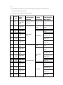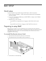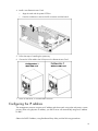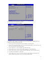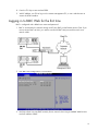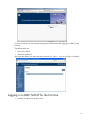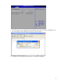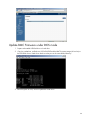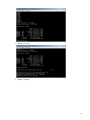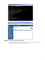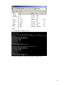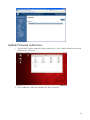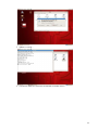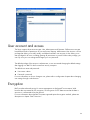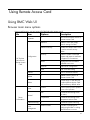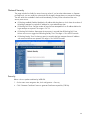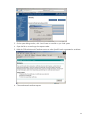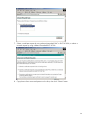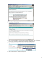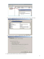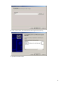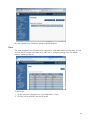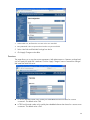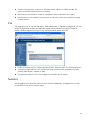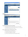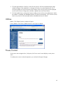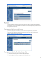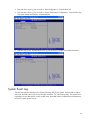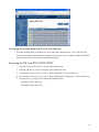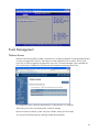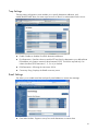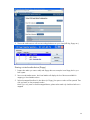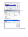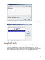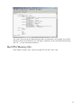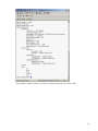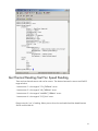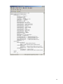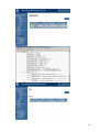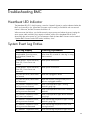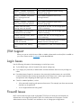
1
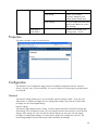
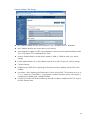
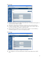
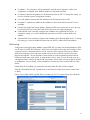
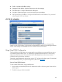
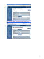
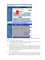
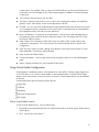
HP MicroServer Remote Access Card User Manual Part Number: 664489-003 November 2014 Edition: 3 © Copyright 2011, 2014 Hewlett-Packard Development Company, L.P. The information contained herein is subject to change without notice. The only warranties for HP products and services are set forth in the express warranty statements accompanying such products and services. Nothing herein should be construed as constituting an additional warranty. HP shall not be liable for technical or editorial errors or omissions contained herein. Linux® is the registered trademark of Linus Torvalds in the U.S. and other countries. Microsoft® and Windows® are U.S. registered trademarks of the Microsoft group of companies. Intended audience This document is for the person who installs, administers, and troubleshoots servers and storage systems. HP assumes you are qualified in the servicing of computer equipment and trained in recognizing hazards in products with hazardous energy levels. Contents Operational Overview .......................................................................................................................... 5 Guide Overview ......................................................................................................................................... 5 BMC Overview ........................................................................................................................................... 5 Server management through IPMI version 2.0 compliant applications .......................................................... 5 IPMI Messaging Interfaces ...................................................................................................................... 5 Sensors ................................................................................................................................................. 6 External Event Generation ....................................................................................................................... 6 LAN Messaging ..................................................................................................................................... 6 Platform Event Filtering (PEF) and Alert Policies .......................................................................................... 8 Firmware Firewall .................................................................................................................................. 8 Browser interface overview ..................................................................................................................... 8 Supported browsers and client operating systems ...................................................................................... 8 Supported server operating system software ............................................................................................. 8 BMC SETUP ........................................................................................................................................ 9 Quick setup ................................................................................................................................................ 9 Preparing to setup BMC ............................................................................................................................... 9 To reinstall the Remote Access Card ......................................................................................................... 9 Configuring the IP address .................................................................................................................... 10 Logging in to BMC Web for the first time................................................................................................ 13 Logging in to BMC SMCLP for the first time ............................................................................................. 14 Configuring BMC ............................................................................................................................... 17 BMC Firmware Update User Guide ............................................................................................................ 17 Update BMC Firmware via Web UI ....................................................................................................... 17 Update BMC Firmware under DOS mode ............................................................................................... 20 Update Firmware under Windows ......................................................................................................... 22 Update Firmware under Linux ................................................................................................................ 24 User account and access ........................................................................................................................... 26 Encryption ................................................................................................................................................ 26 Using Remote Access Card .................................................................................................................. 27 Using BMC Web UI .................................................................................................................................. 27 Browser main menu options .................................................................................................................. 27 Properties ............................................................................................................................................ 28 Configuration ...................................................................................................................................... 28 Network ................................................................................................................................... 28 Network Security ....................................................................................................................... 32 Security..................................................................................................................................... 32 Users ........................................................................................................................................ 38 Services .................................................................................................................................... 39 IPMI.......................................................................................................................................... 40 Sessions .............................................................................................................................................. 40 Update ............................................................................................................................................... 41 Preparation before online firmware flashing.................................................................................. 41 Start to update firmware of Remote Access Card ........................................................................... 41 Utilities................................................................................................................................................ 42 Power/Control ..................................................................................................................................... 42 Thermal .............................................................................................................................................. 43 3 Viewing sensor data from a web browser ..................................................................................... 43 Viewing sensors data from Rom-Based setup utility ........................................................................ 43 System Event Log ................................................................................................................................. 44 Accessing the system event log from a web browser ...................................................................... 45 Accessing the SEL from BIOS SETUP UTILITY ................................................................................. 45 Event Management .............................................................................................................................. 46 Platform Events .......................................................................................................................... 46 Trap Settings ............................................................................................................................. 47 Email Settings ............................................................................................................................ 47 vKVM & vMedia .................................................................................................................................. 48 Using Virtual KVM Configuration ................................................................................................. 48 Using Virtual Media Configuration............................................................................................... 51 Using BMC SMCLP ................................................................................................................................... 54 Get CPU/Memory Info ......................................................................................................................... 55 Get Thermal Reading/Get Fan Speed Reading ....................................................................................... 57 Get Fan Status ..................................................................................................................................... 60 SMCLP Power Control Function.............................................................................................................. 61 Frequently Asked Questions (FAQ) ....................................................................................................... 62 Recovering a BMC username and password ................................................................................................ 62 Verifying that the BMC firmware is functioning ............................................................................................. 63 Recovering from a BMC firmware crash ...................................................................................................... 63 How to configure BMC .............................................................................................................................. 63 Troubleshooting BMC ......................................................................................................................... 64 Heartbeat LED Indicator ............................................................................................................................. 64 System Event Log Entries ............................................................................................................................ 64 JVM Support ............................................................................................................................................. 65 Login Issues .............................................................................................................................................. 65 Firewall Issues .......................................................................................................................................... 65 Proxy server issues .................................................................................................................................... 66 Glossary ........................................................................................................................................... 67 4 Operational Overview Guide Overview The Remote Access Card provides multiple ways to configure, update, and operate servers remotely. This Remote Access Card User Guide describes these features and how to use them with the browserbased interface and RBSU. The SMASH CLP is designed for users who prefer a non-graphical interface. The SMASH CLP chapter describes the syntax and the ways to remote control server. BMC Overview BMC can remotely perform most functions that otherwise require a visit to servers at the data center, computer room, or remote location. The following are just a few examples of using BMC features. BMC Remote Console and virtual power enables you to view a stalled remote server with blue screen conditions and restart the server without onsite assistance. BMC Virtual KVM technology provides a high-performance remote console that enables you to remotely administer operating systems and applications in everyday situations. BMC virtual CD/DVD-ROM or floppy enables you to install an operating system or flash system firmware over the network from images on your workstations or on centralized web servers. BMC actively participates in monitoring and maintaining server health, referred to as embedded health BMC monitors temperatures in the server and sends corrective signals to the fans to maintain proper server cooling. In addition to temperature monitoring, BMC provides fan status monitoring. Server management through IPMI version 2.0 compliant applications Server management through the IPMI is a standardized method for controlling and monitoring the server. BMC provides server management based on the IPMI version 2.0 specification. The IPMI specification defines a standardized interface for platform management. The IPMI specification defines the following types of platform management: Monitoring of system information, such as fans, temperatures Recovery capabilities, such as system resets and power on/off operations Logging capabilities, for abnormal events such as over temperature readings or fan failures Inventory capabilities, such as identifying failed hardware components. IPMI Messaging Interfaces IPMI messaging interfaces will comply with IPMI v2.0, and supported interfaces include IPMI Messaging interfaces, Keyboard Controller Style (KCS) interface and IPMI LAN interface. The KCS 5 interface provides a set of I/O mapped communications registers. The default system base address for the I/O mapped KCS Interface is 0xCA2 and is byte aligned at this system address. The KCS interface is accessible to SMS software that is running on the local system. Examples of compatible SMS software applications are as follows: IPMI version 2.0 Command Test Tool is a low-level MS-DOS command line tool that enables hex formatted IPMI commands to be sent to an IPMI BMC that implements the KCS interface. You can locate this tool on the Intel® website (http://www.intel.com/design/servers/ipmi/tools.htm). IPMI tool is a utility for managing and configuring devices that support the IPMI version 1.5 and version 2.0 specifications and can be used in a Linux environment. You can locate this tool on the IPMI tool website (http://ipmitool.sourceforge.net/index.html). Before using Linux ipmitool via system interface, please make sure installing Linux ipmi driver (Use the shell command “service ipmi start”). Sensors The BMC provide environmental monitoring through IPMI sensors. Sensors will be described in the SDR repository (IPMI v2.0, Chapter 33 SDR Repository) and can be accessed through the IPMI sensor device commands (IPMI v2.0, Chapter 35 Sensor Device Commands). System configuration can be discovered through exploration of the SDR repository. IPMI provides a sixteen byte string identifier in each SDR. This ASCII based string will need to be interpreted by system management software. These tokens will be used in the SDR string identifier field and will provide any distinction needed in addition to the other fields of the SDR. External Event Generation The BMC is configured to send its alerts to another event receiver in the system. See IPMIv2.0 Chapter 29 Event Commands for more information. All events commands which are mandatory for an event generator are implemented in the BMC firmware. LAN Messaging The BMC will use on chip NIC to provide support for IPMI messaging over LAN. IPMI messages will be sent as RMCP packets by on chip NIC, which will pass the messages to the BMC via on chip NIC where the BMC will receive and respond to the messages. See the IPMIv2.0 specification Chapter 13 IPMI LAN Interface for more information. Four simultaneous LAN sessions will be supported. There is no limitation on the number of concurrent sessions for a single user. All mandatory IPMI LAN messaging commands are implemented in the BMC Core Firmware. Section 18.1 of this document contains the list of supported optional LAN messaging commands. RMCP+ is supported under IPMI 2.0. This protocol enhancement conforms to the overall RMCP format. Extensions allow for multiple payload types, enhanced authentication, and encryption. Details can be found in IPMIv2.0 section 13.3 RMCP+. IPMI Firmware supported optional encryption methods as below table (ID 0~14): 6 Key: S = authenticated session setup (correct role, username and password/key required to establish session) A = authenticated payload data supported. E = authentication and encrypted payload data supported. ID Charac teristic s Cipher Suite 0 “no passwor d" 00h, 00h, 00h 1 S 01h, 00h, 00h 2 S, A 01h, 01h, 00h 3 S, A, E 01h, 01h, 01h 4 S, A, E 01h, 01h, 02h 5 S, A, E 01h, 01h, 03h 6 S 02h, 00h, 00h 7 S, A 02h, 02h, 00h 8 S, A, E 02h, 02h, 01h 9 S, A, E 02h, 02h, 02h 10 S, A, E 02h, 02h, 03h 11 S, A 02h, 03h, 00h None 12 S, A, E 02h, 03h, 01h AES-CBC-128 13 S, A, E 02h, 03h, 02h 14 S, A, E 02h, 03h, 03h Authentication Integrity Confidentiality Algorithm Algorithm(s) Algorithm(s) RAKP-none None None None None None RAKP-HMACSHA1 HMAC-SHA196 AES-CBC-128 xRC4-128 xRC4-40 None None None HMAC-MD5128 RAKP-HMAC-MD5 AES-CBC-128 xRC4-128 xRC4-40 MD5-128 xRC4-128 xRC4-40 7 Platform Event Filtering (PEF) and Alert Policies PEF (IPMIv2.0, Chapter 17 Platform Event Filtering) will be supported to allow alerting in response to configured system events. On the HP MicroServer platform, the following event filters and alert policies will be implemented by default. Any additional filters or alert policies desired by the user must be configured using the Set PEF Configuration Parameters command discussed in Section 30.3 of the IPMIv2.0. Firmware Firewall The BMC supports firmware firewall which is an IPMI v2.0 optional capability that is supported on all BMC implementations. Details can be found in the IPMI v2.0 specification Chapter 21. Browser interface overview The BMC browser interface groups similar tasks for easy navigation and workflow. These tasks are organized under high-level tabs across the top of the BMC interface. These tabs are always visible and include Option, Properties, Configuration, Sessions, Update, Utilities, Power control, Thermal, System event log, VKVM&VMedia. Each high-level BMC tab has a menu on the left side of the interface with various options. This menu changes every time you select a different high-level tab, displaying the options available from that tab. Each menu option displays a page title, which is a description of the information or settings available on that page. This page title might not reflect the name displayed on the menu option. Assistance for all BMC pages is available from BMC Help. Links on each BMC page provide summary information about the features of BMC and helpful information to optimize its operation. To access page specific help, click the help link (Help) on the top and right side of the browser window. Supported browsers and client operating systems Microsoft® Internet Explorer 8 Microsoft® Internet Explorer 7 Microsoft® Internet Explorer 6 Firefox 3.x Firefox 2.0 The web server support both HTTP and HTTPS protocols Supported server operating system software BMC is an independent microprocessor running an embedded operating system. The architecture ensures that the majority of BMC functionality is available, regardless of the host operating system. 8 BMC SETUP Quick setup To quickly setup BMC using the default settings for BMC features, follow the steps below: 1. Prepare the hardware installation — Refer to the MicroServer Remote Access Card Installation Instructions for detail 2. If you are not using dynamic IP addressing, use the BIOS RBSU to configure a static IP address (“Configuring the IP address”). 3. Methods for Log in: Users can either: - Log into BMC from a supported browser (“Logging in to BMC Web for the first time”). or - Log into SMCLP via a SSH client. (“Logging in to BMC SMCLP for the first time”) Preparing to setup BMC Before setting up your BMC, you must install Remote Access Card and remove VGA cable from embedded VGA connector to VGA connector on the Remote Access Card. Since the server will export VGA signal via the VGA connector on this card automatically when the Remote Access Card is plugged (BIOS default setting). To reinstall the Remote Access Card 1. Open the chassis and remove the system tray out of the chassis. 2. Lift the Remote Access Card to release it from the connector (1). 3. Put the card into an anti-statistic bag. 9 4. Install a new Remote Access Card: • Align the card with the system PCIE slot • Press the card down to ensure the full connection with the board. 5. Follow the steps of installing the system tray. 6. Connect the VGA cable to the VGA port on the Remote Access Card. 7. Power on the server, it will have BMC functions. Configuring the IP address The management processor acquires an IP address and subnet mask using either a dynamic or static process. When using dynamic IP address, your DHCP server will automatically assign an IP address for BMC. Obtain the DHCP IP address, using Rom-Based Setup Utility with the following procedures: 10 1. Power on the server by pressing the Power on/Off button on the front panel 2. When POST prompts the message “press F10 for Rom-based setup Utility”, press the F10 key, the main screen of the BIOS Setup Utility appears 3. Press the right arrow (→) key to navigate to the “Advanced” menu. 4. Press the down arrow (↓ ) key to scroll to “IPMI Configuration”. Press the “Enter” key. 5. Press the down arrow (↓ ) key to scroll the “Set LAN Configuration” menu. Press the “Enter” key. 11 6. Set the “BMC LAN Configuration” to “DHCP” 7. Press the F10 key to save and exit RBSU To configure a static IP address, use the RBSU with the following procedure to disable DHCP and configure the IP address and the subnet mask: 1. Power on the server by pressing the Power on/Off button on the front panel 2. When POST prompts the message “press F10 for Rom-based setup Utility”, press the F10 key, the main screen of the BIOS Setup Utility appears 3. Press the right arrow (→) key to navigate to the “Advanced” menu. 4. Press the down arrow (↓ ) key to scroll to “IPMI Configuration”. Press the Enter key. 5. Press the down arrow (↓ ) key to scroll the “Set LAN Configuration” menu. Press the Enter key. 6. On “BMC LAN Configuration”, select “static” 7. Press the down arrow (↓ ) key to scroll down and enter a valid IP address, subnet mask, and gateway address (press period (.) key to move between address fields). 12 8. Press the F10 key to save and exit RBSU. 9. With IP address, use SSH to log in to the remote management CLP, or use a web browser to access the HTML interface. Logging in to BMC Web for the first time BMC is configured with a default user name and password. 1. BMC is connected to the network through a NIC port (RJ45) on the Remote Access Card. If you want to access BMC via LAN, you need to connect the BMC LAN port and the switch via a network cable. 2. Get “BMC LAN configuration” from the RBSU 3. Use these values to access BMC remotely from a network client using a standard Web browser via the IP address of BMC. 13 For security reasons, HP recommends changing the default settings after logging in to BMC for the first time. The default values are: • User name—admin • Password—password After input the default user name and password and click “sign in”, then you will log it successfully. Logging in to BMC SMCLP for the first time 1. Get BMC IP address first as last section. 14 2. User SSH client to connect the BMC via the IP address. Enter the “Host Name” (IP address), and the “User Name” (such as admin).Then click the “Connect” button. 3. If connect OK, it will prompt “Enter Password”. And enter the password. 15 4. Then it will login the CLP console. 16 Configuring BMC BMC Firmware Update User Guide There are two methods to update BMC firmware. • Update via Web UI This method just can be used when old BMC firmware work normally and its Web UI can be login. • Update under DOS mode When BMC firmware crashes, you need to use this method to update BMC firmware. Update BMC Firmware via Web UI 1. Log in the BMC Web, and you can update BMC firmware via “Update” web page. 2. Click “Browse” button, select BMC firmware (Phrixus.bmc.xxxxxxxx), and click “Open” button. 17 3. Then click “Upload” button then click “OK” to upload firmware 4. Update is running. 18 5. Update is finished. 6. Connect the Web UI again to check the current BMC firmware version. 19 Update BMC Firmware under DOS mode 1. Prepare a bootable USB flash drive or hard drive 2. Copy the update.bat, socflash.exe, DOS4GW.EXE and the BMC firmware image (all.xxx.bin) to the USB flash drive or hard drive. Make sure they are in the same folder/directory. 3. Boot the system to DOS, and run update.bat under DOS. 20 4. Update is running…. 5. Update is finished. 21 6. Connect the Web UI to check the current BMC firmware version. Update Firmware under Windows 1. Copy the "socflash.exe", "update.bat", the BMC firmware image (all.xxx.bin) and corresponding driver(x86 and x64) into the same directory under Windows. 22 2. Click update.bat to update firmware. 3. Connect the Web UI to check the current BMC firmware version. 23 Update Firmware under Linux 1. Copy the BMC firmware image (all.xxx.bin) and all files in “Linux” folder (socflash/Linux) into the same directory under Linux 2. Click “update.bat” under Linux and then click “Run in Terminal” 24 3. Update is running….. 4. Connect the Web UI to check the current BMC firmware version. 25 User account and access The Server supports three accounts types: User, Administrator and Operator. Different account types have different levels of permissions to view and control features. Administrator User Account is a user privilege that allows you to add, modify, and delete local BMC user accounts. It also allows you to alter privileges for all users, including granting all permissions to yourself. Without this privilege, you can only view your own settings and changes your own password. The default privilege of the account is administrator, so we recommend changing the default settings after logging in to BMC for the first time from security viewpoint. The default user name and password: User name—admin Password—password For more information on how to change a user, please refer to configuration chapter about changing user settings through a web browser. Encryption BMC provides enhanced security for remote management in distributed IT environments. Web browser data is protected by SSL encryption. SSL encryption of HTTP data ensures that the data is secure as it is transmitted across the network. For more information about the BMC firmware supported optional encryption methods, please see description on chapter “BMC Overview “. 26 Using Remote Access Card Using BMC Web UI Browser main menu options Using a web browser, you can access all of the links to do remote control Title Item Properties Configuration HP ProLiant MicroServer Remote Access Card Sessions Update Options Description / Get current firmware version of Remote Access Card Network Enable to view and modify network settings for BMC Network Security Include four fields to allow view or set the network security values Security Enable to create a certificate request and import a certificate to support SSL connections. Users Displays all user information and add a new user Services Web Server configuration IPMI IPMI Over LAN setting / View or kill active sessions / Update firmware version of Remote Access Card / Provide utility on web browser to reboot Remote Access Card and load factory default value Control Accesses system power to perform power control operation Fan Provide the monitoring of the fan status Temperature Provide the monitoring of the Temperature sensor status / Provide the system event log Platform Events provides a mechanism for configuring the BMC to taking selected actions on event Utilities Power Server Information Thermal System Event Log Event Management 27 messages that it receives Virtual KVM & Virtual Media Trap Settings Enables you to specify destination addresses, and enable/disable SNMP alerts Email Settings Allows to enable email alert and specify email address to receive alert message / Accesses virtual media or the remote graphic console Properties This section provides current Firmware Version. Configuration The drop-down list of configuration page consists of six different categories: Network, Network Security, Security, Users, Services and IPMI. You can click help link on each page to get the purpose of every field Network The Network Settings enable you to view and modify network settings for BMC. Only users with Administrator or Operator privilege level can change these settings. Users that do not have these privileges can view the assigned settings. Network Settings The Network page displays the NIC setting, Common settings about DNS, IPV4/IPV6 settings and VLAN setting. From the Network screen, you can configure network environment for servers by IPV4 setting or IPV6 settings. All users can view the network settings, but only users with the settings privilege can change these settings. To access network page, click configuration->network. The network page appears with the following five tabs information and settings: 28 Network Interface Card Settings NIC Selection enables to select which LAN port to use. The default value is “dedicated”. MAC Address identifies this unique device on the network Auto Negotiation toggles on/off the auto negotiation of the connection speed and duplex mode. This is only applies if it is in dedicated NIC mode. Network Speed enables to set the network speed to 10Mb or 100Mb to match your network settings. Duplex Mode enables you to set the duplex mode to full or half to match your network settings. Common Settings Enable Dynamic DNS allows registering the ProLiant MicroServer address with the DNS when enabled. Host Name-- when registering the ProLiant Micro Server with the DNS. The character set is a-z, AZ, 0~9, underscore (_) and dash (-), using between 0 and 64 characters and no white space, if unspecified, the default name is MergePoint-EMS. Use DHCP to obtain DNS Domain Name can be used to enable or disable the DHCP to acquire the DNS Domain name. 29 IPV4 Settings Use DHCP: DHCP Server is the IP address of the DHCP server. This field cannot be assigned. It is received from DHCP if DHCP is enabled. Subnet Mask: Use the subnet mask parameter to identify the subnet mask for the IPMI Port. IP Address is the BMC IP address. Use this parameter to assign a static IP address to BMC on your network. By default, the IP address is assigned by DHCP Gateway displays the IP address of the network gateway. If DHCP is in use, the Gateway s automatically supplied. If not, enter the network gateway address. IPV6 Settings The following options are available to configure IPv6 environment Auto Configuration: Lets the server administrator to obtain the IPV6 address from the DHCP server 30 IP Address 1: The information will be appeared if checked auto-configuration. When autoconfiguration is disabled, the IP address needs to be entered by manually. IP Gateway: Specifies the gateway for the ProLiant MicroServer NIC. To change this setting, you must first uncheck the auto configuration checkbox. Link Local Address: Specifies the IPv6 address for the ProLiant MicroServer NIC IP Address 2: Specifies the additional IPv6 address for the ProLiant MicroServer NIC if one is available. Use DHCP to obtain DNS Server address: Obtain the DNS server name (such as www.hp.com) from DHCP IPV6 Sever when DHCP and DNS of the server are configured properly. Preferred DNS Sever: Manually configures the IP address of the preferred DNS server. To change this setting, you must first disable the option that uses DHCP to obtain DNS Sever address. Alternate DNS Sever: Manually configures the IP address of the alternate DNS server. To change this setting, you must first disable the option that uses DHCP to obtain DNS Sever address. VLAN setting Configuration options have been added to support IEEE 802.1q VLAN (virtual LAN) headers for IPMI over IP sessions on IEEE 802.3 Ethernet. VLAN works with VLAN-aware routers and switches to allow a physical network to be partitioned into ‘virtual’ networks where a group of devices on different physical LAN segments which can communicate with each other as if they were all on the same physical LAN segment. This can be used to isolate classes of network membership at the Ethernet Packet level rather than at the IP level, as might be done with a router. This can be used to set up a ‘management VLAN’ where only devices that are members of that VLAN will receive packets related to management, and, conversely, will be isolated from the need to process network traffic for other VLANs. Enable VLAN ID: If enabled, only matched virtual LAN (VLAN) ID traffic will be accepted. VLAN ID: VLAN ID field of 802.1g fields. Enter a valid value for VLAN ID (must be a number from 1 to 4094). Priority: Priority field of 802.1g fields. Enter a number from 0 to 7 to set the priority of the VLAN ID. 31 Network Security This page includes four fields for network security values. If you have the Administrator or Operator privilege level, you can modify the values and click the apply changes button to execute the change. The new values are available to the firewall immediately, but may not be utilized until the next security event occurs. IP Blocking enabled: Enables/disables the IP address blocking feature, which limits the number of failed login attempts from specific IP address for a pre-selected time span. IP Blocking Fail Count: Sets the number of login failures attempted from an IP address before the login attempts are rejected. The range is 2 to 16. IP Blocking Fail Window: Determines the time span (in seconds) that IP Blocking Fail Count failure must occur to trigger the IP Blocking Penalty Time. The range is 10 to 65535 seconds. IP Blocking Penalty Time: Set the time span (in seconds) that login attempts from an IP address with excessive failures are rejected. The range is 10 to 65535 seconds. Security Below is how to update certificate by WEB-GUI. 1. On the main menu navigation bar, click configuration -> Security. 2. Click “Generate Certificate” button to generate Certificate request file (CSR file). 32 3. On the open dialog window, click “save” button to save file on your local system 4. Open the file csr.txt and copy the request number. 5. Build the CSR with Microsoft Certificate service or other OpenSSL tools to generate the certificate. 6. Choose advanced certificate request. 33 7. Submit a certificate request by using a base-64-encoded CMC or PKCS #10 file, or submit a renewal request by using a base-64-encoded PKCS #7 file. 8. Copy the text from cert.txt and paste in to the form, then click “Submit” button. 34 9. The certificate will be pending. 10. Open “Certification Authority” by clicking start->Programs->Administrative Tools->Certification Authority, the certificate you requested will be displayed in “Pending request.” 11. Right click the Certificate ID you requested, then select “All Tasks”->”Issue.” 12. Select “Issue Certificates”-> double click Request ID. 35 13. Open the requested certificate and select Details tab, then click “Copy to File” button. 14. Select the format as “Base-64 encoded X.509 (.CER)” and click next. 15. Specify the path and the file name, and then click next button. 36 16. Click “Finish” button, the certificate has been exported successfully. 17. Upload certificate to BMC 37 18. Click “Upload Server Certificate” button to upload certificate Users This page displays all user information and configuration. With Administrator privilege level, you can click any User ID number in the Users list to add a user or change the settings, then click Refresh button to refresh the User list To add a user: 1. On the main menu navigation bar, click configuration -> Users. 2. Click any user ID number in the user ID column, 38 3. Select enable user, and enter the user name in the user name field 4. Enter password in the new password and confirm new password fields 5. Select User Role and IPMI LAN Privilege from the list 6. Click Apply Changes to take effect Services This page allows you to view the services parameters. With Administrator or Operator privilege level, you can specify the Web GUI's attributes. Click the “Apply Changes” button to execute the changes and restart the Web GUI server. HTTP Port (Decimal number only) used by the embedded software that listens for a server connection. The default value is 80. HTTPS Port (Decimal number only) used by the embedded software that listens for a secure server connection. The default value is 443. 39 Timeout is the time that a connection is allowed to remain idle (60 to 10800 seconds). The session is canceled when the time-out is reached. Max Sessions is the maximum number of simultaneous sessions allowed for this system. Active Sessions is the number of current sessions on the system, less than or equal to the setting for Max Sessions. IPMI This page allows you to view the IPMI values. With Administrator or Operator privilege level, you can modify the IPMI Serial attributes and IPMI LAN Settings values and then click Apply Changes to execute validation against the Encryption key field and send all data to the server. Enable “IPMI Over LAN” by checking the box. Disable “IPMI Over LAN” by un-checking the box. Channel Privilege Level Limit is the maximum privilege level that can be accepted on the LAN channel (Administrator, Operator or User). Encryption Key allows from 0 to 20 two-digit Hex characters and no spaces. Sessions Use this page to view information about the active sessions. Additionally, privileged users can click on the trash can icon to kill an active session. 40 Update Preparation before online firmware flashing 1. Remote Access Card correctly installed in the connectors on the system board 2. Download the latest firmware version from website and save it on your local system. 3. The remote system needs to connect with network. Start to update firmware of Remote Access Card Following procedures are used to update firmware 1. Accessing the firmware page from a web browser 2. On the main menu navigation bar, click Update 3. Click Browse to enter the path where the firmware image file resides. 41 4. Click the Upload button. If the file is valid, all other sessions will be terminated and the image upload will begin. If the upload fails, a message will notify you to upload another file. For a successful upload, the current firmware version and the version of the new file will be displayed, as well as the Preserve Configuration checkbox, Update button and Cancel button. 5. Click the Update button to begin the firmware update process and view the update status. When the update is completed, the embedded software will reboot automatically. If you click the Cancel button, the process will be terminated and the embedded software will reboot. Utilities Reboot: Click 'Reboot' button to reboot the System. Factory Default: Click 'Factory Default' button to reset System to default. Power/Control On the main menu navigation bar, click power, the Power control screen displays current power status. To modify power control, select the operation you wish and click Apply Changes. 42 Thermal The Server provide the monitoring of the current major sensors status, including system temperature and system fan. You can view the data for this feature on the Thermal Page through a web browser or through the BIOS Setup Utility. Viewing sensor data from a web browser To access this page from a web browser, on the main menu navigation bar, click Thermal. The thermal screen displays a snapshot of the temperature, fans sensor data, including sensor reading, warning threshold, failure threshold. Viewing sensors data from Rom-Based setup utility 1. Press the F10 key during POST to enter the BIOS Setup Utility. 2. Press the right arrow (→) key to navigate to the “Advanced” menu. 43 3. Press the down arrow (↓ ) key to scroll to “IPMI Configuration”. Press the Enter key. 4. Press the down arrow (↓ ) key to scroll to “System Temperature Configuration”. Press the Enter key. The system temperature sensors will be displayed. 5. Press ESC key to exit, and the down arrow (↓ ) key to scroll to “System Fan Health Information”. System Event Log The BMC provides the interface to the System Event Log (SEL) for the system. And provide to capture and stores the IPMI event log for access through a browser, CLP, BIOS Setup Utility. The system event log displays a short description of each system event. Recorded events include abnormal temperature, fan events, system power loss etc. 44 Accessing the system event log from a web browser To access this page from a web browser, on the main menu navigation bar, click system event log. The system event log screen displays a snapshot of each system event, including the date/ time of the event occurred, severity of each event and brief description. Accessing the SEL from BIOS SETUP UTILITY 1. Press the F10 key during POST to enter the BIOS Setup Utility. 2. Press the right arrow (→) key to navigate to the “advanced” menu. 3. Press the down arrow (↓ ) key to scroll to “IPMI Configuration”. Press the Enter key. 4. Press the down arrow (↓ ) key to scroll to “System Temperature Configuration”. Press the Enter key. 5. Press the arrow (↓ ) key to scroll to following available options: ---View BMC System Event Log ---Clear BMC System Event Log 45 Event Management Platform Events Platform Event Filtering (PEF) provides a mechanism for configuring the BMC to taking selected actions on event messages that it receives. These actions include operations such as reboot, Power Cycle, Power off, as well as triggering the generation of an alert. The event messages can be selected are Fan Critical Assert, Temperature Critical assert and Temperature Warning Assert Filter. To configure an action, select the desired action on desired event. For example: Select Power off on fan critical assert filter, and click changes. Remove one fan from board, system will power off after waiting for 60 seconds You can get a PEF email alerts by checking Global Alerting Enable. 46 Trap Settings The trap setting configuration screen enables you to specify destination addresses, and enable/disable SNMP alerts, the event traps can issue an alert if an authentication failure occurs. Enable-- Enables or disables IPv4/IPV6 destination addresses IPv4 Destination—Specifies where to send the PET trap from the destinations your defined Note IPV4 address only support numerical values between 0-255. This field is required only if its relative checkbox (IPv4 Destination 1, 2, 3 or 4) is checked. IPV6 Destination—following the instructions of IPv4. Community String --Displays the SNMP community name Email Settings This allows you to enable email alert and specify email address to receive alert message. Email Alert Number-- Support to set up four email destinations to receive alerts 47 Enable—Activate email address settings. Destination Email Address-- Specifies where receive the alert messages Email Description-- Configures the email alert description. Send alert-- Initiates the request to send a test email to the email address SMTP (e-mail) Server IP Address—Configures the SMTP email server IP address. Only numerical values between 0-255 are allowed. vKVM & vMedia By BIOS default setting, when the Remote Access Card is plugged in, the server will export VGA signals from the VGA connector on this access card automatically. Meaning, when having the Remote Access Card installed, the embedded VGA on the mother board will not function. Using Virtual KVM Configuration The Virtual KVM (or vKVM) feature is a remote graphic console that turns a supported browser into a virtual desktop and provides control over the display, keyboard/keyboard shortcuts, video settings, and mouse of the host server. The virtual KVM sessions that display remote host server activities, including shutdown and startup operations. The remote virtual KVM session requires Java version 1.5.7 or later on the client system. To download the recommended Java for your system configuration, refer to this HP website. Start a Virtual KVM Session. To start a virtual KVM session, using a web browser: 1. Download the recommended JVM from HP website and install on the client system. Please refer to “JVM Support”. 2. The default setting of vKVM is disabled. 48 3. Check the “Enabled” item, and click the “Apply Changes” button. 4. Click “Launch KVM Viewer” to start a KVM session. 49 There are five different menu bars in virtual KVM session window: File, View, Macros, Tools and Help. File--- Including two submenus Capture/Exit. The capture to file is used to capture an image and allows saving the file to a specified location on client. The exit submenu is used to close virtual session window. View---Refresh/Full Screen/Windowed Mode Select Refresh to update the view of the Video Viewer. This will result in the Viewer requesting a reference video frame from the server. Select Full Screen to make the Video Viewer enter into Full Screen Mode. Select Windowed to exit out of Full Screen mode. Select fit to resize the Video Viewer window to the minimum size that is needed to display the server's video (This menu item is not available in Full Screen mode). Macros---- keyboard shortcuts These drop-down list keyboard shortcuts can be used as virtual keys and are similar to the keys the physical Keyboard of your local machine. You can select one of the drop-down list keyboard shortcuts (either the macro or the hotkey specified for the macro), to execute the macro on the 50 remote system. For example, when you press the Ctrl+Alt+Del keys on the physical keyboard in local system, the Task Manager of your local machine appears in addition to the task manager on the server. Tools---Session Options/Session user list/Stats The Session Options window allows you to control client configuration settings with additional general, mouse, video quality viewer control adjustments and stats. General--- You can control the keyboard pass-through mode and select pass all keystrokes to pass your management station's keystrokes to the remote system. Some keystrokes are intercepted by the management station OS and will not be passed on. Mouse Acceleration ---To optimize mouse performance, click the Mouse tab and depending on the operating system, select the Mouse Acceleration option. Then click Apply and OK to close the Session Options window. Video Quality---The compression modes allow for a low quality (420) or high quality (444) compression configuration. The Luminance and Chrominance settings allow for picture color configuration. Stats---This menu option launches a dialog which displays viewer performance statistics: Frame Rate, Bandwidth, Compression and Packet Rate. Help---Contents and Index/About Contents and Index— Inform to get online help by clicking the help link on the vKVM&vMedia page About--- Displays an About box, which specifies KVM version Using Virtual Media Configuration Virtual Media (or vMedia) provides a virtual media drive, which allows a floppy image, floppy drive or CD/DVD drive on your client, to be available on the managed system's console as if the floppy image or drive were present on the local system. At most four virtual media devices may be attached at one time. Virtual Media shall support the following client devices: Floppy disks CD-ROMs DVD-ROMs USB mass storage devices ISO images Start a Virtual Media session To start a virtual Media session, using a web browser: 1. Download the recommended JVM from HP website and install on the client system. Please refer to “JVM Support”. 2. Click “Launch VM viewer button.” 51 3. The virtual media sessions will start according the device on your client (USB key, floppy etc.). Sharing a virtual media device (Floppy) 1 Prepare the media you want to add, take floppy device as example. Insert floppy disk in your local system. 2 Start a virtual Media session, the Virtual Media will display the list of devices available for mapping in Virtual Media session 3 Select the mapped checkbox for the device (A: Floppy), the option window will be opened. Then click yes button on the prompted window. Note: If you only want to read the mapped device, please select read only checkbox before it is mapped. 52 4 The virtualized drive appears in remote system as a real drive with a new drive letter. Adding the ISO image 1. Start a virtual Media session and click the Add Image button 2. On the open dialog window, select the ISO image file in your local system and click open button. 53 3. Select the mapped checkbox for the ISO Image Note: If you want to read only the ISO image, please select read only checkbox before it is mapped. The ISO Image file is available in remote system Using BMC SMCLP The SMASH CLP is designed for users who prefer a non-graphical interface. The SMASH CLP chapter describes the syntax and the ways to remote control server. If you want to access BMC SMCLP, you need to have a SSH client (putty or others). When BMC is working normally and having valid IP address, you can access BMC SMCLP via the SSH client. Please refer to ““Logging in to BMC SMCLP for the first time””, to get details about accessing SMCLP. 54 The “verbs” shows the all the supported verbs under current directory. And “targets” show all the directories under current directory. Use “cd target” command, you can enter the existent directory. Use “cd ..” you can return parent directory Get CPU/Memory Info Enter /admin1/system1/cpu1, and you can get CPU info with “show “verb. 55 Enter /admin1/system1/memory1, and you can get memory info with “show “verb. 56 Get Thermal Reading/Get Fan Speed Reading There are three thermal sensors and one fan sensors. The relations between the sensors and SMCLP target as below: “numericsensor1” is the target of “CPU_THERMAL” sensor. “numericsensor2” is the target of “NB_THERMAL” sensor. “numericsensor3” is the target of “AMBIENT_THERMAL” sensor. “numericsensor4” is the target of “SYS_FAN” sensor. Please notice the “unit” of reading. Below pictures show the read method and the related between SMCLP and the Web UI. 57 58 59 Get Fan Status The target “fan1” can show fan status. When fan works OK, it will show status (OK). When fan fails, it can report the fan fail status. As below: When fan status is OK, When fan is failure, 60 SMCLP Power Control Function Under “system1”, it has the verbs ”start”, “stop” and “reset”. “start” can power on the server, when the server in standby. “stop” can power off the server, when the server in working. “reset” can hard reset the server. 61 Frequently Asked Questions (FAQ) Recovering a BMC username and password BMC supports the IPMI command “Set User Password”. So when forgetting user name or password, you can use IPMI command to get the username and reset the user password under DOS or Linux. Example, There is a default user “admin” as the picture below: Under DOS: Get the user name: Ipmitool 20 18 46 2 (the value “2” is the User ID) Set user password: Ipmitool 20 18 47 02 02 + password. (Password is ASCI value: 16 bytes) Under Linux shell: Get the user name: Ipmitool raw 0x6 0x46 0x02. (the value “2” is the User ID) Set user password: Ipmitool raw 0x6 0x47 0x02 0x02 + password (Password is ASCI value: 16 bytes) 62 About how to get ipmitool, please review “IPMI Messaging interface”. Verifying that the BMC firmware is functioning Open the front panel of the server chassis, and check the heartbeat LED (CR1, which location is near the “Aspeed” chipset) on the Remote Access Card. Normally, it should blink with one second interval. If not, the BMC firmware should work abnormally. Under OS, you can send IPMI command (Get Self Test Result) to BMC to check the whether the response values right or not. If not, BMC should work abnormally. Please refer to IPMI specification 2.0 to get detail info. Under DOS: Ipmitool 20 18 4 Under Linux (shell): Ipmitool raw 0x6 0x4 Recovering from a BMC firmware crash When BMC firmware crashes, and you fail to update BMC firmware via BMC WebUI. You can attempt to update BMC firmware via PCIE method. (The update BMC firmware method via PCIE can run without regard to BMC firmware ok or not). Please refer to “Update BMC Firmware under DOS mode, Windows, Linux” How to configure BMC BMC supports various interfaces for configuration and operation. This guide discusses the following Interfaces: 1. BIOS RBSU -> Advanced -> IPMI Configuration page can be used when the system environment does not use DHCP, DNS, or WINS. 2. Browser-based setup can be used when you can connect to BMC on the network using a browser. This method can also reconfigure a previously configured BMC. 3. SMASH CLP can be used when a command line is accessible through telnet, SSH. 63 Troubleshooting BMC Heartbeat LED Indicator The Heartbeat LED (CR1, which location is near the “Aspeed” chipset) is used to indicate whether the BMC work normally or not. When BMC firmware works normally, it should blink with one second interval. Otherwise, the BMC firmware should be in ill. When encounter this failure, you should remove the server power and reboot the server (unplug the server power cable, and then plug it again) to let BMC reboot. If the heartbeat LED still works abnormally after server power on, you can attempt to flash the latest BMC firmware via the method “Update BMC Firmware under DOS mode, Windows, Linux”. System Event Log Entries Event Log Display Event Log explanation EvtLogDisabled: Event Log sensor, Log Area Reset/Cleared was asserted When clear SEL via Web UI “clear log” or using IPMI command. Sys Pwr Monitor: Power Unit sensor, Power Off / Power Down was asserted When power off the server. Sys Pwr Monitor: Power Unit sensor, Power Off / Power Down was deasserted When power on the server. SYS_FAN: Fan sensor, failure event was asserted When fan unplugged or failed. SYS_FAN: Fan sensor, failure event was deasserted When fan recovers working normally from a failure or unplugged condition. CPU_THEMAL: Temperature sensor, warning event was asserted When CPU temperature upper warning threshold going high CPU_THEMAL: Temperature sensor, warning event was deasserted When CPU temperature return lower warning threshold CPU_THEMAL: Temperature sensor, failure event was asserted When CPU temperature upper failure threshold going high NB_THERMAL: Temperature sensor, warning event was asserted When North Bridge temperature upper warning threshold going high NB_THERMAL: Temperature sensor, warning event was deasserted When North Bridge temperature return lower warning threshold NB_THERMAL: Temperature sensor, When North Bridge temperature upper failure 64 failure event was asserted threshold going high AMBIENT_THERMAL: Temperature sensor, warning event was asserted When ambient temperature upper warning threshold going high AMBIENT_THERMAL: Temperature sensor, warning event was deasserted When ambient temperature return lower warning threshold AMBIENT_THERMAL: Temperature sensor, failure event was asserted When ambient temperature upper failure threshold going high SEL Rate: Other FRU sensor, Warning event was asserted Non-critical for SEL rate: The SEL storage space is 25% in remaining. EvtLogDisabled: Event Log sensor, SEL Almost Full was asserted Warning for SEL space: The SEL storage space is 20% in remaining. SEL Rate: Other FRU sensor, failure event was asserted Critical for SEL rate: The SEL storage space is 10% in remaining. EvtLogDisabled: Event Log sensor, SEL Full was asserted Out of space: EventLog could not be recorded because of a lack of storage space System Software event: Memory sensor Uncorrectable ECC/other uncorrectable memory error JVM Support When you want to use the function vKVM or vMedia, please make sure that JVM is installed on your client. Please see this HP website for the download link. Login Issues Use the following information when attempting to resolve login issues: Try the default login, which is located on the network settings tag. If you forget your password, an administrator with the Administer User Accounts privilege can reset it. If an administrator forgets his username or her password, the administrator can use the IPMI command method to get username and reset password. Please review “How to get username and password when forgetting the BMC login user name and password”. Check for standard problems, such as: • Is the password complying with password restrictions? For example, are there case sensitive characters in the password? • Is an unsupported browser being used? Firewall Issues BMC communicates through several configurable TCP/IP ports. If these ports are blocked, the administrator must configure the firewall to allow for communications on these ports. See the Administration section of the BMC user interface to view or change port configurations. 65 Proxy server issues If the Web browser software is configured to use a proxy server, it will not connect to the BMC IP address. To resolve this issue, configure the browser not to use the proxy server for the IP address of BMC. For example, in Internet Explorer, select Tools-> Internet Options-> Connections-> LAN Settings> Advanced, and then enter the BMC IP address or DNS name in the Exceptions field. 66 Glossary BMC Baseboard Management Controller CLP Command Line Protocol DNS Domain Name System GUI Graphical user interface. IP Internet Protocol IPMI Intelligent Platform Management Interface KCS Keyboard Controller Style KVM Keyboard, Video, and Mouse LAN Local Area Network LED Light-Emitting Diode MAC Media Access Control NVRAM Non Volatile Memory PCIE PCI Express POST Power On Self Test RBSU ROM Based Setup Utility SEL System Event Log SMASH System Management Architecture for Server Hardware SSH Secure Shell SSL Secure Sockets Layer SNMP Simple Network Management Protocol TCP Transmission Control Protocol USB Universal Serial Bus VLAN Virtual LAN Area Network Web UI BMC Web User Interface 67