1
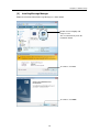
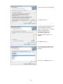
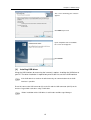
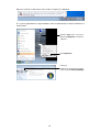
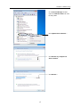
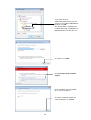
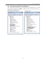
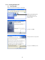
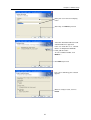
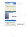
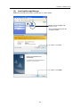
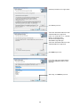
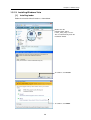
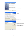
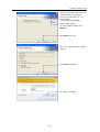
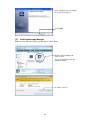
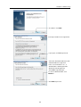
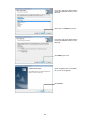
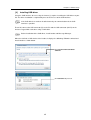
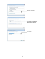
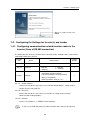
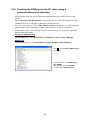
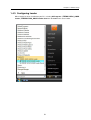
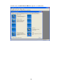
Instruction Manual
Inverter Support Software
FRENIC-HVAC/AQUA Loader
Thank you for purchasing our high-performance, vector control FRENIC-HVAC/AQUA series of inverters.
• This manual provides all the information on Fuji’s inverter support software FRENIC Loader
FRENIC-HVAC/AQUA.
Read this manual carefully for correct use of FRENIC Loader FRENIC-HVAC/AQUA
• This manual does not contain information on the inverter itself. Read the inverter user's manual, inverter
instruction manual in conjunction with this manual.
• Incorrect handling may prevent Loader from operating correctly, shorten the inverter service life, or cause
problems.
Fuji Electric Co., Ltd.
INR-SI47-1712
Copyright © 2012 Fuji Electric Co., Ltd.
All rights reserved.
No part of this publication may be reproduced or copied without prior written permission from Fuji
Electric Systems Co., Ltd.
Microsoft and Windows are registered trademarks of Microsoft Corporation in the United States. All
other products and company names mentioned in this manual are trademarks or registered trademarks
of their respective holders.
The information contained herein is subject to change without prior notice for improvement.
Preface
This manual provides all the information on Fuji’s inverter support software FRENIC-HVAC/AQUA
Loader.
Read this manual carefully for correct use of FRENIC-HVAC/AQUA Loader.
This manual does not contain information on the inverter itself. Read the inverter user's manual,
inverter instruction manual in conjunction with this manual.
Incorrect handling may prevent Loader from operating correctly, shorten the inverter service life, or
cause problems
These materials are subject to change without notice. Be sure to obtain the latest editions for use.
We plan to make the latest edition available for download from the following URL:
(URL) http://www.fe-frontrunners.eu/inverter/en/index1.htm
.
■ Safety Precautions
Read this manual thoroughly before proceeding with installation, connections (wiring), or operation.
Ensure you have sound knowledge of the device and software and have familiarized yourself with all
safety information and precautions before proceeding to operate the inverter via FRENIC Loader VG
Safety precautions are classified into the following two categories in this manual.
Failure to heed the information indicated by this symbol may result in
death or serious injury.
Failure to heed the information indicated by this symbol may result in
minor or light injury and/or substantial property damage.
Wiring and Connection of Cables
• Be sure to turn off the power to the inverters and related devices before making RS-485
connection.
Risk of electric shock if this warning is not heeded.
・When connecting an RS-485 communications cable to the RJ-45 connector on the inverter, be sure
to check the pin assignment of the device to be connected. For details, refer to Chapter 1, Section
1.2.3. " Configuring an RS-485 communications network."
An trouble could occur.
Operation
・ Resetting an alarm with a run command being ON will cause the inverter to run the motor
unexpectedly.
An accident could occur.
i
・ Loader or OS freezes or is forced to quit when Loader is operating the inverter(s) from the Test run
window, the connected inverter(s) cannot be stopped from Loader. If it happens, perform any of the
following operations to stop the inverter(s).
An accident could occur.
1) Prepare a separate emergency stop switch and use it to stop the inverter.
2) Turn off the power to the inverter.
3) Turn off the external run command at the inverter side and switch the command source from
"Via communications line" to "From inverter" by doing one of the following:
- Turn off the terminal which the LE command is assigned to.
- Set function code y99 data (Link support function) to "0 "using the keypad.
- Set function code H30 data (Link function) to "0" using the keypad.
・When operating the inverter(s) from the Test run window, never disconnect the RS-485
communications cable, USB cable, or keypad. Doing so makes it impossible to stop the inverter(s)
from Loader. It is dangerous.
An accident could occur.
ii
Contents
Preface ......................................................................................................................................................................i
Chapter 1 Before Using FRENIC-HVAC/AQUA Loader ...........................................................................................1
1.1. Overview............................................................................................................................................................1
1.1.1. Features ...................................................................................................................................................1
1.1.2. Warranty ...................................................................................................................................................1
1.2. Connecting Inverters to a PC.............................................................................................................................2
1.2.1. Connection ...............................................................................................................................................2
1.2.2. Configuring USB network .........................................................................................................................3
1.2.2.1. Example of networking .......................................................................................................................3
1.2.2.2. USB Connector on Control PCB.........................................................................................................3
1.2.3. Configuring an RS-485 communications network.....................................................................................4
1.2.3.1. Example of networking(COM port1)....................................................................................................4
1.2.3.2. Example of networking(COM port2)....................................................................................................5
1.2.3.3. Communications support devices for RS-485.....................................................................................6
[ 1 ] Converter ............................................................................................................................................. 6
[ 2 ] Cable for RJ-45 connector (COM port 1) ............................................................................................. 7
[ 3 ] Cable for RS-485 connector (COM port 2)........................................................................................... 7
[ 4 ] Branch adapter for multi-drop .............................................................................................................. 7
1.2.3.4. Noise suppression ..............................................................................................................................7
1.3. Installation .........................................................................................................................................................8
1.3.1. Installing software.....................................................................................................................................8
1.3.1.1. Installing Windows 7 ...........................................................................................................................9
[ 1 ] Installing loader.................................................................................................................................... 9
[ 2 ] Installing USB driver .......................................................................................................................... 13
[ 3 ] Installing USB driver .......................................................................................................................... 15
[ 4 ] Checking the installation of the USB driver........................................................................................ 19
1.3.1.2. Installing Windows XP ......................................................................................................................20
[ 1 ] Installing loader.................................................................................................................................. 20
[ 2 ] Installing Message Manager .............................................................................................................. 23
[ 3 ] Installing USB driver .......................................................................................................................... 25
[ 4 ] Checking the installation of the USB driver........................................................................................ 28
1.3.1.3. Installing Windows Vista ...................................................................................................................29
[ 1 ] Installing loader.................................................................................................................................. 29
[ 2 ] Installing Message Manager .............................................................................................................. 32
[ 3 ] Installing USB driver .......................................................................................................................... 35
[ 4 ] Checking the installation of the USB driver........................................................................................ 39
1.3.2. Uninstallation..........................................................................................................................................40
1.3.2.1. Uninstalling Windows 7.....................................................................................................................40
[ 1 ] Uninstalling loader ............................................................................................................................. 40
[ 2 ] Before uninstalling Message Manager............................................................................................... 41
[ 3 ] Uninstalling Message Manager.......................................................................................................... 42
1.3.2.2. Uninstalling Windows XP..................................................................................................................43
[ 1 ] Uninstalling loader ............................................................................................................................. 43
[ 2 ] Before uninstalling Message Manager............................................................................................... 44
[ 3 ] Uninstalling Message Manager.......................................................................................................... 45
iii
1.3.2.3. Uninstalling Windows Vista...............................................................................................................46
[ 1 ] Uninstalling loader ............................................................................................................................. 46
[ 2 ] Before uninstalling Message Manager............................................................................................... 47
[ 3 ] Uninstalling Message Manager.......................................................................................................... 48
1.4. Configuring the Settings for Inverter(s) and Loader.........................................................................................49
1.4.1. Configuring communication-related function codes in the inverter (Case of RS-485 connection) ..........49
1.4.2. Checking the COM port on the PC (when using a communications level converter)..............................50
1.4.3. Configuring Loader .................................................................................................................................51
1.4.4. Communication Settings.........................................................................................................................53
[ 1 ] Connection method............................................................................................................................ 53
[ 2 ] Port .................................................................................................................................................... 54
[ 3 ] Communication term.......................................................................................................................... 54
[ 4 ] Practice connection check ................................................................................................................. 55
1.4.5. Connection settings ................................................................................................................................55
[ 1 ] For connection to USB port................................................................................................................ 55
[ 2 ] For connection to RS-485 port........................................................................................................... 56
iv
Chapter 1 Before Using
Chapter 1 Before Using FRENIC-HVAC/AQUA Loader
This chapter gives an overview of the inverter support software FRENIC-HVAC/AQUA Loader and
provisions for its installation and operation.
1.1. Overview
1.1.1. Features
・ Loader enables a PC to support remote operation of inverters either individually or collectively
via the RS-485 port or the USB port on the inverters.
・ Simplified operation of Loader allows you to easily manage and set the function code data for
the inverter.
1.1.2. Warranty
Limited
Warranty
In no event will Fuji Electric Co., Ltd. be held liable for any damage (including,
but not limited to lost profit, suspension or interruption of operations, loss of
operational data or other monetary loss) whatsoever resulting from the use of
the software or malfunction of the same or from information contained in this
document.
1
1.2. Connecting Inverters to a PC
1.2.1. Connection
The table below lists the connection methods available for connecting inverters to a PC.
PC :
Inverters
1:1
On PC
On inverter
USB
USB
USB
RS-485
COM port
(RS-232C)
RS-485
USB
RS-485
COM port
(RS-232C)
RS-485
1:n
Connection
Using a USB cable
Via a USB / RS-485 converter
Via an RS-232C / RS-485 converter
Via an RS-232C / RS-485 converter
When using an RJ-45 connector, use a
branch adapter for multi-drop connection
for each of the 2nd and the subsequent
inverters.
Via an RS-232C / RS-485 converter
1) For details about the RS-232C / RS-485 converter and USB / RS-485 converter,
refer to Section 1.2.3.2. “Communications support devices for RS-485".
2)
To minimize the effects of noise, separate the signal lines from the power lines.
Refer to Section 1.2.3.2. “Noise suppression”.
3)
The inverter cannot be concurrently shared by the Loader-running PC and
other host equipment (e.g., PLC). To use Loader, therefore, be sure to
disconnect the cables of other host equipment from the RS-485 port on the
inverter.
4)
For multi-drop connection of inverters, assign different station addresses to
each of the inverters connected.
• Be sure to turn off the power to the inverters and related devices before making RS-485
connection.
Risk of electric shock if this warning is not heeded.
2
Chapter 1 Before Using
1.2.2. Configuring USB network
1.2.2.1. Example of networking
To configure a USB network connecting the inverter and a Loader-running PC, use a commercially
available USB cable (mini B connector). (See
below.)
Connection using the USB connector
For connection using the USB connector, refer to Section 1.4.4. "Communication settings"
USB cable
MAX. 5m
FRENIC Loader
Allows operation of the inverter
connected online with the PC
Figure 1.2.2.1.
USB Network Using a USB Cable (mini B)
Table 1.2.2.1.
Specifications of USB Network
Specifications
USB 1.1 compliant
Transmission speed
12M bps
Wiring length
Max. 5 m
Connector
USB mini B connector
When connecting the inverter to a PC via the USB port, be sure to connect them, one
to one. Do not use a USB hub.
1.2.2.2. USB Connector on Control PCB
The USB port (CN10*) is located on the upper right of the control printed circuit board (control PCB)
as shown below. To connect the USB cable to CN10, remove the front cover so that you can see the
control PCB.
*miniB connector, Version 2.0 compliant
Figure 1.2.2.2 Location of USB Connector
3
1.2.3. Configuring an RS-485 communications network
1.2.3.1. Example of networking(COM port1)
For connecting inverters in multi-drop connection, use the branch adapters for multi-drop
connection as shown below.
Figure 1.2.3.1.
RS-485 Multi-drop Network (Terminal Block Connections)
・Pins 1, 2, 7, and 8 on the RJ-45 connector are exclusively assigned to power supply
and grounding for keypads. When connecting other devices to the RJ-45 connector,
take care not to use those pins. Failure to do so may cause a short-circuit hazard. Use
pins 4 and 5 only.
・When selecting additional devices to prevent the damage or malfunction of the control
PCB caused by external noises or eliminate the influence of common mode noises, be
sure to refer to Section 1.2.3.3. " Communications support devices for RS-485"
・The maximum wiring length must be 500 m.
・Use cables and converters meeting the specifications for proper connection.
(Refer to [2]"Requirements for the cable (COM port 1: for RJ-45 connector)"
4
Chapter 1 Before Using
1.2.3.2. Example of networking(COM port2)
To configure an RS-485 communications network connecting inverters and a Loader-running PC,
use a Shielded twisted pair cable for long distance transmission. (See
below.)
Figure 1.2.3.2. Multi-drop Connection Diagram (Connecting to the Terminal Block)
・Use cables and converters meeting the specifications for proper connection.
(Refer to [3] "Requirements for the cable (COM port 2: for RS-485 connector)" in
Section 1.2.3.3. " Communications support devices for RS-485")
・The maximum wiring length must be 500 m.
5
1.2.3.3. Communications support devices for RS-485
This section describes the devices required for connecting the inverter to a PC having no
RS-485 interface or for connecting two or more inverters in multi-drop network.
[ 1 ] Converter
Usually PCs are not equipped with an RS-485 communications port but with an RS-232C port.
To connect inverters to a PC, therefore, you need an RS-232C–RS-485 converter or a
USB–RS-485 converter. To run the FRENIC-HVAC correctly, use a converter satisfying the
requirements given below.
Recommended converter spec
Send/receive switching:
Electric isolation:
Fail-safe:
Other requirements:
Auto-switching by monitoring of send/receive data status at the PC
(RS-232C)
Electrically isolated from the RS-485 port
Fail-safe facility*
Superior noise immunity
* The fail-safe facility refers to a feature that ensures the RS-485 receiver's output at "High"
(logical value = 0) even if the RS-485 receiver's input is opened or short-circuited or all the
RS-485 drivers are inactive.
Send/receive switching system
The RS-485 communications system of the inverter acts in half-duplex mode (2-wire) so the
converter must feature a send/receive switching circuitry. Generally, the switching system may
be either one of the following.
(1) Auto-switching by monitoring of send/receive data
(2) Switching by RS-232C control signal of RTS or DTR (hardware flow control system)
Figure 1.2.3.3. Communications Level Conversion
Recommended converter
System Sacom Sales Corporation (Japan):KS-485PTI(RS-232C - RS-485 converter)
:USB-485I RJ45-T4P(USB - RS-485 converter)
6
Chapter 1 Before Using
[ 2 ] Cable for RJ-45 connector (COM port 1)
Use a standard 10BASE-T/100BASE-TX LAN cable (US ANSI/TIA/EIA-568A category 5
compliant, straight type).
The RJ-45 connector (COM port 1) has power source pins (pins 1, 2, 7 and 8)
exclusively assigned to keypads. When connecting other devices to the RJ-45
connector, take care not to use those pins. Using them will cause a short-circuit hazard.
Use pins 4 and 5 only.
[ 3 ] Cable for RS-485 connector (COM port 2)
To ensure the reliability of connection, use twisted pair shield cables for long distance
transmission AWG 16 to 26.
Recommended LAN cable
Manufacturer: FURUKAWA Electric Co., Ltd.
AWM2789 Cable for long distance connection
Type (Product code): DC23225-2PB
[ 4 ] Branch adapter for multi-drop
An RS-485 communications network for inverters utilizes 2-wire 10BASE-T LAN cables fitted
with an RJ-45 connector at both ends. To connect those inverters to the network in multi-drop
mode, use branch adapters for multi-drop.
Recommended branch adapter
SK Koki (Japan): MS8-BA-JJJ
1.2.3.4. Noise suppression
Depending on the operating environment, instruments may malfunction due to the noise
generated by the inverter. Possible measures to prevent such malfunction are: separating the
wiring, use of shielded cable, isolating the power supply, and adding an inductance component.
Show below is an example of adding an inductance component.
Adding inductance components
To suppress or eliminate noise for keeping the network in high noise immunity level, insert
inductance components such as choke coils in series in the signal circuit, or pass the RS-485
communications cable through a ferrite core ring or wind it around by 2 or 3 turns as shown
below to keep the impedance of the signal lines high.
Ferrite core
RS-485 communications cable
RS-485
converter
Inverter
Pass the wiring through the ferrite core or
wind the ferrite core with the wiring a few times
Figure 1.2.3.4.
Adding an Inductance Component
7
1.3. Installation
1.3.1. Installing software
Before installation
Execute the following before installation.
Check items
Requirements
Windows OS
Microsoft Windows XP, Vista (32-bit), or 7 (32-bit)
Hard disk space
Free space of approx. 20MB or more
Other applications
Terminate all the applications being in execution.
[FRENIC-HVAC_AQUA Loader_1000_setup.exe] and [MsgMgr USB Setup. exe] are contained
in the CD that comes with Fuji Inverter FRENIC- HVAC/AQUA. Copy these setup files to any
folder.
To use FRENIC-HVAC/AQUA Loader, you need to install two setup files: the loader
software main program [FRENIC-HVAC_AQUA Loader_1000_setup.exe] and the
message manager [MsgMgr USB Setup.exe] that manages communications.
To install the loader software, install with an account that has sufficient authority to
install the software.
Installing software,macthing with using OS
Windows 7
See page 9
Windows XP
See page 20
Windows Vista
See page 29
8
Chapter 1 Before Using
1.3.1.1. Installing Windows 7
[ 1 ] Installing loader
Follow the wizard and install Loader as shown below.
Double-click the
FRENIC-HVAC_AQUA
Loader_1000_setup.exe icon.
The exe automatically starts the
installation wizard.
To continue, click Install.
To continue, click Yes.
9
To continue, click Next.
Carefully read the license agreement.
If you agree, click Next to proceed.
Enter your user name and company
name.
After entry, click Next to proceed.
10
Chapter 1 Before Using
Select the destination folder to install.
A default folder has appeared.
In the case of OS drive is “C”, a default
folder is “C:¥¥Fujielectric¥FRENICHVAC_AQUA Loader”.
To select a different folder, click
Browse….
Click Next to proceed.
The screen confirming your selection
appears.
Click Install to proceed.
To continue, click Yes.
11
Upon completion of the installation,
the screen at left appears.
Click Finish.
12
Chapter 1 Before Using
[ 2 ] Installing Message Manager
Follow the wizard and install Message Manager as shown below.
Double-click the MsgMgr USB
Setup.exe icon.
The exe automatically starts the
installation wizard.
To continue, click Yes.
To continue, click Next.
13
Carefully read the license agreement.
Click Yes to proceed.
Select the destination folder to install.
A default folder has appeared.
In the case of OS drive is “C”, a default
folder is “C:¥Program Files
¥Common Files¥Fuji Electric
Shared¥Message Manager”.
To select a different folder, click
Browse…
Click Next to proceed.
Select the start menu folder that the
shortcut to FRENIC Loader is to be
added to.
After entry, click Next to proceed.
14
Chapter 1 Before Using
The screen confirming your selection
appears.
Click Next to proceed.
Upon completion of the installation,
the screen at left appears.
Click Finish.
[ 3 ] Installing USB driver
Using the USB interface for accessing the inverter(s) requires installing the USB driver to
your PC. The driver installation is required only once at the first use of the USB interface.
If the USB driver has not been installed correctly, no communication via the USB
interface is possible.
First of all, connect the USB connector (A) on the PC and the USB connector (mini B) on the
inverter's keypad with each other using a USB cable.
Before installation of the USB driver, install Loader and Message Manager.
15
When the OS finds a USB device of the Loader, it displays the following.
The system-supplied driver setup wizard does not run automatically. Install the USB driver as
shown below.
From the Start menu, select and
right-click Computer to show the
submenu.
Click Properties.
Left-Click
Wait for the Control Panel Home
screen and click Device Manager.
16
Chapter 1 Before Using
On the Device Manager window,
right-click Unknown device to show
the drop-down
Click Update Driver Software….
Click Browse my computer for
driver software.
Click Browse….
17
In the folder in which
FRENIC-HVAC_AQUA Loader has been
installed, select ¥Driver¥MICREXSX
and then click OK.
The default folder is C:¥FujiElectric
¥ FRENIC-HVAC_AQUA_Loader¥Driver¥
MICREXSX when the OS drive is C.
To continue, click Next.
Click Install this driver software
anyway.
Upon completion of the installation,
the screen at left appears.
To exit the installation wizard and
return to Windows, click Close.
18
Chapter 1 Before Using
[ 4 ] Checking the installation of the USB driver
To check whether the USB driver has been installed correctly, select Windows “Start” →”Control
panel”,open”Device Manager”. If “FRENIC” is added to the sub-tree of Loader USB device, the
driver has been installed correctly.
Installation finished successfully
Installation failed
19
1.3.1.2. Installing Windows XP
[ 1 ] Installing loader
Follow the wizard and install Loader as shown below.
Double-click the RENIC-HVAC_AQUA
Loader_1000_setup.exe icon.
The exe automatically starts the
installation wizard.
To continue, click Next.
Carefully read the license agreement.
If you agree, click Next to proceed.
20
Chapter 1 Before Using
Enter your user name and company
name.
After entry, click Next to proceed.
Select the destination folder to install.
A default folder has appeared.
In the case of OS drive is “C”, a default
folder is “C:¥¥Fujielectric¥FRENICHVAC_AQUA Loader”.
To select a different folder, click
Browse….
Click Next to proceed.
The screen confirming your selection
appears.
When it is ready to restart, click Yes
Install.
21
The installation progress bar
appears.
Upon completion of the installation,
the screen at left appears.
To exit the installation wizard and
return to Windows, click Finish
When it is ready to restart, click Yes.
*If you do not restart FRENIC Loader
VG, the program cannot be normally
installed.
22
Chapter 1 Before Using
[ 2 ] Installing Message Manager
Follow the wizard and install Message Manager as shown below.
Double-click the MsgMgr USB
Setup.exe icon.
The exe automatically starts the
installation wizard.
To continue, click Yes.
To continue, click Next.
23
Carefully read the license agreement.
Click Yes to proceed.
Select the destination folder to install.
A default folder has appeared.
In the case of OS drive is “C”, a default
folder is “C:¥Program Files
¥Common Files¥Fuji Electric
Shared¥Message Manager”.
Select the destination folder to install.
A default folder has appeared.
Click Next to proceed.
Select the start menu folder that the
shortcut to FRENIC Loader is to be
added to.
After entry, click Next to proceed.
24
Chapter 1 Before Using
The screen confirming your selection
appears.
Click Next to proceed.
Upon completion of the installation,
the screen at left appears.
Click Finish.
[ 3 ] Installing USB driver
Using the USB interface for accessing the inverter(s) requires installing the USB driver to your
PC. The driver installation is required only once at the first use of the USB interface.
If the USB driver has not been installed correctly, no communication via the USB
interface is possible.
First of all, connect the USB connector (A) on the PC and the USB connector (mini B) on the
inverter's keypad with each other using a USB cable.
Before installation of the USB driver, install Loader and Message Manager.
25
When the OS finds a USB device of the Loader, it displays the following. Follow the wizard and
install Loader as shown below.
Wait for this screen to appear, select
Yes, now and every time I connect
a device, then click Next.
Select Install from a list or specific
location (Advanced), then click Next.
Select Search for the best driver in
these locations and the Include
this location in the search check
box, then click Browse….
26
Chapter 1 Before Using
In the folder in which FRENICHVAC_AQUA Loader has been
installed, select ¥Driver¥MICREXSX
and then click OK.
The default folder is C:¥Fuji Electric
¥ FRENIC- HVAC_AQUA Loader
¥Driver¥
MICREXSX when the OS drive is C.
Click Next.
Installation starts.
Upon completion of the installation,
the screen at left appears.
Click Finish
27
[ 4 ] Checking the installation of the USB driver
To check whether the USB driver has been installed correctly, select Windows” Start” →”My
computer”, select “property” with right-click, open “Hard ware”→”Device Manager” with left-click.
If “FRENIC” is added to the sub-tree of Loader USB device, the driver has been installed
correctly.
Installation finished successfully
Installation failed
28
Chapter 1 Before Using
1.3.1.3. Installing Windows Vista
[ 1 ] Installing loader
Follow the wizard and install Loader as shown below.
Double-click the
FRENIC-HVAC_AQUA
Loader_1000_setup. exe icon.
The exe automatically starts the
installation wizard.
To continue, click Install.
To continue, click Allow.
29
To continue, click Next.
Carefully read the license
agreement..
Click Next to proceed.
Enter your user name and company
name.
After entry, click Next to proceed.
30
Chapter 1 Before Using
Select the destination folder to install.
A default folder has appeared.
In the case of OS drive is “C”, a
default folder
is ”C:¥¥Fujielectric¥FRENICHVAC_AQUA Loader”
To select a different folder, click
Browse….
Click Next to proceed.
The screen confirming your selection
appears.
Click Install to proceed.
To continue, click Yes.
31
Upon completion of the installation,
the screen at left appears.
Click Finish
[ 2 ] Installing Message Manager
Follow the wizard and install Message Manager as shown below.
Double-click the MsgMgr USB
Setup.exe icon.
The exe automatically starts the
installation wizard.
To continue, click Yes.
32
Chapter 1 Before Using
To continue, click Next.
Carefully read the license agreement.
If you agree, click Yes to proceed.
Select the destination folder to install.
A default folder has appeared
In the case of OS drive is “C”, a
default folder is“C:¥Program Files
¥Common Files¥Fuji Electric
Shared¥Message Manager”
To select a different folder, click
Browse….
Click Next to proceed.
33
Select the start menu folder that the
shortcut to FRENIC Loader is to be
added to.
After entry, click Next to proceed.
Select the start menu folder that the
shortcut to FRENIC Loader is to be
added to.
Click Next to proceed.
Upon completion of the installation,
the screen at left appears.
Click Finish.
34
Chapter 1 Before Using
[ 3 ] Installing USB driver
Using the USB interface for accessing the inverter(s) requires installing the USB driver to your
PC. The driver installation is required only once at the first use of the USB interface.
If the USB driver has not been installed correctly, no communication via the USB
interface is possible.
First of all, connect the USB connector (A) on the PC and the USB connector (mini B) on the
inverter's keypad with each other using a USB cable.
Before installation of the USB driver, install Loader and Message Manager.
When the OS finds a USB device of the Loader, it displays the following. Follow the wizard and
install Loader as shown below.
Click Locate and install driver
software.
Click Continue to proceed.
35
Click Don’t search online.
Click Browse my computer for
driver software (advanced).
Click Browse…
36
Chapter 1 Before Using
In the folder in which
FRENIC-HVAC_AQUA Loader has
been installed, select
¥Driver¥MICREXSX and then click
OK.
The default folder is C:¥ Fuji Electric
¥ FRENIC-HVAC_AQUA
Loader¥Driver¥
MICREXSX when the OS drive is C
To continue, click Next.
Click Install this driver software
anyway.
37
Upon completion of the installation,
the screen at left appears.
Click Close.
This message appears when the
USB driver has been successfully
installed.
38
Chapter 1 Before Using
[ 4 ] Checking the installation of the USB driver
To check whether the USB driver has been installed correctly, open “Device Manager”. If
“FRENIC” is added to the sub-tree of Loader USB device, the driver has been installed correctly.
Installation finished successfully
Installation failed
39
1.3.2. Uninstallation
1.3.2.1. Uninstalling Windows 7
[ 1 ] Uninstalling loader
From Windows “Start”, select All Programs [FRENIC-HVAC_AQUA Loader |
[FRENIC-HVAC_AQUA Loader Uninstall
Click Yes
The confirmation screen at left
appears.
Click Yes.
40
Chapter 1 Before Using
The uninstallation progress bar
appears.
To abort the uninstallation, click
Cancel.
In the above procedure, perform the uninstallation.
[ 2 ] Before uninstalling Message Manager
Before uninstalling Message Manager, be sure to quit both Loader and Message Manager.
Quitting Message Manager
Message Manager is software that manages communication between the PC and
inverters. To make sure that Message Manager has quitted, check that no Message
Manager icon is displayed in the task tray. If the icon is displayed, right-click it to quit
Message Manager. If doing so cannot quit it, shut down or log off Windows.
Once you uninstall Loader when Message Manager is running, a new version of Loader
installed after that cannot run properly, that is, it may no longer be able to recognize
inverters. If this happens, first delete the folder (including its contents) named Fuji
Electric Shared in the file path as shown below, and then reinstall Loader.
C:¥Program Files¥Common Files¥Fuji Electric Shared
(In the file path shown above, "C" represents the drive letter of the partition or hard disk
where Windows is installed. If Windows is installed on a different drive in your system,
replace "C" with the letter corresponding to that drive.)
Quitting Message Manager
Click this to display the hidden icons as shown below.
Right-click this icon to display Exit MessageManager, then click it. The confirmation
window appears. Click Yes to quit Message Manager
41
[ 3 ] Uninstalling Message Manager
From the Start menu, select All Programs | Message Manager | Message Manager Uninstall.
To continue, click Yes.
The confirmation screen at left
appears.
To continue the uninstallation
procedure, click Yes.
In the above procedure, perform the uninstallation.
42
Chapter 1 Before Using
When it is ready to restart, click
Finish.
1.3.2.2. Uninstalling Windows XP
[ 1 ] Uninstalling loader
From the Start menu, select All Programs | FRENIC-HVAC_AQUA Loader |
FRENIC-HVAC_AQUA Loader Uninstall.
The uninstallation confirmation
screen appears as shown left.
To proceed and uninstall Loader,
click Yes.
43
The uninstallation progress bar
appears.
To abort the uninstallation, click
Cancel.
In the above procedure, perform the uninstallation.
[2]
Before uninstalling Message Manager
Before uninstalling Message Manager, be sure to quit both Loader and Message Manager.
Quitting Message Manager
Message Manager is software that manages communication between the PC and
inverters. To make sure that Message Manager has quitted, check that no Message
Manager icon is displayed in the task tray. If the icon is displayed, right-click it to quit
Message Manager. If doing so cannot quit it, shut down or log off Windows.
Once you uninstall Loader when Message Manager is running, a new version of Loader
installed after that cannot run properly, that is, it may no longer be able to recognize
inverters. If this happens, first delete the folder (including its contents) named Fuji
Electric Shared in the file path as shown below, and then reinstall Loader.
C:¥Program Files¥Common Files¥Fuji Electric Shared
(In the file path shown above, "C" represents the drive letter of the partition or hard disk
where Windows is installed. If Windows is installed on a different drive in your system,
replace "C" with the letter corresponding to that drive.)
Quitting Message Manager
Right-click the Message Manager icon to display Exit MessageManager, then click it.
The confirmation window appears. Click Yes to quit Message Manager.
44
Chapter 1 Before Using
[3]
Uninstalling Message Manager
From the Start menu, select All Programs | Message Manager | Message Manager Uninstall.
The uninstallation confirmation
screen appears as shown left.
To proceed and uninstall Loader,
click Yes.
In the above procedure, perform the uninstallation.
When it is ready to restart, click
Finish.
45
1.3.2.3. Uninstalling Windows Vista
[ 1 ] Uninstalling loader
From the Start menu, select All Programs | FRENIC-HVAC_AQUA Loader |
FRENIC-HVAC_AQUA Loader Uninstall.
The confirmation screen at left
appears.
Click Yes.
The confirmation screen at left
appears.
Click Yes.
46
Chapter 1 Before Using
The uninstallation progress bar
appears.
To abort the uninstallation, click
Cancel.
In the above procedure, perform the uninstallation.
[2]
Before uninstalling Message Manager
Before uninstalling Message Manager, be sure to quit both Loader and Message Manager.
Quitting Message Manager
Message Manager is software that manages communication between the PC and
inverters. To make sure that Message Manager has quitted, check that no Message
Manager icon is displayed in the task tray. If the icon is displayed, right-click it to quit
Message Manager. If doing so cannot quit it, shut down or log off Windows.
Once you uninstall Loader when Message Manager is running, a new version of Loader
installed after that cannot run properly, that is, it may no longer be able to recognize
inverters. If this happens, first delete the folder (including its contents) named Fuji
Electric Shared in the file path as shown below, and then reinstall Loader.
C:¥Program Files¥Common Files¥Fuji Electric Shared
(In the file path shown above, "C" represents the drive letter of the partition or hard disk
where Windows is installed. If Windows is installed on a different drive in your system,
replace "C" with the letter corresponding to that drive.)
Quitting Message Manager
Right-click the Message Manager icon to display Exit MessageManager, then click it.
The confirmation window appears. Click Yes to quit Message Manager.
47
[3]
Uninstalling Message Manager
From the Start menu, select All Programs | Message Manager | Message Manager Uninstall.
Click Yes.
The confirmation screen at left
appears.
To continue the uninstallation
procedure, click Yes.
In the above procedure, perform the uninstallation.
48
Chapter 1 Before Using
When it is ready to restart, click
Finish.
1.4. Configuring the Settings for Inverter(s) and Loader
1.4.1. Configuring communication-related function codes in the
inverter (Case of RS-485 connection)
The table below lists inverter's function codes related to Loader. Configure those codes before
connecting Loader to the inverter
Function
code
Name
Setting range
y01/y11
Station address
1~255
y04/y14
Baud rate
0:2400 bps
2:9600 bps
4:38400 bps
y 10/y20
Protocol
Factory
default
1
1:4800 bps
3:19200 bps
0:Modbus RTU protocol
1:SX protocol (Loader protocol)
2:Fuji general-purpose inverter protocol
3:Metasys N2 protocol
4
1
5:BACnet protocol(AQUA/y20 only)
y01/y11:Station address
Set the H31 data to the same value as the RS-485 Station address. setting made in
Loader's Device connection list.
y04/y14:Baud rate
Set the H34 data to the same value as the baud rate setting made in Loader's
Communication Setting window.)
y10/y20:Protocol
Set the y10/y20 data to "1" (FRENIC Loader protocol).
In the case of USB connection, the above function code setting is not required.
49
1.4.2. Checking the COM port on the PC (when using a
communications level converter)
Loader running on the PC uses the RS-232C communications port (COM) to interface with
inverters.
When an RS-232C / RS-485 converter is connected to the PC, check what COM port number
(COM#) on the PC is assigned to the RS-232C / RS-485 converter.
To use the USB interface, select a USB / RS-485 converter that functions as a virtual RS-232C
communications port (COM). When a USB / RS-485 converter is connected, Windows
automatically assigns a free COM port on the PC to the converter. To check the assignment,
follow the procedure below.
Windows 7 / Windows Vista
From the Start menu, select Control Panel | Hardware and Sound | Device Manager.
Windows XP
From the Start menu, select Control Panel | System | Hardware | Device Manager.
Click + preceding Ports (COM & LPT) to
show details.
Check the number "n" in USB Serial
Port (COMn).
This example shows that COM3 is
assigned to the USB Serial Port.
50
Chapter 1 Before Using
1.4.3. Configuring Loader
When Loader has been installed on your PC, selecting All Programs | FRENIC-HVAC_AQUA
Loader | FRENIC-HVAC_AQUA Loader Start from the Start menu starts Loader.
51
If Loader starts, the Quick Access Menu first appears as shown below.
52
Chapter 1 Before Using
1.4.4. Communication Settings
Click [COM.Setting.] icon in the left row in Simple Menu to display the screen which sets
the methods to connect the loader, targets to be connected and communication
conditions.
Enter the data by referring to the following descriptions. Alternatively, by
selecting Setup | Communication Settings from Main Menu, you can display the
communication setting screen without using Simple Menu.
[ 1 ] Connection Methods
Select the method to connect the loader.
Connect Loader Directly to Inverter
Select this method when connecting your PC to the inverter directly, not via MICREX-SX
Controller.
(You can select one of the two communication types: RS485 or USB.)
53
[ 2 ] Port
You can do settings on communications. (Since the original setting match with COM setting of
inverter,communication can fix without any change in the original condition.)
RS-485
Select this method when connecting your PC to the inverter via RS-485.
・ Port setting
Select the communication port of the PC to which the RS-232C / RS-485 converter is
connected.
・ Baud rate
Set the transmission rate.
inverter.
You must select the transmission rate same as the one for the
・ Flow control
Since the recommended converter manages the flow control by automatic switching
through transmission data monitoring, you do not have to change this setting. The
flow control is a method that uses RS-232C control signals to control RS-485
transmission/reception switching.
・ Data length:
length : No setting
・ Parity:
Parity : No setting
・ Stop bit:
: No setting
USB
Select this method when connecting your PC to the inverter directly via USB.
Communication board
No setting “Communicate via MICREX-SX”
・ Type:
: No setting
・ Parameter: No setting
・ Port number: No setting
[ 3 ] Communication Conditions
Do the settings on the communication retry.
・ Retry count
This sets how many times communication allows retry in case of failure. As the retry count
increases, the possibility to succeed communications may increase. However, it will take
time until the error dialog appears. The count of one or so is recommended.
・ Timeout
If no response is received from the inverter within the time limit set here, the communication
error dialog will open.
A shorter timeout setting allows sooner display of the error dialog.
However, an extremely short timeout may cause a communication error even during normal
operation, for example, when taking long time to handle the inverter rather than the
communication errors.
54
Chapter 1 Before Using
[ 4 ] Perform Connection Check
Connection Check is a function to always monitor the communication status between your PC
and the inverter that is registered through the connection settings.
By clicking the check box to
the left of [Perform Connection Check] and checking the box, the PC will automatically check the
status of connection with the inverter and displays the communication status on the status bar.
If one of the previously registered inverters disables to communicate due to disconnection or
other problem, the response performance will become very slow.
Be sure to remove the
disabled inverter from the connection settings.
1.4.5. Connection settings
Click COM setting | Connection Setting to display the Connection Settings screen.
[ 1 ] For connection to USB port
When "USB: Data in inverter" is selected
Only a single line appears as shown below. After making sure that the equipment name and
RS-485 num. (station address) are correct, click the Browse button to monitor the current
communications link status.
Selection of inverters to be
monitored
To make an inverter enable to
be monitored, put a check
mark () in the box located at
the left end column of the list.
Browse
Clicking this button checks
whether a link between
Loader and the inverter is
established. The result
appears in the Status column.
Status column
- Unknown
: The communications status has been unknown.
- Connecting
: The communications link has been established.
- Disconnected
: The communications link has not yet been established.
Advance…
Clicking the row to be modified and clicking
this Advance button calls up the Advanced
dialog shown at the right.
Clicking the OK button returns to the Device
connection list window.
After completion of data entry, check the settings again and click OK to exit the device
connection operation.
55
[ 2 ] For connection to RS-485 port
When "RS-485: Data in inverter" is selected
The Device connection list window shows the inverters available for RS-485 communication.
Double-clicking (or use the Advance… button) the row where the inverter to be modified or
added is listed calls up Advanced dialog shown below.
Selection of inverters to be
monitored
To make an inverter enable to
be monitored, put a check
mark () in the box located at
the left end column of the list.
Delete
Clicking the row to be deleted and clicking this Delete button deletes the inverter listed in that
row. Use this for the inverter(s) that has been disconnected from Loader.
Browse
Clicking this button checks whether a link between Loader and the inverter(s) (marked with )
is established. The result appears in the Status column.
Status column
- Unknown
: The communications status has been unknown.
- Connecting
: The communications link has been established.
- Disconnected
: The communications link has not yet been established.
Advance…
Clicking the row to be modified or added and
clicking this Advance button calls up the
Advanced dialog shown at the right.
Fill in the Equipment name and RS-485
address (station address) boxes in the
dialog and click OK. To cancel your entry or
selection, click Cancel.
Clicking the OK button returns to the Device
connection list window.
After completion of data entry, check the settings again and click OK to exit the device
connection operation.
56
Inverter Support Software
FRENICFRENIC-HVAC/AQUA Loader
Instruction Manual
First Edition, October 2012
Fuji Electric Co., Ltd.
The purpose of this instruction manual is to provide accurate information in handling, setting up and operating of
the FRENIC-HVAC/AQUA series of inverters. Please feel free to send your comments regarding any errors or
omissions you may have found, or any suggestions you may have for generally improving the manual.
In no event will Fuji Electric Co., Ltd. be liable for any direct or indirect damages resulting from the application of
the information in this manual.
Fuji Electric Co., Ltd.
Gate City Ohsaki, East Tower, 11-2, Osaki 1-chome, Shinagawa-ku, Tokyo, 141-0032, Japan
Phone: +81 3 5435 7058
URL
Fax: +81 3 5435 7420
http://www.fujielectric.com/
2012-10