1
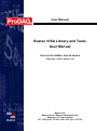
User Manual
Bustec VISA Library and Tools
User Manual
PUBLICATION NUMBER: 8200-XX-UM-0020
Copyright, © 2013, Bustec Ltd.
Bustec Ltd.
Bustec House, Shannon Business Park
Shannon, Co. Clare, Ireland
Tel: +353 (0) 61 707100, FAX: +353 (0) 61 707106
PROPRIETARY NOTICE
This document and the technical data herein disclosed, are proprietary to Bustec
Ltd., and shall not, without express written permission of Bustec Ltd, be used, in
whole or in part to solicit quotations from a competitive source or used for
manufacture by anyone other than Bustec Ltd. The information herein has been
developed at private expense, and may only be used for operation and maintenance
reference purposes or for purposes of engineering evaluation and incorporation
into technical specifications and other documents, which specify procurement of
products from Bustec Ltd.. This document is subject to change without further
notification. Bustec Ltd. Reserve the right to change both the hardware and
software described herein.
Bustec VISA User Manual
8200-XX-UM
Table of Contents
1.
INTRODUCTION .......................................................................................................... 7
1.1
1.2
2.
Related Documentation ......................................................................................... 8
Terms and Acronyms ............................................................................................ 9
THE VISA LIBRARY .................................................................................................. 11
2.1
Shared Components ............................................................................................ 11
2.1.1 VXIplug&play Infrastructure ............................................................................. 11
2.1.2 The VISA Router ............................................................................................. 14
2.2
Bustec VISA Implementation ............................................................................... 17
2.2.1 VISA Implementation for 32-bit Systems ......................................................... 17
2.2.2 VISA Implementation for 64-bit Systems ......................................................... 18
2.2.3 VISA Implementation for non-Windows Platforms ........................................... 18
2.2.4 VISA Extensions .............................................................................................. 19
2.3
Installing the Bustec VISA Library ....................................................................... 19
2.4
Installing drivers for Slot-0 modules..................................................................... 21
3.
TOOLS AND UTILITIES ............................................................................................. 22
3.1
Bustec Agent ....................................................................................................... 22
3.2
Configuration Utility ............................................................................................. 22
3.2.1 Handling Interfaces.......................................................................................... 22
3.2.2 VXIbus Resource Manager Configuration ....................................................... 27
3.2.3 Network Instruments........................................................................................ 28
3.3
VXIbus Resource Manager ................................................................................. 31
3.3.1 GUI Application ............................................................................................... 31
3.3.2 Console Application ......................................................................................... 33
3.4
VISA Assistant ..................................................................................................... 33
3.4.1 Template Operations ....................................................................................... 35
3.4.2 Basic I/O Operations ....................................................................................... 36
3.4.3 Memory I/O Operations ................................................................................... 36
3.4.4 Shared Memory Operations ............................................................................ 37
3.4.5 VXI Specific Operations................................................................................... 38
3.5
VISA Monitor ....................................................................................................... 39
3.5.1 Main Window ................................................................................................... 39
3.5.2 Display Settings ............................................................................................... 41
3.5.3 Message Filtering ............................................................................................ 42
3.5.4 Remote VISA Mode ......................................................................................... 43
3.5.5 Redirect Output ............................................................................................... 44
3.5.6 Offline Mode .................................................................................................... 44
3.6
Conflict Manager ................................................................................................. 45
3.6.1 Selecting the Preferred VISA ........................................................................... 45
3.6.2 Assigning Interfaces ........................................................................................ 46
3.6.3 32-bit VISA ...................................................................................................... 47
4.
PROGRAMMING EXAMPLES ................................................................................... 50
4.1
Connecting to a Device ....................................................................................... 50
4.2
Programming Register-based Devices ................................................................ 51
4.2.1 Accessing Registers ........................................................................................ 51
Copyright, © 2013 Bustec Ltd.
Page 3 of 63
8200-XX-UM
Bustec VISA User Manual
4.2.2 Moving Blocks of Data ..................................................................................... 54
4.3
Programming Message-based Devices ............................................................... 57
4.3.1 Writing and Reading Messages ....................................................................... 57
4.4
Optimizing Programs ........................................................................................... 58
4.5
Using VXIbus and Front Panel Trigger Lines....................................................... 59
4.5.1 Using VXIbus Trigger Lines ............................................................................. 59
4.5.2 Using Front-Panel Trigger Lines ...................................................................... 60
Page 4 of 63
Copyright, © 2010 Bustec Production Ltd.
Bustec VISA User Manual
8200-XX-UM
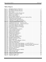
Table of Figures
Figure 1 - VXIplug&play System Architecture ...................................................................... 7
Figure 2 - 32-bit Systems Directory Structure .................................................................... 11
Figure 3 - 64-bit Systems Directory Structure .................................................................... 12
Figure 4 – Bustec Agent .................................................................................................... 22
Figure 5 – Hot plug from ProDAQ 3030 detected .............................................................. 22
Figure 6 - VISA Library Configuration Utility ...................................................................... 23
Figure 7 - Adding a new Interface ...................................................................................... 24
Figure 8 - List of configured interfaces ............................................................................... 24
Figure 9 - Add New Interface Dialog – opening the mapping dialog. ................................. 25
Figure 10 - Add Network Interface dialog........................................................................... 26
Figure 11 - Updated Available Interfaces List .................................................................... 26
Figure 12 – Updated list of configured interfaces ............................................................... 27
Figure 13 - VXIbus Resource Manager Configuration ....................................................... 27
Figure 14 – Configuring Network Instruments.................................................................... 28
Figure 15 - Add Network Instrument – using host name .................................................... 29
Figure 16 - Add Network Instrument – custom device name ............................................. 29
Figure 17 - List of known Network Instruments .................................................................. 30
Figure 18 - Searching for Network Instruments ................................................................. 30
Figure 19 - Running the VXI Resource Manager ............................................................... 31
Figure 20 - The VISA Assistant .......................................................................................... 34
Figure 21 - VISA Assistant Session Window ..................................................................... 34
Figure 22 - Using a template operation .............................................................................. 35
Figure 23 - Using basic I/O operation ................................................................................ 36
Figure 24 - Memory I/O Operations ................................................................................... 37
Figure 25 - Shared Memory Operations............................................................................. 38
Figure 26 - VXI Specific Operations ................................................................................... 39
Figure 27 – Bustec VISA Monitor ....................................................................................... 40
Figure 28 - VISA Monitor Display Settings ......................................................................... 41
Figure 29 - Message Filtering Dialog ................................................................................. 42
Figure 30 - Remote VISA Access Dialog ........................................................................... 43
Figure 31 - Redirecting Output ........................................................................................... 44
Figure 32 - Bustec VISA Conflict Manager Interface ......................................................... 45
Figure 33 - Selecting a preferred VISA .............................................................................. 46
Figure 34 - Selecting a VISA Library .................................................................................. 46
Figure 35 – Bustec 32-bit VISA Conflict Manager – no visa32.dll found ............................ 47
Figure 36 – Bustec 32-bit VISA Conflict Manager, third party primary VISA detected ....... 48
Figure 37 – Bustec 32-bit VISA Conflict Manager – renaming VISA library ....................... 48
Figure 38 – Bustec 32-bit VISA Conflict Manager .............................................................. 48
Figure 39 - Opening a VISA Session ................................................................................. 50
Figure 40 - Memory-based I/O ........................................................................................... 52
Figure 41 - Register I/O using memory mapping ............................................................... 53
Figure 42 - Moving a Block of Data .................................................................................... 54
Figure 43 - VXIbus transfer types ...................................................................................... 55
Figure 44 - Performing VXIbus Block Transfers ................................................................. 56
Figure 45 - Reading the Device Identification .................................................................... 57
Figure 46 - Sending a Trigger Pulse .................................................................................. 59
Figure 47 - Mapping Trigger Lines ..................................................................................... 61
Copyright, © 2013 Bustec Ltd.
Page 5 of 63
8200-XX-UM
Bustec VISA User Manual
This page was intentionally left blank.
Page 6 of 63
Copyright, © 2010 Bustec Production Ltd.
Bustec VISA User Manual
8200-XX-UM
1. Introduction
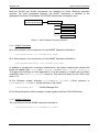
In 1993, a group of leading VXI technology vendors formed the VXIplug&play Systems
Alliance, which defined complete system frameworks that gave end-users “plug & play”
interoperability at both the hardware and system software level. The system frameworks
ensure that a VXIplug&play system can be assembled without concern for the compatibility
or interoperability of the selected components. Each VXIplug&play system component
conforms to one or more system frameworks. The system designers select the framework
that meet their needs and then select VXIplug&play components that conform to the
selected framework.
The major component of each framework is the VISA (Virtual Instrument Software
Architecture) library, which provides a standardized I/O interface to/from the instruments
for both instruments drivers and application programs. While designed mainly to handle
VXIbus systems, its open architecture from the start supported other hardware interfaces
like serial ports or GPIB. Nowadays it supports a variety of interfaces and allows the
design of multivendor, hybrid test systems using common software architecture.
Application
Instrument Driver(s)
VISA
VXIbus
RS232
GPIB
TCPIP
USB
PXI
Figure 1 - VXIplug&play System Architecture
This manual describes the implementation, configuration and use of the Bustec
implementation of the VISA library and tools.
Copyright, © 2013 Bustec Ltd.
Page 7 of 63
8200-XX-UM
1.1
Bustec VISA User Manual
Related Documentation
In 1997 the Interchangeable Virtual Instruments (IVI) Foundation was formed, which
defined a set of interchangeable instrument driver models built on VXIplug&play-compliant
frameworks. The VXIplug&play Systems Alliance merged with the IVI Foundation in 2003,
which now maintains all specifications related to the standard.
VPP-1:
VPP-2:
VPP-3.1:
VPP-3.2:
VPP-3.3:
VPP-3.4:
VPP-4.3:
VPP-4.3.2:
VPP-4.3.3:
VPP-4.3.4:
VPP-4.3.5:
VPP-6:
VPP-7:
VPP-9:
Charter Document
System Frameworks Specification
Instrument Drivers Architecture and Design Specification
Instrument Driver Functional Body Specification
Instrument Driver Interactive Developer Interface Specification
Instrument Driver Programmatic Developer Interface Specification
The VISA Library
VISA Implementation Specification for Textual Languages
VISA Implementation Specification for the G Language
VISA Implementation Specification for COM
VISA Shared Components
Installation and Packaging Specification
Soft Front Panel Specification
Instrument Vendor Abbreviations
These standards are available on the IVI Foundation web site (www.ivifoundation.org) for
download.
Other documents:
ANSI/IEEE Standard 488.1-1987, IEEE Standard Digital Interface for
Programmable Instrumentation
ANSI/IEEE Standard 488.2-1992, IEEE Standard Codes, Formats, Protocols, and
Common Commands
ANSI/IEEE Standard 1014-1987, IEEE Standard for a Versatile Backplane Bus:
VMEbus
VXI-1, VXIbus System Specification, Revision 4.0, VXIbus Consortium
VXI-11, TCP/IP Instrument Protocol, VXIbus Consortium
Page 8 of 63
Copyright, © 2010 Bustec Production Ltd.
Bustec VISA User Manual
1.2
8200-XX-UM
Terms and Acronyms
The following are some commonly used terms within this document:
Address
A string (or other language construct) that uniquely locates
and identifies a resource. VISA defines an ASCII-based
grammar that associates strings with particular physical
devices or interfaces and VISA resources.
ADE
Application Development Environment
API
Application Programmers Interface. The direct interface that
an end user sees when creating an application. The VISA
API consists of the sum of all of the operations, attributes,
and events of each of the VISA Resource Classes.
Attribute
A value within a resource that reflects a characteristic of the
operational state of a resource.
Device
An entity that receives commands from a controller. A device
can be an instrument, a computer (acting in a non-controller
role), or a peripheral (such as a plotter or printer). In VISA,
the concept of a device is generally the logical association of
several VISA resources.
DLL
Dynamic Link Library
Instrument
A device that accepts some form of stimulus to perform a
designated task, test, or measurement function. Two common
forms of stimuli are message passing and register reads and
writes. Other forms include triggering or varying forms of
asynchronous control.
Instrument Driver
Library of functions for controlling a specific instrument.
Interface
A generic term that applies to the connection between
devices and controllers. It includes the communication media
and the device/controller hardware necessary for crosscommunication.
Mapping
An operation that returns a reference to a specified section of
an address space and makes the specified range of
addresses accessible to the requester. This function is
independent of memory allocation.
mDNS
Multicast DNS
Operation
An action defined by a resource that can be performed on a
resource.
Process
An operating system component that shares a system’s
resources. A multiprocess system is a computer system that
allows multiple programs to execute simultaneously, each in
a separate process environment.
Copyright, © 2013 Bustec Ltd.
Page 9 of 63
8200-XX-UM
Bustec VISA User Manual
Register
An address location that either contains a value that is a
function of the state of hardware or can be written into to
cause hardware to perform a particular action or to enter a
particular state. In other words, an address location that
controls and/or monitors hardware.
Resource Class
The definition for how to create a particular resource. In
general, this is synonymous with the connotation of the word
class in object-oriented architectures. For VISA Instrument
Control Resource Classes, this refers to the definition for how
to create a resource that controls a particular capability of a
device.
Resource or
Resource Instance
In general, this term is synonymous with the connotation of
the word object in object-oriented architectures. For VISA,
resource more specifically refers to a particular implementtation (or instance in object-oriented terms) of a Resource
Class. In VISA, every defined software module is a resource.
Session
The same as Communication Channel. A communication
path between a software element and a resource. Every
communication channel in VISA is unique.
VISA
Virtual Instrument Software Architecture. This is the general
name given to this document and its associated architecture.
The architecture consists of two main VISA components: the
VISA Resource Manager and the VISA Instrument Control
Resources.
VISA COM
VISA for COM. VISA COM is an architecture that provides
VISA functionality via a COM API.
WOW64
Windows On Windows 64, a Microsoft technology for allowing
the execution of 32-bit native code programs on 64-bit
operating systems.
Page 10 of 63
Copyright, © 2010 Bustec Production Ltd.
Bustec VISA User Manual
8200-XX-UM
2. The VISA Library
2.1
Shared Components
Starting with release version 4.2 of the VISA library, the VISA Shared Components, a
common set of VISA components for developing multivendor software programs, are
installed with each vendor-specific VISA implementation.
The components are “shared” because multiple VISA and VISA COM vendor-specific
implementations must share a single copy of each component. Because there may only be
a single copy of the component per PC, and the behaviour of each component is precisely
described, the IVI Foundation supplies a standard implementation of each of them; in fact,
the IVI Foundation implementation of each shared component must be used wherever the
component is called for.
The VISA Shared Components include the VXIplug&play infrastructure, VISA COM
components, and VISA Plug-In Architecture components. The VXIplug&play infrastructure
includes the framework directory structure, registry entries, and environment variables.
The VISA Plug-In Architecture components include shared files that allow multiple vendorspecific VISA libraries to be installed on a single PC. In the past, the standard did not
directly support this, as each vendor-specific VISA library had to install a file named
visa32.dll in the system directory.
The VISA COM components include shared VISA COM functionality, including the VISA
COM type library, the associated PIA, the Global Resource Manager, and Basic Formatted
IO.
2.1.1 VXIplug&play Infrastructure
The VXIplug&play infrastructure includes the directories, registry keys and values, and
environment variables for each installed VXIplug&play framework.
The WinNT framework is installed on 32-bit Windows operating systems.
VXIPNPPATH
(32-bit root directory)
KBASE
(Knowledge Base Files)
WINNT
GWINNT
Bin
Bin
include
Instrument driver
lib
lib_x64
Instrument driver
Figure 2 - 32-bit Systems Directory Structure
Copyright, © 2013 Bustec Ltd.
Page 11 of 63
8200-XX-UM
Bustec VISA User Manual
Both the WinNT and Win64 frameworks are installed on 64-bit Windows operation
systems. On 64-bit operations systems, the WinNT framework is installed to the
appropriate Windows On Windows 64 (WOW64) directories and registry keys.
VXIPNPPATH
(64-bit root directory)
WIN64
Bin
include
lib_x64
Instrument driver
Figure 3 - 64-bit Systems Directory Structure
2.1.1.1 WINNT Framework
On a 32-bit system, the root directory for the WINNT framework defaults to
$(ProgramFiles)\IVI Foundation\VISA.
On a 64-bit system, the root directory for the WINNT framework defaults to
$(ProgramFiles(x86))\IVI Foundation\VISA.
In addition to creating the necessary infrastructure, the shared components installer will
install the header files visa.h and visatype.h in the WINNT\include directory.
To support the building of 64-bit application on 32-bit systems, it installs the link library
visa64.lib in the WINNT\lib_x64\msc directory. This is the link library for the VISA router
(see 2.1.2)
In the Windows system directory $(SYSTEMROOT)\system32 (32-bit systems) or
$(SYSTEMROOT)\SysWOW64 (64-bit systems) it will install:
visaConfMgr.dll
Conflict Manager DLL
On 32-bit systems the conflict manager is used together with the VISA COM router.
2.1.1.2 WIN64 Framework
The root directory for the WIN64 framework defaults to
$(ProgramFiles)\IVI Foundation\VISA.
Page 12 of 63
Copyright, © 2010 Bustec Production Ltd.
Bustec VISA User Manual
8200-XX-UM
The shared components installer will create the infrastructure both the WINNT and the
WIN64 framework. In the WIN64 framework directory structure, it will install the files
WIN64\include\visa.h
WIN64\include\visatype.h
WIN64\lib_x64\msc\visa32.lib
WIN64\lib_x64\msc\visa64.lib
In the Windows system directory $(SYSTEMROOT)\system32 it will install:
visa32.dll
visa64.dll
visaConfMgr.dll
visaUtilities.dll
64-bit Forwarding VISA DLL
64-bit VISA Router DLL
Conflict Manager DLL
Misc. VISA utility functions
The 64-bit forwarding VISA DLL visa32.dll provides compatibility with earlier version of
the WIN64 framework. It should no longer be used by application and system designers.
All applications must be linked to the VISA Router DLL visa64.dll via the link library
visa64.lib. The VISA Router and Conflict Manager are described in the next chapters.
Copyright, © 2013 Bustec Ltd.
Page 13 of 63
8200-XX-UM
Bustec VISA User Manual
2.1.2 The VISA Router
Prior to the release version 4.2 of the VISA standard, it was required of each vendor who
implemented the VISA library, to install it in the same location and under the same name.
For a user to use communication (hardware) interfaces from different vendors on the same
machine was impossible.
visa32.dll
Vendor #1
HW Interface A
Conflict
Application / Instrument Drivers
visa32.dll
Vendor #2
HW Interface B
The only solution was the implementation of special driver interfaces, which could
communicate with the hardware specific driver of the other manufacturer.
Application / Instrument Drivers
visa32.dll
visa32.dll
Vendor #1
Vendor #2
Driver
HW Driver
HW Interface A
HW Interface B
This multiplied the amount of work - each vendor supporting such a scheme would need
not only to test the proper function of his own drivers, but also of all drivers from other
vendors he supports.
Page 14 of 63
Copyright, © 2010 Bustec Production Ltd.
Bustec VISA User Manual
8200-XX-UM
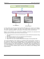
Another possibility is the so called side-by-side installation of multiple VISAs. In this case
one VISA would install in the way required by the standard (“Primary” VISA), and all other
VISAs would install using a vendor-specific name (“Secondary” VISAs). The Bustec VISA
library supports this type of installation for 32-bit systems.
Application / Instrument Drivers
run-time
dynamic
linking
visa32.dll
buvisa32.dll
Vendor #1
Bustec
HW Interface A
HW Interface B
In this case the VISA library using the vendor-specific name must be used using run-time
dynamic linking and function name resolving. Precompiled instrument drivers cannot be
used with the secondary VISAs, they need to be recompiled using the created interface.
Starting with release version 4.2 on 64-bit systems now all vendor specific VISA libraries
will be installed as secondary VISAs. The VISA router implemented by the IVI Foundation
and distributed with the VISA Shared Components implements entry points defined by the
VISA API, but only so that it can call the corresponding entry points in vendor-specific
implementations of VISA. VISA users call the VISA API through the VISA Router. The
VISA Router routes calls to the appropriate vendor-specific VISA, and also handles
callbacks from the vendor-specific VISA to the calling program. The VISA object handles
used by the Visa Router are unique and different from the VISA object handles returned
from the underlying vendor-specific VISA libraries. The VISA Router takes care of mapping
its object handles to the handles used by each of the underlying VISA libraries.
Once a session is opened in the VISA Router, most of the VISA entry points simply map
the VISA session handle passed into the call to the handle of the underlying vendorspecific VISA, call the underlying VISA, and return the results. There are a few entry
points, however, where the process is more complicated because the router needs either
to call more than one underlying VISA or determine which underlying VISA to call.
Copyright, © 2013 Bustec Ltd.
Page 15 of 63
8200-XX-UM
Bustec VISA User Manual
Application / Instrument Drivers
VISA Router (visa64.dll)
run-time dynamic linking
xxvisa64.dll
buvisa64.dll
Vendor #1
Bustec
HW Interface A
HW Interface B
In cases where more than one vendor-specific VISA library can connect to an interface,
the conflict resolution manager, also part of the VISA shared components, provides
information regarding available vendor-specific VISA libraries and user preferences.
Based on this information, the router tries to establish a connection to a resource in the
following order and returns with the first one that succeeds:
1. The VISA that the user chose to handle devices on the interface the resource string
specifies.
2. The VISA that was last used to successfully open this resource.
3. The “preferred” VISA, if one was specified.
4. Each VISA in the list of installed VISA libraries that has not already been tried
The manual assignment of an interface to a particular VISA implementation, selection of
the “preferred” VISA and the enabling/disabling of VISA implementations are done via
interfaces to the conflict resolution manager, which are implemented in the vendor specific
tools accompanying most VISA implementations. The Bustec VISA Conflict Manager (see
3.6: Conflict Manager) is such an interface to the conflict resolution manager so that the
user can choose how available system resources are handled by the underlying VISA
implementations.
Page 16 of 63
Copyright, © 2010 Bustec Production Ltd.
Bustec VISA User Manual
2.2
8200-XX-UM
Bustec VISA Implementation
Bustec’s implementation of VISA complies with the VXIplug&play standard VPP4.3
revision 5.0. For its application programmer’s interface and related standards for its
installation, tools, extensions and interoperability with other vendor-specific VISA
implementations, see section 1.1.
The VISA library provided by Bustec Ltd allows communication to the ProDAQ Slot-0
modules and the VXI instruments installed together with them in the same mainframe. It
also allows to access devices through standard interfaces like TCPIP and ASRL.
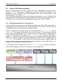
2.2.1 VISA Implementation for 32-bit Systems
Coming forward the customers’ needs, Bustec provides own 32-bit VISA router library. It
works exactly as the 64-bit VISA router provided by the IVI Foundation. However, due to
compatibility issues, the setup process is slightly different.
Bustec’s VISA library is installed always as a secondary VISA (buvisa32.dll) and the
visa32.dll file remains untouched. At the very last step of the installation process
Bustec 32-bit Conflict Manager tool is started. It checks and allows proper configuration of
all the VISAs installed in the system. If no visa32.dll file is found in the system it
creates it – a Bustec 32-bit VISA Router. If such a file already exists (third-party primary
VISA was previously installed), the Conflict Manager renames that file and again sets up
visa32.dll file as Bustec 32-bit VISA Router. Since that moment multiple VISAs are
residing in the system as secondary libraries, while the Bustec 32-bit VISA Router is the
primary VISA that handles connections to them.
If a third-party VISA is installed later and the visa32.dll file is overwritten, the Bustec
32-bit Conflict Manager must be run manually to fix the configuration.
Application and
Instrument Drivers
VISA
Assistant
visa32.dll
Bustec 32-bit VISA Router
Conflict
Manager I/F
Configuration
Utility
Resource
Manager
VISA
Monitor
32-bit Conflict
Manager
buvisa32.dll
Copyright, © 2013 Bustec Ltd.
Page 17 of 63
8200-XX-UM
Bustec VISA User Manual
The configuration utility, the resource manager and the VISA monitor are directly linked to
the buvisa32.dll, as they can only work with Bustec’s VISA implementation. The VISA
Assistant links to visa32.dll.
All tools are installed to $(VXIPNPPATH)\WINNT\buvisa. The visa32.dll and the
buvisa32.dll are installed into the Windows system directory $(SYSTEMROOT)\system32
(32-bit systems) or $(SYSTEMROOT)\SysWOW64 (64-bit systems).
Configuration data and other user writeable files are stored in
$(ALLUSERSPROFILE)\Bustec\buvisa.
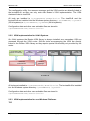
2.2.2 VISA Implementation for 64-bit Systems
On 64-bit systems the Bustec VISA library is always installed as a secondary VISA an
accessed through the VISA router. Still the tools accompanying the VISA are directly
linked to the Bustec VISA library as they require special functionality not provided by the
router.
Application and
Instrument Drivers
visa64.dll
VISA Router
VISA
Assistant
Conflict
Manager I/F
Configuration
Utility
Resource
Manager
VISA
Monitor
Conflict
Manager
buvisa64.dll
All tools are installed to $(VXIPNPPATH64)\WIN64\buvisa. The buvisa64.dll is installed
into the Windows system directory $(SYSTEMROOT)\system32.
Configuration data and other user writeable files are stored in
$(ALLUSERSPROFILE)\Bustec\buvisa.
2.2.3 VISA Implementation for non-Windows Platforms
TBD
Page 18 of 63
Copyright, © 2010 Bustec Production Ltd.
Bustec VISA User Manual
8200-XX-UM
2.2.4 VISA Extensions
The Bustec VISA implementation adds a number of binary compatible extensions to the
VISA standard. Definitions for those extensions can be found in the header file buvisa.h,
which is installed in the standard include directory by the Bustec VISA installer. This file is
common for all frameworks.
2.2.4.1 Support for 2eVME and 2eSST protocols
To support the advanced backplane protocols introduced with the VXIbus standard VXI-1
revisions 3 and 4, the Bustec VISA implementation adds four more access privileges to the
list of privileges which can be used to specify the way the functions viMoveInXX[Ex](),
viMoveOutXX[Ex](), viMove[Ex]() and viMoveAsync[Ex]() access the VXIbus.
The access mode must be selected using the function viSetAttribute() using the
attributes VI_ATTR_SRC_ACCESS_PRIV and VI_ATTR_DEST_ACCESS_PRIV prior to
using the functions.
2.3
Attribute Value
Selected Transfer Mode
BUVISA_D64_2eVME
A32/A64 2eVME D64 transfer
BUVISA_D64_SST160
A32/A64 2eSST D64 transfer, 160 MB/s
BUVISA_D64_SST267
A32/A64 2eSST D64 transfer, 267 MB/s
BUVISA_D64_SST320
A32/A64 2eSST D64 transfer, 320 MB/s
Installing the Bustec VISA Library
The installation procedure is the following:
1. Close all unnecessary applications running on your system and run the Bustec
VISA installer suitable for your system – 32 or 64-bit. The 32-bit version installs only
the 32-bit files, while the 64-bit one installs both versions.
Note
The best practice is to run the installer after fresh start of the system. In case if
there is already a 32-bit primary VISA installed, it ensures that there are no
applications or services running that keep lock on the visa32.dll file.
2. At the beginning, the IVI Shared Components package is installed (either a 32 or
64-bit version).
Copyright, © 2013 Bustec Ltd.
Page 19 of 63
8200-XX-UM
Bustec VISA User Manual
Figure 4 – Installation of the IVI Shared Components
3. When it’s done, the main part of the installer is started. First you have to read and
accept the license agreement. If you don’t agree to the terms you cannot install and
use Bustec VISA.
4. After the license agreement is accepted the files are copied to the disk and the
necessary configuration is done.
Figure 5 – Bustec VISA installation progress
5. When the installation is complete, the Bustec 32-bit Conflict Manager is started. It
finalizes the setup of the Bustec 32-bit VISA Router. If the visa32.dll file doesn’t
exist, it creates such – a Bustec router library. If the file already existed (third-party
primary VISA was previously installed), the tool renames it, sets up Bustec router as
the new visa32.dll and configures the multi-VISA environment. For more details
please refer to section 3.6.
6. It’s advised to restart the computer after the installation is complete.
Page 20 of 63
Copyright, © 2010 Bustec Production Ltd.
Bustec VISA User Manual
2.4
8200-XX-UM
Installing drivers for Slot-0 modules
The drivers for Bustec’s Slot-0 modules (like ProDAQ 3020 or ProDAQ 3030) are not
installed along with Bustec VISA. The installers are separate for each module.
The installation procedure is the following:
1. Close all unnecessary applications running on your system and run the installer
suitable for your system, either the 32 or 64-bit.
2. Read and accept the license agreement. If you don’t agree to the terms you cannot
install and use the package.
3. It’s now possible to define the target directory for the user-mode program and
library files. By default the VXIPNPPATH is used.
4. The installation process is started. The kernel driver installation requires an
additional acceptation due to the system’s security.
Figure 6 – Accepting kernel driver installation
5. It’s advised to restart the computer after the installation is complete.
Note
If you are not willing to restart the whole system, at least the Bustec Agent must be
restarted. Otherwise it won’t be able to detect hot-plug events.
Copyright, © 2013 Bustec Ltd.
Page 21 of 63
8200-XX-UM
Bustec VISA User Manual
3. Tools and Utilities
3.1
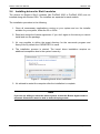
Bustec Agent
Bustec Agent is a light application that resides in the system tray. It does not link to the
VISA library. Agent gives easy and fast access to Bustec VISA tools, but also detects hotplug and other notification events from ProDAQ 3030 and ProDAQ 3020. Additionally, it
automatically detects network devices using mDNS facilities. To make use of the latter,
Bonjour library must be installed in the system (available at: www.apple.com).
Figure 7 – Bustec Agent
Figure 8 – Hot plug from ProDAQ 3030 detected
3.2
Configuration Utility
3.2.1 Handling Interfaces
The VISA library uses interface names and numbers to access available hardware
interfaces. An interface to a particular hardware is for example a ProDAQ VXIbus interface
connected to a host PC or an internal bus interface of a ProDAQ embedded controller. In
order to enable the VISA library to use an interface, which is connected to or used with a
host PC for the first time, a valid interface name and number must be assigned to this
device. The assigned interface name and number will be stored internally in the
configuration for interface together with its serial number and will be used for this device
whenever it is connected to or used with this host.
Page 22 of 63
Copyright, © 2010 Bustec Production Ltd.
Bustec VISA User Manual
8200-XX-UM
Note
If you want to assign and configure a ProDAQ VXIbus Slot-0 Interface like the
ProDAQ 3020 or the ProDAQ 3030 to be used with your computer, it must be
connected to your computer and powered on for the configuration utility to be able
to detect it.
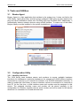
From the Bustec VISA program group created during the installation of the VISA library,
select “Bustec VISA Configuration Utility” (“Start” “Programs” “Bustec VISA”). This
will start the configuration tool for the VISA library and for the attached hardware
interfaces. Alternatively you can use a link in Bustec Agent.
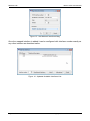
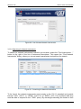
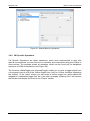
Figure 9 - VISA Library Configuration Utility
To add a new interface, select “Add Interfaces”. A new dialog “Add New Interface” is
shown with a list of all devices found in the system. The already configured are disabled.
Each interface is listed with its type and with a description containing the serial number of
the device.
Copyright, © 2013 Bustec Ltd.
Page 23 of 63
8200-XX-UM
Bustec VISA User Manual
Note
The optional on-board GPIB interface of a ProDAQ 3020 USB2.0 VXIbus Slot-0
Interface will appear in the list of devices as a separate interface of the type GPIB.
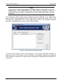
Figure 10 - Adding a new Interface
The interface numbers are assigned automatically from the pool of not yet used values. If
you want to change them, just select an interface and modify the value using the spin box
control in the bottom. Finally click “Add all” or “Add selected”. The list in the main dialog
will be updated with the newly added interfaces.
Figure 11 - List of configured interfaces
To remove the configuration for a device from the system, select the device in the list of
configured interfaces and select “Remove Interface”. To configure device-dependent
parameters of an interface, select “Configure Interface”, or double click on the list entry. If
Page 24 of 63
Copyright, © 2010 Bustec Production Ltd.
Bustec VISA User Manual
8200-XX-UM
you want to access a hot-plug device which was not connected when the configuration
utility was started, but was already configured on this system, the “Refresh List” button can
be used to update the list of configured interfaces.
Note
For a detailed explanation of device-dependent parameters, please refer to the user
manual of the ProDAQ interface or embedded controller.
Note
The configuration utility may not apply changes in the configuration to the
interfaces directly for some interfaces. In this case the new configuration will be
stored on your system and will be applied to the interface when the interface is first
used (i.e. by the resource manager or an application using the VISA library). Some
interfaces or some configuration settings may require the interface to be re-started
or the computer housing the interface to be re-booted before becoming active. For
detailed information for a particular interface, refer to the user manual of the
interface.
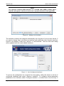
3.2.1.1 Mapping network interfaces
To gain access to all VXIbus instruments via a network Slot-0 Interface, like ProDAQ 3080,
it is recommended to map it as a standard VXIbus interface onto the host system. In order
to do it select “Map Network Interface” button in the “Add New Interface” dialog.
Figure 12 - Add New Interface Dialog – opening the mapping dialog.
In the "Map Network Interface" dialog you can specify the network address of the remote
interface and the local interface on the remote server to use. The TCPIP interface number
is a virtual value. It allows differentiation of TCPIP interfaces in case of conflict
management when there are multiple VISAs installed in the system.
Copyright, © 2013 Bustec Ltd.
Page 25 of 63
8200-XX-UM
Bustec VISA User Manual
Figure 13 - Add Network Interface dialog
Once the mapped interface is added it can be configured with interface number exactly as
any other interface as described earlier.
Figure 14 - Updated Available Interfaces List
Page 26 of 63
Copyright, © 2010 Bustec Production Ltd.
Bustec VISA User Manual
8200-XX-UM
Figure 15 – Updated list of configured interfaces
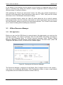
3.2.2 VXIbus Resource Manager Configuration
The configuration for the VXIbus Resource Manager can also be changed with the
configuration utility. In the configuration utility main panel select the “Resource Manager”
button on the right hand side. This will show the configuration dialog for the resource
manager.
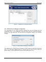
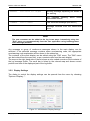
Figure 16 - VXIbus Resource Manager Configuration
Two parameters for VXIbus Resource Manager can be configured using the configuration
utility: The initial delay (default value is 5 seconds) and the path to ASCII output file
(default value is "$(ALLUSERSPROFILE)\Bustec\buvisa\buresman.out").
Copyright, © 2013 Bustec Ltd.
Page 27 of 63
8200-XX-UM
Bustec VISA User Manual
Caution
The initial resource manager delay as defined by the VXIbus standard must be in
minimum five (5) seconds. Configuring the resource manager to use a shorter delay
might not allow all devices to finish their initialization and self-test, preventing the
resource manager from identifying and configuring them.
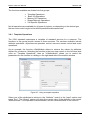
3.2.3 Network Instruments
3.2.3.1 Adding known Network Instruments
In addition to configuring hardware interfaces, the configuration utility allows you to search,
identify and configure network instruments. To view already known network instruments or
add new, select the “Network Instruments” tab in the configuration utilities main dialog.
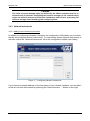
Figure 17 – Configuring Network Instruments
If you know the network address or the host name of your network interface, you can add it
to the list of known instruments by selecting the “Add Instrument ...” button on the right.
Page 28 of 63
Copyright, © 2010 Bustec Production Ltd.
Bustec VISA User Manual
8200-XX-UM
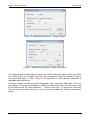
Figure 18 - Add Network Instrument – using host name
Figure 19 - Add Network Instrument – custom device name
The resulting resource descriptor is shown in the field “Descriptor” below. When you select
the “Verify” button to the right of the field, the configuration utility will attempt to open a
connection and send a “*IDN?” query to the instrument to verify that the instrument is
reachable and switched on.
All known network instruments will be displayed in the “Instrument Descriptor” list in the
main dialog. To change the settings for a particular instrument, select the instrument in the
list and then select the “Edit Instrument ...” button to the right. To remove an instrument
from the list, select the instrument in the list and then select the “Remove Instrument”
button.
Copyright, © 2013 Bustec Ltd.
Page 29 of 63
8200-XX-UM
Bustec VISA User Manual
Figure 20 - List of known Network Instruments
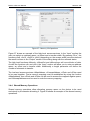
3.2.3.2 Searching for Network Instruments
To search for network instruments located in your subnet, select the “Find Instruments ...”
button to the right of the list of instrument descriptors. This opens the “Find Network
Instruments” dialog, where you can set search parameters and perform the search.
Figure 21 - Searching for Network Instruments
To be found, the network instruments must comply to the VXI-11 standard and provide
internal “VXIn” (VXI-11.1), “GPIBn” (VXI-11.2) or “INSTn” (VXI-11.3) interfaces and they
must be able to respond to the “*IDN?” query. By checking/unchecking the boxes in front
Page 30 of 63
Copyright, © 2010 Bustec Production Ltd.
Bustec VISA User Manual
8200-XX-UM
of the entries in the interface list the search can be limited to a particular type or set of
types of interfaces. By setting the interface number ranges the search is limited to the
selected range of interface numbers.
After selecting the “Search for Instruments” button, the utility uses network broadcasts to
search for the instruments. Each instrument is then sent an “*IDN?” query and the results
are shown in the “Find Network Instruments” dialog.
After a successful search, select the “Add All” button below the list to add all network
instruments found to the list of known instruments or select instruments from the list and
the “Add Selected” button to add only the instruments selected. The “Cancel” button allows
you to close the dialog without adding any instrument
3.3
VXIbus Resource Manager
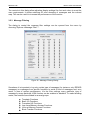
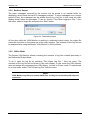
3.3.1 GUI Application
Before you can use the VISA library to communicate to the instruments, you must run the
resource manager. The resource manager finds VXI and GPIB instruments connected to
your PC and configures them. To run the resource manager, select “Bustec VXIbus
Resource Manager” from the Bustec VISA program group in the start menu (“Start”
“Programs” “Bustec VISA”) or use the link in Bustec Agent.
Figure 22 - Running the VXI Resource Manager
The Resource Manager configures all the Bustec Slot-0 modules found in the system –
even those not configured with Bustec VISA Configuration Utility. In such a case default
configuration and auto-selected interface number is set up.
Copyright, © 2013 Bustec Ltd.
Page 31 of 63
8200-XX-UM
Bustec VISA User Manual
When started, the Resource Manager waits for a while (as configured with Bustec VISA
Configuration Utility) to allow all devices to complete their initialization and finish self-tests
(if available). Then it performs the following functions:
1.
2.
3.
4.
5.
6.
Identify all VXIbus devices in the system.
Manage the system self-test and diagnostic sequence.
Configure the system’s A24 and A32 address maps.
Configure the system’s Commander/Servant hierarchies.
Allocate the VXIbus IRQ lines.
Initiate normal system operation.
Once finished, the information about the VXIbus devices found is made available for the
VISA library and a readable version of this information is saved to a file. Both the initial
delay and the location of the resource manager output file are configurable using the
configuration utility (see 3.2.2).
Note
To run the resource manager for a VXI mainframe connected via a ProDAQ Slot-0
Interface to your computer, the interface module must be located in the left most
slot (slot “0”) of the VXI mainframe and must be configured to use the logical
address 0 (00hex).
Note
To run the resource manager on a ProDAQ Embedded Slot-0 Controller for the VXI
mainframe it is located in, the controller module must be located in the left most
slot (slot “0”) of the VXI mainframe and must be configured to use the logical
address 0 (00hex).
Note
Although the ProDAQ 3020 USB 2.0 VXIbus Slot-0 Interface and the ProDAQ 3030
PCIExpress VXIbus Slot-0 Interface are hot-plug able, the resource manager cannot
dynamically add or remove devices from its device list. Therefore the resource
manager must be run every time a VXI mainframe is connected or disconnected
to/from your computer. There is also no protocol available to notify applications of
the configuration change. Running applications must be restarted after re-running
the resource manager
Caution
The initial resource manager delay as defined by the VXIbus standard must be in
minimum five (5) seconds. Configuring the resource manager to use a shorter delay
might not allow all devices to finish their initialization and self-test, preventing the
resource manager from identifying and configuring them.
Page 32 of 63
Copyright, © 2010 Bustec Production Ltd.
Bustec VISA User Manual
8200-XX-UM
Note
The VISA library is a shared library that initializes itself when it is first loaded by an
application. Applications started while the VISA library is already loaded just share
this configuration. Only when all applications using the VISA library are stopped, it
will be unloaded by the system. Therefore all applications using the VISA library
must be closed before running the resource manager or using the VISA
configuration utility. Take special care while using integrated development
environments, they will keep the VISA library loaded even when the application
developed in them was stopped.
3.3.2 Console Application
The resource manager of the Bustec VISA library is also available as console application
to support its automated usage in batch files, other applications and the startup folder. To
run the resource manager console application, use:
resman_con [-v|-s]
If the command line switch "-v" is used, the resource manager console application will print
out an overview of its progress and findings on the standard output, similar to the output in
the "Details" field of the GUI application.
The command line switch "-s" can be used to suppress all output to the standard output.
Once finished, the information about the VXIbus and GPIB devices found is made
available for the VISA library and a readable version of this information is saved to a file.
Both the initial delay and the location of the resource manager output file are configurable
using the Bustec VISA Configuration Utility.
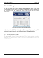
3.4
VISA Assistant
The VISA Assistant is an interactive tool, which allows executing VISA commands without
programming. To run the VISA Assistant, select “Bustec VISA Assistant” from the Bustec
VISA program group in the start menu (“Start” “Programs” “Bustec VISA”).
Alternatively you can also use a link in Bustec Agent.
The main window of the Visa Assistant shows a list of all VISA resources in the system.
Copyright, © 2013 Bustec Ltd.
Page 33 of 63
8200-XX-UM
Bustec VISA User Manual
Figure 23 - The VISA Assistant
On selecting one by double-clicking on its entry, the VISA Assistant opens a VISA session
for that device in a separate window.
Figure 24 - VISA Assistant Session Window
In the tree-view control on the left hand side you have access to information about the
session and the VISA functions possible for the resource.
Page 34 of 63
Copyright, © 2010 Bustec Production Ltd.
Bustec VISA User Manual
8200-XX-UM
The functions available are divided into five groups:
Template Operations
Basic I/O Operations
Memory I/O Operations
Shared Memory Operations
VXI Specific Operations
Not all operations are available for all types of devices, so depending on the device type,
the tree-view control might not list all the possibilities discussed here.
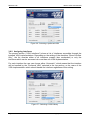
3.4.1 Template Operations
The VISA standard implements a template of standard services for a resource. The
functions in this group provide access to those services. The services available include
attribute operations, asynchronous operation control, resource access control and event
operations.
As an example, the function viGetAttribute allows to retrieve the values for attributes
defined for a resource. Selecting the function in the tree-view control on the left hand side
(click on "Template Operations", then on "viGetAttribute") allows you to control the
parameters for the function in a dialog on the right hand side of the session window
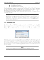
Figure 25 - Using a template operation
Select one of the attributes to retrieve in the “Attribute” control in the “Input” section and
press “Run”. The “Output” section will show the current value of the attribute in the control
“Attribute state”, if the operation was successful, and the returned status of the function.
Copyright, © 2013 Bustec Ltd.
Page 35 of 63
8200-XX-UM
Bustec VISA User Manual
3.4.2 Basic I/O Operations
The basic I/O operations will allow the user to send commands to a device and read back
its answer, to trigger the device or read its status.
Figure 26 - Using basic I/O operation
As an example, you can use the viRead function to read data or a message from the
device. To do so, just specify the maximum number of bytes to read from the device and
press “Run”. As before, the VISA Assistant will show the message read as well as the
returned status of the operation.
3.4.3 Memory I/O Operations
The memory I/O operations consist of High- and Low-Level Access services. The HighLevel Access Services allow register-level access to devices that support direct memory
access. They encapsulate most of the code required to perform the access, such as
window mapping, address translation and error checking. The Low-Level Access Services
are similar in purpose, but are implemented without the software overhead of the HighLevel Services.
Page 36 of 63
Copyright, © 2010 Bustec Production Ltd.
Bustec VISA User Manual
8200-XX-UM
Figure 27 - Memory I/O Operations
Figure 27 shows an example of the high-level access services. In the “Input” section the
user can select an address space, an offset and a transfer width. By pressing “Run”, the
functions viIn8, viIn16, viIn32 or viIn64 (depending on the access width) are executed and
the result is shown in the “Output” section of the dialog along with the returned status.
The high-level functions viMoveIn, viMoveOut and viMoveAsync will move blocks of data.
As with the functions viIn and viOut, the “Input” section will allow you to enter an address
space, an offset and a transfer width. Additionally a length parameter will define the
number of elements to transfer.
The low-level access services viMapAddress, viUnmapAddress, viPeek and viPoke need
to be used together. First a memory mapping must be established by using the function
viMapAddress, then viPeek and viPoke can be used to access the mapped register space,
and viUnmapAddress must be used to undo the memory mapping.
3.4.4 Shared Memory Operations
Shared memory operations allow allocating memory space on the device to be used
exclusively by the session allocating it. Figure 28 shows an example of the shared memory
operations.
Copyright, © 2013 Bustec Ltd.
Page 37 of 63
8200-XX-UM
Bustec VISA User Manual
Figure 28 - Shared Memory Operations
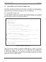
3.4.5 VXI Specific Operations
VXI Specific Operations are those operations, which were implemented to deal with
special circumstances you can find only on controller and instruments using the VXIbus to
communicate. The example shows an operation, which can be found only for backplane
resources of VXIbus mainframes (see Figure 29).
The functions viMapTrigger and viUnmapTrigger enable you to route a trigger signal from
a front panel input to one of the VXIbus trigger lines (only for VXIbus controller supporting
this feature). In the “Input” section you can select a source trigger line, which should be
mapped to a destination trigger line. As in the other examples, pressing “Run” will execute
the function and display the result in the “Output” section.
Page 38 of 63
Copyright, © 2010 Bustec Production Ltd.
Bustec VISA User Manual
8200-XX-UM
Figure 29 - VXI Specific Operations
3.5
VISA Monitor
The VISA monitor allows the tracing of function calls inside the Bustec VISA library. It
receives the generated trace messages and stores them into a log buffer. The key features
of the Bustec VISA Monitor are:
Works with standard Bustec VISA library, no need to recompile or re-link an
application to get the trace output
Traces the VISA calls from the remote target system over network allows to get
information from non-graphical platforms, like VxWorks
Possibility to store the trace output directly to a log file
Views previously created log files (off-line viewing)
Supports four different debug message types
Per-function and per-type message filtering to avoid the message flooding and loss
of system performance
User can add comments to the trace log both interactively from VISA Monitor and
from his program
3.5.1 Main Window
To run the Bustec VISA Monitor, select "Bustec VISA Monitor" from the Bustec VISA
program group in the start menu ("Start" "Programs" "Bustec VISA"). You can also
find a link in Bustec Agent.
Copyright, © 2013 Bustec Ltd.
Page 39 of 63
8200-XX-UM
Bustec VISA User Manual
Figure 30 – Bustec VISA Monitor
The main window shows a list of messages from the log buffer. Most recent messages are
always added to the bottom of the list. A message can have one of the following types:
Message
Description
/++++++++++\ viClose(3943168)
Trace message showing entry to the
function with call parameters values
\
Trace message showing VISA function
returning VI_SUCCESS
0/ viOpen
\0xbfff001d/ viGetAttribute
Trace message showing VISA function
returning VISA error
\0x3fff0003/ viDisableEvent
Trace message showing VISA function
returning VISA warning
ERROR:
Page 40 of 63
Invalid VISA object
Error message explaining the details of the
error
Copyright, © 2010 Bustec Production Ltd.
Bustec VISA User Manual
WARNING:
INFO:
8200-XX-UM
User buffer not aligned
Warning message explaining the details of
the warning
Device respond: "+0 No Error"
Info message showing
intermediate results
some
useful
COMMENT:
User's comment
User comment message (see Note 1)
KERN:
No buffer specified
Message received from the kernel-level
driver
Note
The user comment can be added to the log in two ways: interactively using the
“Edit” menu, or programmatically from the user application using buDebug(const
char *message) function.
Any message or group of continuous messages shown in the main display can be
selected. If the selected message contains some error/warning code, the appropriate
error/warning code explanation will be shown in the status bar.
The contents of the main display can be edited using the "Edit" menu. The "Edit" menu
can be invoked from the menu bar, or as a context menu from the main display.
The map on the right hand side of the list shows a color-coded overview of the contents of
the log message buffer. The scroll bar is linked to the colored map and shows current
position and size of the displayed part of the log buffer.
3.5.2 Display Settings
The dialog to control the display settings can be opened from the menu by choosing
"Options->Display...".
Figure 31 - VISA Monitor Display Settings
Copyright, © 2013 Bustec Ltd.
Page 41 of 63
8200-XX-UM
Bustec VISA User Manual
The controls in this dialog allow adjusting display settings like font and colors to meet the
user requirements. It allows switching off color decoding of messages and the colored
map. This can be useful to increase the performance of the monitor.
3.5.3 Message Filtering
The dialog to control the message filter settings can be opened from the menu by
choosing "Options->Message Filter...".
Figure 32 - Message Filtering Dialog
Sometimes it is important to log only certain type of messages (for instance, only ERROR
messages) or messages from specific functions to avoid a flood of messages and, as a
result, a loss of system performance. Via the filter settings every particular type of
message for every particular VISA function can be enabled or disabled. To make handling
easier, the functions are divided in several groups:
Template Functions
Basic I/O Functions
Formatted I/O Functions
Low-Level Memory Access Functions
Hi-Level Memory Access Functions
Block Transfer Functions
Page 42 of 63
Copyright, © 2010 Bustec Production Ltd.
Bustec VISA User Manual
8200-XX-UM
Shared Memory Functions
Internal Bustec VISA Functions
Every function group is placed in a separate tab. The "Select All" and "Clear All" buttons in
the tab will switch on/off all message types for all functions in the group. The "All"
checkbox switches on/off all message types for a particular function.
The display and filter settings can be saved and restored from the "File" menu (File ->
Save/Load Settings...).
Note
By default all messages from internal Bustec VISA functions are switched off as
they contain very specific information. However, if the Bustec support was
requested, the support team may ask to send log file after run debugging program
with this options switched on.
3.5.4 Remote VISA Mode
By default, the Bustec VISA Monitor will connect to the local VISA library, i.e. the VISA
library installed on the same computer. To receive trace messages from a remote VISA (a
Bustec VISA library running on a machine connected via network), select
"Options->Remote VISA..." from the menu and enter the IP address of the remote
machine.
Figure 33 - Remote VISA Access Dialog
Enable the remote access to the target VISA and press "OK" button. The VISA monitor will
try to establish a network connection to the agent running on the remote system. Once the
connection is established, a pop-up message will report the successful connection. When
the connection is broken, another pop-up message will appear. All the time, while the VISA
Monitor is working in remote mode, the target IP address will be shown in the status bar of
the main window.
Note
Currently remote VISA access is not implemented for Windows platforms
Copyright, © 2013 Bustec Ltd.
Page 43 of 63
8200-XX-UM
Bustec VISA User Manual
3.5.5 Redirect Output
The trace messages received by the monitor will be stored in an internal buffer for
displaying, which holds the last 512 messages received. To store messages over a longer
period of time, the messages can be written directly to a log file. In this mode the main
display doesn't show the messages. To do so, choose "File->Start Logging to File..." from
the menu, select a target file and press the “Start” button.
Figure 34 - Redirecting Output
All the time while the VISA Monitor is working in redirected output mode, the output file
name will be shown in the status bar of the main window. The contents of the log file can
be analyzed later using the Bustec VISA Monitor in Off-line Mode.
3.5.6 Offline Mode
The Bustec VISA Monitor allows reviewing the contents of log files created previously in
the Redirected Output Mode.
To do it, open the log file by selecting "File->Open Log File..." from the menu. The
contents of the log file will be shown in the main display. In this mode the VISA Monitor
does not accept any messages from VISA library, it works in off-line mode. To switch back
to on-line mode, select "File->Close Log File" from the menu.
Note
VISA Monitor log files are normal ASCII files, so they can be handled with any text
processor.
Page 44 of 63
Copyright, © 2010 Bustec Production Ltd.
Bustec VISA User Manual
3.6
8200-XX-UM
Conflict Manager
To start the Bustec VISA Conflict Manager interface application, select “VISA 64-bit
Conflict Manager” from the Bustec VISA program group created during the installation of
the VISA library (“Start” “Programs” “Bustec VISA”). You can also use a link in
Bustec Agent.
Figure 35 - Bustec VISA Conflict Manager Interface
In the top section (“VISA Libraries”), the conflict manager displays a list of VISA
implementations present in the system. By checking/unchecking the checkboxes to the
right of each VISA the particular VISA implementations can be enabled/disabled.
3.6.1 Selecting the Preferred VISA
The setting for the “Preferred VISA" decides which VISA will handle interfaces accessible
via multiple VISA implementations, except for interfaces manually assigned to a particular
VISA (see below).
Copyright, © 2013 Bustec Ltd.
Page 45 of 63
8200-XX-UM
Bustec VISA User Manual
Figure 36 - Selecting a preferred VISA
3.6.2 Assigning Interfaces
The second section (“VISA Interfaces”) shows a list of interfaces accessible through the
installed VISA implementations. Depending on the setting of the checkbox “Show Conflicts
Only”, the list consists either of all interfaces present (box unchecked) or only the
interfaces which can be accessed via more than one VISA implementation.
For each interface the user can choose either “Automatic”, which means that the interface
will be handled by the “Preferred VISA” selected in the top section, or the name of the
VISA implementation which should handle the interface regardless of this setting.
Figure 37 - Selecting a VISA Library
Page 46 of 63
Copyright, © 2010 Bustec Production Ltd.
Bustec VISA User Manual
8200-XX-UM
Note
If “Automatic” is chosen, the selection is immediately updated to show the
resulting choice (i.e. the name of the VISA selected as “Preferred VISA”). Whether
this setting is the result of a manual or automatic assignment is displayed to the
right of the selection.
For more information about the VISA router, the conflict manager and the conflict
resolution, see chapter 2.1.2: The VISA Router and VPP-4.3.5: VISA Shared Components.
3.6.3 32-bit VISA
IVI Foundation provides only 64-bit VISA router library, so conflict resolving is done only
for the 64-bit applications linked with VISA. Bustec provides similar implementation of the
router library for 32-bit VISAs. Therefore conflict management can also be done for 32-bit
applications.
The 32-bit Conflict Manager, as compared to its 64-bit counterpart, has an additional,
semi-auto configuration capability. The configuration check is done on each start of the
application. In case of inconsistency, the user is notified and can decide what to do.
Mainly, there are two situations possible:
The visa32.dll file does not exist – there is no other VISA in the system, or a thirdparty primary VISA was removed causing the previously properly installed Bustec
32-bit VISA Router (visa32.dll) to be deleted.
The visa32.dll is a third-party primary VISA library – it might have been installed
before Bustec VISA, or later, overwriting Bustec 32-bit VISA Router.
You should run the Bustec 32-bit VISA Conflict Manager each time installing, reinstalling,
or uninstalling other VISAs. Bustec VISA installer starts the program automatically as the
last step of the process.
The first situation (no visa32.dll file) is handled by the Conflict Manager by just creating the
visa32.dll file – Bustec 32-bit VISA Router library.
Figure 38 – Bustec 32-bit VISA Conflict Manager – no visa32.dll found
Second problem is resolved by renaming the visa32.dll (third party primary VISA) and
setting up new visa32.dll – the Bustec 32-bit VISA Router.
Copyright, © 2013 Bustec Ltd.
Page 47 of 63
8200-XX-UM
Bustec VISA User Manual
Figure 39 – Bustec 32-bit VISA Conflict Manager, third party primary VISA detected
Figure 40 – Bustec 32-bit VISA Conflict Manager – renaming VISA library
When the problem is resolved, the 32-bit Conflict Manager starts to work exactly as the 64bit version.
Figure 41 – Bustec 32-bit VISA Conflict Manager
Page 48 of 63
Copyright, © 2010 Bustec Production Ltd.
Bustec VISA User Manual
8200-XX-UM
(This page was intentionally left free)
Copyright, © 2013 Bustec Ltd.
Page 49 of 63
8200-XX-UM
Bustec VISA User Manual
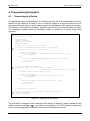
4. Programming Examples
4.1
Connecting to a Device
An application using the VISA library to communicate with the instrument needs to open a
session for the resource it wants to use. A resource might be a physical resource as for
example a VXI instrument or virtual resources like the backplane or the resource manager.
The session will handle all accesses, attributes and services for the particular resource.
The following example shows all necessary steps to connect to a device using VISA
functions:
#include <visa.h>
main (int argc, char **argv)
{
ViStatus status;
ViSession rm_session;
ViSession instr_session;
ViChar descr[256];
/* open a session to the resource manager */
if ((status = viOpenDefaultRM (&rm_session)) != VI_SUCCESS)
{
viStatusDesc (rm_session, status, descr);
if (status > VI_SUCCESS)
printf (“VISA WARNING: viOpenDefaultRM returned status %08x (%s)\n”,
status, descr);
else
{
printf (“VISA ERROR: viOpenDefaultRM returned status %08x (%s)\n”,
status, descr);
return status;
}
}
/* open a session to the instrument */
if ((status = viOpen (rm_session, “VXI0::2::INSTR”,
VI_NULL, VI_NULL, &instr_session)) != VI_SUCCESS)
{
viStatusDesc (instr_session, status, descr);
if (status > VI_SUCCESS)
printf (“VISA WARNING: viOpen returned status %08x (%s)\n”,
status, descr);
else
{
printf (“VISA ERROR: viOpen returned status %08x (%s)\n”,
status, descr)
return status;
}
}
/* accessing the instrument */
/* close the sessions to the instrument and the resource manager */
viClose (instr_session);
viClose (rm_session);
}
Figure 42 - Opening a VISA Session
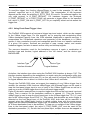
The first step in a program, which uses the VISA library, is always to open a session to the
default resource manager (). It provides connectivity to all VISA resources registered
with it and gives applications control and access to individual resources.
Page 50 of 63
Copyright, © 2010 Bustec Production Ltd.
Bustec VISA User Manual
8200-XX-UM
The next step is to open a session to the instrument or multiple sessions to multiple
instruments (). The resource name used is a combination of interface type and number,
logical address of the VXI device, and a device type:
VXI 0 :: 2 :: INSTR
Interface Type
Interface Number
Device Type
Logical Address
The interface type for the ProDAQ 3030 PCI Express VXIbus Interface is always “VXI”.
The interface number is the number, which was assigned to the particular ProDAQ 3030
by using the VISA configuration utility (see 2.6). The logical address of a VXI device is
defined either statically by setting its logical address switch, or dynamically during runtime
by the resource manager. If the resource manager assigned the address dynamically, the
actual assignment can be found in the output file of the resource manager (see 2.8.1). The
device type for VXI instruments is always “INSTR”.
Note
When running the above example, please make sure that the logical address used
in it matches the logical address setting of the instrument you want to connect to.
Note
Before you can use the above example to connect to your device, you must run the
VXI Resource Manager (see 2.8.1 – Running the VXIbus Resource Manager).
4.2
Programming Register-based Devices
Register-based devices are devices implementing a set of registers in A16 and often in
A24 or A32. Programming register-based devices is done by reading and writing these
registers to change their contents, either by bit, in groups of bits or in whole.
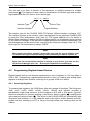
4.2.1 Accessing Registers
To access single registers, the VISA library offers two groups of functions. The first group,
viIn8, viIn16, viIn32, viIn64, viOut8, viOut16, viOut32 and viOut64, provides a
standardized, single word access to a device register in A16, A24 or A32 space. Figure 43
shows an example of a function reading a value from a device register (), modifying the
value read and writing it back (). The driver for the ProDAQ 3030 will automatically take
care about byte ordering, i.e. it will swap the words to be read or written between the littleendian host byte ordering your PC is using to the big-endian byte ordering used on the
VXIbus.
Copyright, © 2013 Bustec Ltd.
Page 51 of 63
8200-XX-UM
Bustec VISA User Manual
ViStatus function rmw_register (ViSession instr_session, ViBusAddress offset, ViUInt16 mod)
{
ViStatus status;
ViChar descr[256];
ViUInt16 value;
if ((status = viIn16 (instr_session, VI_A16_SPACE, offset, &value) != VI_SUCCESS)
{
viStatusDesc (instr_session, status, descr);
if (status
printf
else
{
printf
return
}
> VI_SUCCESS)
(“VISA WARNING: viIn16 returned status %08x (%s)\n”, status, descr);
(“VISA ERROR: viIn16 returned status %08x (%s)\n”, status, descr);
status;
}
value = value | mod;
if ((status = viOut16 (instr_session, VI_A16_SPACE, offset, value) != VI_SUCCESS)
{
viStatusDesc (instr_session, status, descr);
if (status
printf
else
{
printf
return
}
> VI_SUCCESS)
(“VISA WARNING: viOut16 returned status %08x (%s)\n”, status, descr);
(“VISA ERROR: viOut16 returned status %08x (%s)\n”, status, descr);
status;
}
return VI_SUCCESS;
}
Figure 43 - Memory-based I/O
The second group of functions is intended to map a register range into the memory of the
host and accessing it directly. Because this ability is architecture and system dependent,
the VISA standard foresees an attribute, which allows determining whether the range
could be physically mapped or the system architecture does not allow it. Depending on the
value of the attribute VI_ATTR_WIN_ACCESS, the range mapped can be directly
accessed (e.g. by using a C-style pointer), or the functions viPeek8, viPeek16, viPeek32,
viPeek64, viPoke8, viPoke16, viPoke32 and viPoke64 must be used to access registers in
the mapped range. Figure 44 shows the same function as in Figure 43, this time
implemented with memory mapping functions.
Page 52 of 63
Copyright, © 2010 Bustec Production Ltd.
Bustec VISA User Manual
8200-XX-UM
ViStatus function rmw_register (ViSession instr_session, ViBusAddress offset, ViUInt16 mod)
{
ViStatus status;
ViChar descr[256];
ViAddr address;
ViUInt16 win_access;
ViUInt16 value;
(instr_session, VI_A32_SPACE, offset,
if ((status = viMapAddress
sizeof (ViUInt16), VI_FALSE, (ViAddr) 0, &address)) != VI_SUCCESS)
{
viStatusDesc (instr_session, status, descr);
if (status > VI_SUCCESS)
printf (“VISA WARNING: viMapAddress returned status %08x (%s)\n”,
status, descr);
else
{
printf (“VISA ERROR: viMapAddress returned status %08x (%s)\n”,
status, descr);
return status;
}
}
(instr_session,
if ((status = viGetAttributeVI_ATTR_WIN_ACCESS,
&win_access)) != VI_SUCCESS)
{
viStatusDesc (instr_session, status, descr);
if (status > VI_SUCCESS)
printf (“VISA WARNING: viGetAttribute returned status %08x (%s)\n”,
status, descr);
else
{
printf (“VISA ERROR: viGetAttribute returned status %08x (%s)\n”,
status, descr);
return status;
}
}
if (win_access == VI_DEREF_ADDR)
{
/* allowed to use pointer or similar */
value = *((volatile ViUInt16 *) address);
value = value | mod;
*((volatile ViUInt16 *) address) = value;
}
else if (win_access == VI_USE_OPERS)
{
/* use functions to access memory */
viPeek16 (instr_session, address, &value);
value = value | mod;
viPoke16 (instr_session, address, value);
}
if{ ((status = viUnmapAddress (instr_session) != VI_SUCCESS)
viStatusDesc (instr_session, status, descr);
if (status > VI_SUCCESS)
printf (“VISA WARNING: viUnmapAddress returned status %08x (%s)\n”,
status, descr);
else
{
printf (“VISA ERROR: viUnmapAddress returned status %08x (%s)\n”,
status, descr);
return status;
}
}
return VI_SUCCESS;
}
Figure 44 - Register I/O using memory mapping
Copyright, © 2013 Bustec Ltd.
Page 53 of 63
8200-XX-UM
Bustec VISA User Manual
In the above example, the function viMapAddress is used to map a register range starting
with offset and extending over the size of the register into the memory of the host (). If
this is successful, the attribute “VI_ATTR_WIN_ACCESS” is checked to see whether the
controller was able to map the address range physically into the memory space of the
controller, or whether the mapping was done only logically (). If the mapping was done
physically, the application is allowed to use the address the register range is mapped to,
as if it is accessing its own memory. So for example C-style pointers may be used to
change the register value (). If the mapping was done only logically, the application need
to use the functions viPeek and viPoke provided by the VISA library to access the mapped
register range (). The VISA library will use the stored values for the mapped offset and
range to calculate the physical address and execute a single access in the same way as
internally done for the high-level functions. The function viUnmapAddress must be used to
undo the mapping of the register range (). Only one mapping per session is allowed by
the VISA standard. Please not that the functions viPeek and viPoke will work in both cases
(VI_ATTR_WIN_ACCESS equal to VI_DEREF_ADDR or equal to VI_USE_OPERS), but
will introduce a slightly higher overhead then using direct access if possible.
4.2.2 Moving Blocks of Data
To move blocks of data between an instruments memory and the host memory, the VISA
library implements the functions viMoveIn and viMoveOut for different transfer sizes. In
addition a number of attributes can be used to define the type of transfer performed on the
VXIbus.
#include <visa.h>
/* buffer used to store data from the instrument */
ViUInt16 data[1024];
main (int argc, char **argv)
{
ViStatus status;
ViSession rm_session;
ViSession instr_session;
ViChar descr[256];
ViUInt16 value;
/* open a session to the resource manager and instrument
* as shown in Figure 42 - Opening a VISA Session (not shown here) */
. . . .
/* now move a block of 16-bit data from the instrument to the buffer */
if ((status = viMoveIn16 (instr_session,
VI_A32_SPACE, MEM_START, 1024, data) != VI_SUCCESS)
{
viStatusDesc (instr_session, status, descr);
if (status
printf
else
{
printf
return
}
> VI_SUCCESS)
(“VISA WARNING: viMoveIn16 returned status %08x (%s)\n”, status, descr);
(“VISA ERROR: viMoveIn16 returned status %08x (%s)\n”, status, descr);
status;
}
/* close the sessions as shown in Figure 42 - Opening a VISA Session */
. . . . .
}
Figure 45 - Moving a Block of Data
Page 54 of 63
Copyright, © 2010 Bustec Production Ltd.
Bustec VISA User Manual
8200-XX-UM
For each move, one or several packets of data are moved over the VXIbus to the ProDAQ
3030 and via the PCI Express link between the ProDAQ 3030 and the host computer.
The type of transfer used on the VXIbus depends on the value of several attributes:
VI_ATTR_SRC_PRIV
for data moved from a VXIbus instrument to the host
VI_ATTR_DEST_PRIV
for data moved from the host to a VXIbus instrument
Only if the value of those attributes are set correctly prior to moving the data via viMoveIn
or viMoveOut, a block transfer on the VXIbus will take place. The following table shows the
type of transfers performed by the viMoveIn, viMoveOut and viMove functions for the
different values of the attributes:
Settings
Attribute
VI_DATA_PRIV
VI_DATA_NPRIV
VI_PROG_PRIV
VI_PROG_NPRIV
VI_BLCK_PRIV
VI_BLCK_NPRIV
VI_D64_PRIV
VI_D64_NPRIV
VI_D64_2eVME
VI_D64_SST160
VI_D64_SST267
VI_D64_SST320
Address Space
VI_A16_SPACE
VI_A24_SPACE
VI_A32_SPACE
VI_A16_SPACE
VI_A24_SPACE
VI_A32_SPACE
VI_A16_SPACE
VI_A24_SPACE
VI_A32_SPACE
VI_A16_SPACE
VI_A24_SPACE
VI_A32_SPACE
VI_A16_SPACE
VI_A24_SPACE
VI_A32_SPACE
VI_A16_SPACE
VI_A24_SPACE
VI_A32_SPACE
VI_A16_SPACE
VI_A24_SPACE
VI_A32_SPACE
VI_A16_SPACE
VI_A24_SPACE
VI_A32_SPACE
VI_A32_SPACE
VI_A32_SPACE
VI_A32_SPACE
VI_A32_SPACE
Resulting Transfer
Privilege
Data/Program
Supervisory Supervisory Data
Supervisory Data
Non-priv.
Non-priv.
Data
Non-priv.
Data
Supervisory Supervisory Program
Supervisory Program
Non-priv.
Non-priv.
Program
Non-priv.
Program
Supervisory Supervisory Supervisory Non-priv.
Non-priv.
Non-priv.
Supervisory Supervisory Supervisory Non-priv.
Non-priv.
Non-priv.
-
Block Transfer
BLT
BLT
BLT
BLT
MBLT
MBLT
MBLT
MBLT
2eVME
2eSST
2eSST
2eSST
AM(hex)
2D
3D
0D
29
39
09
2D
3E
0E
29
3A
0A
2D
3F
0F
29
3B
0B
2D
3C
0C
29
38
08
20/01
20/11
20/11
20/11
Figure 46 - VXIbus transfer types
Block transfers are performed on the VXIbus only if the correct attribute
(VI_ATTR_SRC_PRIV or VI_ATTR_DEST_PRIV, depending on the direction) is set to one
of the types VI_BLCK_PRIV, VI_BLCK_NPRIV, VI_D64_PRIV or VI_D64_NPRIV. The
data width of the performed transfer depends on the viMoveXX function used, except for
the case that the attribute is set to any of the VI_D64_* values, in which case a D64
transfer is performed.
Copyright, © 2013 Bustec Ltd.
Page 55 of 63
8200-XX-UM
Bustec VISA User Manual
#include <visa.h>
ViUInt16 data[1024];
/* buffer used to store data */
main (int argc, char **argv)
{
ViStatus status;
ViSession rm_session;
ViSession instr_session;
ViChar descr[256];
ViUInt16 value;
/* open a session to the resource manager and instrument
* as shown in Figure 42 - Opening a VISA Session (not shown here) */
/********************************************************************************/
/* Perform a 16-bit wide block transfer from a VXIbus instrument to the host
*/
/********************************************************************************/
/* set the correct attribute – VI_ATTR_SRC_PRIV for moving data IN */
if ((status = viSetAttribute (instr_session,
VI_ATTR_SRC_PRIV, VI_BLK_PRIV)) != VI_SUCCESS)
{
/* handle errors or warnings (not shown here) */
}
/* now move a block of 16-bit data from the instrument to the buffer */
if ((status = viMoveIn16 (instr_session,
VI_A32_SPACE, MEM_START, 1024, data) != VI_SUCCESS)
{
/* handle errors or warnings (not shown here) */
}
/********************************************************************************/
/* Perform a 32-bit wide block transfer from the host to a VXIbus instrument
*/
/********************************************************************************/
/* set the correct attribute – VI_ATTR_DEST_PRIV for moving data OUT */
if ((status = viSetAttribute (instr_session,
VI_ATTR_DEST_PRIV, VI_BLK_PRIV)) != VI_SUCCESS)
{
/* handle errors or warnings (not shown here) */
}
/* now move a block of 32-bit data from the instrument to the buffer */
if ((status = viMoveOut32 (instr_session,
VI_A32_SPACE, MEM_START, 1024, data) != VI_SUCCESS)
{
/* handle errors or warnings (not shown here) */
}
/********************************************************************************/
/* Perform a 64-bit wide block transfer from the host to a VXIbus instrument
*/
/********************************************************************************/
/* set the correct attribute – VI_ATTR_DEST_PRIV for moving data OUT */
if ((status = viSetAttribute (instr_session,
VI_ATTR_DEST_PRIV, VI_D64_PRIV)) != VI_SUCCESS)
{
/* handle errors or warnings (not shown here) */
}
/* now move a block of 64-bit data from the instrument to the buffer */
if ((status = viMoveOut32 (instr_session,
VI_A32_SPACE, MEM_START, 1024, data) != VI_SUCCESS)
{
/* handle errors or warnings (not shown here) */
}
/* close the sessions as shown in Figure 42 - Opening a VISA Session */
}
Figure 47 - Performing VXIbus Block Transfers
Page 56 of 63
Copyright, © 2010 Bustec Production Ltd.
Bustec VISA User Manual
4.3
8200-XX-UM
Programming Message-based Devices
Message-based VXIbus devices implement the word serial protocol to communicate with
the application. Programming is done by sending ASCII messages to the device and
reading its answer.
4.3.1 Writing and Reading Messages
The basic functions to write and read messages to/from devices are the two functions
viRead and viWrite. They implement the word serial protocol for message based devices,
but they do so on a very basic level. The user needs to build his message and use viWrite
to send it to the device. Then he uses viRead to receive the message sent back. The
message received might consist of strings, numbers and formatting characters and he will
need to interpret this message. To avoid some of these steps, a couple of higher level
functions were implemented in the VISA.
The following example shows how to use the functions viPrintf and viScanf to read the
identification of a device:
#include <visa.h>
main (int argc, char **argv)
{
ViStatus status;
ViSession rm_session;
ViSession instr_session;
ViChar descr[256];
/* open a session to the resource manager */
if ((status = viOpenDefaultRM (&rm_session)) != VI_SUCCESS)
{
/* error handling as shown in the previous examples !*/
}
/* open a session to the instrument */
if ((status = viOpen (rm_session, “VXI0::2::INSTR”,
VI_NULL, VI_NULL, &instr_session)) != VI_SUCCESS)
{
/* error handling as shown in the previous examples !*/
}
/* reset the device */
if ((status = viPrintf (vi, “*RST\n”)) != VI_SUCCESS)
{
/* error handling as shown in the previous examples !*/
}
/* ask the device for its identification */
if ((status = viPrintf (vi, “*IDN?\n”)) != VI_SUCCESS)
{
/* error handling as shown in the previous examples !*/
}
/* read the identification sent back */
if ((status = viScanf (vi, “%256t”, descr)) != VI_SUCCESS)
{
/* error handling as shown in the previous examples !*/
}
printf (“Device Identification: %s\n”, descr);
/* close the sessions to the instrument and the resource manager */
viClose (instr_session);
viClose (rm_session);
}
Figure 48 - Reading the Device Identification
Copyright, © 2013 Bustec Ltd.
Page 57 of 63
8200-XX-UM
Bustec VISA User Manual
The functions ViPrintf and viScanf use a C-style formatting string to format and scan
messages send to and read from the device, freeing the user from the separate steps
necessary to do so, if using the lower level function viWrite and viRead. Furthermore the
functions implement an extended set of formatting styles specially shaped towards
instrument communication.
In the above example the function viPrintf is used to send two messages to the device, first
a command to reset the device (), then a request to send back its identification string
(). viPrinf uses the format string together with the other arguments passed to it to build a
message string in a local buffer and then it calls viWrite to send this message to the
device.
The example program reads the identification using the function viScanf (). ViScanf
allocates a local buffer, calls the function viRead to receive the message from the device
and then it parses the message using the formatting supplied by the format string. In the
example the format code “%t” together with a size modifier is used, telling viScanf to
expect a string to be returned in the message, and to copy a maximum of 256 characters
into the buffer supplied.
The VISA standard supports a wide range of formatted I/O services like the viPrintf/viScanf
functions shown in the example. Please refer to the VISA standard document
“VXIplug&play Systems Alliance VPP-4.3: The VISA library” for a complete list.
4.4
Optimizing Programs
To optimize you programs using the ProDAQ 3030 PCI Express VXIbus Slot-0 Interface,
please keep the following in mind:
Use the functions viMove, viMoveIn or viMoveOut instead of single read and write
commands for devices and register ranges, wherever this is possible.
Use the attributes VI_ATTR_SRC_PRIV and VI_ATTR_DEST_PRIV to specify
block transfer privileges for devices where this is possible.
Use 32-bit or 64-bit moves, whenever possible.
Align your buffers to 32-bit boundaries. Locking this buffer in memory and allocating
a contiguous buffer will help to optimize the performance.
For maximum single word transfer performance, use viMapAdress and direct
memory access via C-style pointer or similar.
Page 58 of 63
Copyright, © 2010 Bustec Production Ltd.
Bustec VISA User Manual
4.5
8200-XX-UM
Using VXIbus and Front Panel Trigger Lines
One feature, that differs the VXIbus from other busses, is its ability to use trigger signals to
communicate with instruments in real-time, to share clock signals, etc. The VISA library
implements functions to control those trigger lines from your application.
4.5.1 Using VXIbus Trigger Lines
The VISA standard implements the function viAssertTrigger together with the attribute
VI_ATTR_TRIG_ID to assert and de-assert trigger lines on the VXIbus or sending the
word serial trigger command to message-based devices.
#include <visa.h>
main (int argc, char **argv)
{
ViStatus status;
ViSession rm_session;
ViSession instr_session;
ViChar descr[256];
/* open a session to the resource manager */
if ((status = viOpenDefaultRM (&rm_session)) != VI_SUCCESS)
{
/* error handling as shown in the previous examples !*/
}
/* open a session to the instrument */
if ((status = viOpen (rm_session, “VXI0::2::INSTR”,
VI_NULL, VI_NULL, &instr_session)) != VI_SUCCESS)
{
/* error handling as shown in the previous examples !*/
}
/* defining the trigger line to use */
if ((status = viSetAttribute (instr_session,
VI_ATTR_TRIG_ID, VI_TRIG_TTL0)) != VI_SUCCESS)
{
/* error handling as shown in the previous examples !*/
}
/* send a trigger pulse to the device */
if ((status = viAssertTrigger (instr_session, VI_TRIG_PROT_SYNC)) != VI_SUCCESS)
{
/* error handling as shown in the previous examples !*/
}
/* close the sessions to the instrument and the resource manager */
viClose (instr_session);
viClose (rm_session);
}
Figure 49 - Sending a Trigger Pulse
Figure 49 shows an example for sending a trigger pulse to a device. The function
viSetAttribute is used () to set the attribute VI_ATTR_TRIG_ID to select the trigger line.
In general the trigger ID can be set to VI_TRIG_TTL0 to VI_TRIG_TTL7,
VI_TRIG_ECL0/VI_TRIG_ECL1 or VI_TRIG_SW. For the setting VI_TRIG_SW, the device
is sent the word serial trigger command, the other settings correspond to the VXIbus
trigger lines TTL0-TTL7 and ECL0/ECL1.
Copyright, © 2013 Bustec Ltd.
Page 59 of 63
8200-XX-UM
Bustec VISA User Manual
To send the trigger, the function viAssertTrigger is used in the example () with the
“protocol” argument set to VI_PROT_DEFAULT. The interpretation of this argument
depends on the value, the attribute VI_ATTR_TRIG_ID is set to. For software triggers, the
only valid protocol is VI_PROT_DEFAULT. For hardware triggers, the protocols
VI_PROT_DEFAULT or VI_PROT_SYNC will generate a trigger pulse on the specified
line, while VI_PROT_ON and VI_PROT_OFF let you explicitly assert and de-assert the
trigger line.
4.5.2 Using Front-Panel Trigger Lines
The ProDAQ 3030 supports a front-panel trigger input and output, which can be mapped
to the VXIbus trigger lines. For this purpose, as for querying and manipulating other
VXIbus backplane specific lines, the VISA standard implements a special resource. It
encapsulates the VXI-defined operations and properties of the backplane in a VXIbus
system. It lets a controller to query and manipulate specific lines on a specific mainframe
in a given VXI system. Services are provided to map, unmap, assert, and receive
hardware triggers, and also to assert various utility and interrupt signals.
The resource descriptor used for the backplane resource is again a combination of
interface type and number, logical address of the VXI device, and the device type
BACKPLANE:
VXI 0 :: 0 :: BACKPLANE
Interface Type
Interface Number
Device Type
Logical Address
As before, the interface type when using the ProDAQ 3030 Interface is always “VXI”. The
interface number depends on the assignment you made using the configuration utility (see
2.6). The logical address will be zero (0), as you will need to configure the ProDAQ 3030
for logical address zero to allow it to function as a VXIbus slot-0 controller.
Though the ProDAQ 3030 does not support the mapping of one VXIbus trigger line to
another, the standard VISA functions viMapTrigger and viUnmapTrigger can be used to
map the front panel trigger input to one or many of the VXIbus trigger lines as well as to
map one or many VXIbus trigger lines to the front panel trigger output.
Figure 50 shows an example how to map the trigger lines to/from the front panel input and
output. First a session for the backplane resource is opened (). Then the function
viMapTrigger is used to map the front panel input to the VXIbus trigger line TTL1 (), and
also to the VXIbus trigger lines ECL0 (). This means that whenever an active trigger is
detected on the front panel input of the ProDAQ 3030, both lines will be asserted. In
general, when the viMapTrigger function is called multiple times with the same source
trigger line and different destination trigger lines, an assertion of the source line will cause
all of those destination lines to be asserted. To map one or multiple of the VXIbus trigger
lines to the front panel output, the value VI_TRIG_PANEL_OUT must be used for the
destination parameter (). As with the front panel input, multiple lines can be mapped to
Page 60 of 63
Copyright, © 2010 Bustec Production Ltd.
Bustec VISA User Manual
8200-XX-UM
the front panel output. When calling viMapTrigger multiple times with the same destination
line and different source lines, the destination line will be asserted when any of the source
lines is asserted.
#include <visa.h>
main (int argc, char **argv)
{
ViStatus status;
ViSession rm_session;
ViSession instr_session;
ViChar descr[256];
/* open a session to the resource manager */
if ((status = viOpenDefaultRM (&rm_session)) != VI_SUCCESS)
{
/* error handling as shown in the previous examples !*/
}
/* open a session to the instrument */
if ((status = viOpen (rm_session, “VXI0::0::BACKPLANE”,
VI_NULL, VI_NULL, &instr_session)) != VI_SUCCESS)
{
/* error handling as shown in the previous examples !*/
}
/* mapping the front panel input to trigger line TTL1 */
if ((status = viMapTrigger (instr_session,
VI_TRIG_PANEL_IN, VI_TRIG_TTL1, VI_NULL)) != VI_SUCCESS)
{
/* error handling as shown in the previous examples !*/
}
/* mapping the front panel input also to trigger line ECL0 */
if ((status = viMapTrigger (instr_session,
VI_TRIG_PANEL_IN, VI_TRIG_ECL0, VI_NULL)) != VI_SUCCESS)
{
/* error handling as shown in the previous examples !*/
}
/* mapping trigger line TTL6 to the front panel output */
if ((status = viMapTrigger (instr_session,
VI_TRIG_TTL6, VI_TRIG_PANEL_OUT, VI_NULL)) != VI_SUCCESS)
{
/* error handling as shown in the previous examples !*/
}
/* close the sessions to the instrument and the resource manager */
viClose (instr_session);
viClose (rm_session);
}
Figure 50 - Mapping Trigger Lines
Copyright, © 2013 Bustec Ltd.
Page 61 of 63
Bustec Ltd.
Bustec House, Shannon Business Park
Shannon, Co. Clare, Ireland
Tel: +353 (0) 61 707100, FAX: +353 (0) 61 707106