1
USER MANUAL
ProDAQ VXI Data Acquisition Systems
ProDAQ 3020 USB 2.0 VXIbus Slot-0
Interface
PUBLICATION NUMBER: 3020-XX-UM-0201
Copyright, © 2014, Bustec Production, Ltd.
Bustec Production, Ltd.
Bustec House, Shannon Business Park, Shannon, Co. Clare, Ireland
Tel: +353 (0) 61 707100, FAX: +353 (0) 61 707106
PROPRIETARY NOTICE
This document and the technical data herein disclosed, are proprietary to Bustec
Production Ltd., and shall not, without express written permission of Bustec
Production Ltd, be used, in whole or in part to solicit quotations from a competitive
source or used for manufacture by anyone other than Bustec Production Ltd. The
information herein has been developed at private expense, and may only be used
for operation and maintenance reference purposes or for purposes of engineering
evaluation and incorporation into technical specifications and other documents,
which specify procurement of products from Bustec Production Ltd.. This
document is subject to change without further notification. Bustec Production Ltd.
Reserve the right to change both the hardware and software described herein.
ProDAQ 3020 USB 2.0 VXIbus Slot-0 Interface User Manual
3020-XX-UM
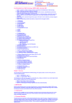
Table of Contents
1.
INTRODUCTION .......................................................................................................... 7
1.1
Requirements ........................................................................................................ 7
1.1.1 The ProDAQ 3020 USB 2.0 VXIbus Slot-0 Interface......................................... 7
1.1.2 The Host Computer ........................................................................................... 7
1.1.3 The VXI Mainframe ........................................................................................... 8
1.1.4 The USB Cable ................................................................................................. 8
2.
INSTALLATION AND CONFIGURATION ................................................................... 9
2.1
Unpacking and Inspection ..................................................................................... 9
2.2
Installing the VISA Library ................................................................................... 10
2.3
Installing the ProDAQ 3020 Interface .................................................................. 12
2.4
Installing the ProDAQ 3020 USB Driver .............................................................. 15
2.5
Configuring the ProDAQ 3020 for the VISA Library ............................................. 17
2.6
Configuring the ProDAQ 3020 Interface Characteristics ..................................... 19
2.6.1 Configuring the VXIbus Access ....................................................................... 20
2.6.2 Configuring the Interrupt Lines ........................................................................ 21
2.6.3 Configuring the Front Panel I/O....................................................................... 21
2.6.4 Firmware Version Checking and Update ......................................................... 23
2.7
Verifying the Installation ...................................................................................... 25
2.7.1 Running the VXIbus Resource Manager ......................................................... 25
2.7.2 The VISA Assistant ......................................................................................... 27
3.
PROGRAMMING VXI DEVICES USING THE PRODAQ 3020 INTERFACE ............. 33
3.1
Connecting to a Device ....................................................................................... 33
3.2
Programming Register-based Devices ................................................................ 34
3.2.1 Accessing Registers ........................................................................................ 34
3.2.2 Moving Blocks of Data .................................................................................... 37
3.3
Programming Message-based Devices ............................................................... 40
3.3.1 Writing and Reading Messages ...................................................................... 40
3.4
Optimising Programs using the ProDAQ 3020 Interface ..................................... 41
3.5
Using VXIbus and Front Panel Trigger Lines....................................................... 42
3.5.1 Using VXIbus Trigger Lines............................................................................. 42
3.5.2 Using Front-Panel Trigger Lines ..................................................................... 43
4.
PROGRAMMING GPIB DEVICES USING THE PRODAQ 3020 INTERFACE .......... 45
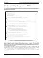
4.1
4.2
5.
Connecting to a Device ....................................................................................... 45
Reading and Writing Messages to/from a GPIB Device ...................................... 46
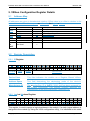
VXIBUS CONFIGURATION REGISTER DETAILS.................................................... 47
5.1
Address Map ....................................................................................................... 47
5.2
Register Description ............................................................................................ 47
5.2.1 ID Register ...................................................................................................... 47
5.2.2 Logical Address Register ................................................................................ 47
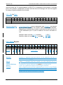
5.2.3 Device Type .................................................................................................... 48
5.2.4 Status Register................................................................................................ 48
5.2.5 Control Register .............................................................................................. 49
Copyright, © 2003 Bustec Production Ltd.
Page 3 of 60
3020-XX-UM
ProDAQ 3020 USB2.0 VXIbus Slot-0 Interface User Manual
5.2.6 MODID Register .............................................................................................. 49
6.
FRONT PANEL CONNECTORS AND SWITCHES ................................................... 51
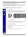
6.1
ProDAQ 3020-AA Front Panel Connectors and Switches ................................... 51
6.1.1 USB Connector ............................................................................................... 51
6.1.2 Clk In/Out Connectors ..................................................................................... 51
6.1.3 Trigger In/Out Connectors ............................................................................... 51
6.1.4 Reset Switch ................................................................................................... 51
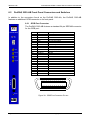
6.2
ProDAQ 3020-AB Front Panel Connectors and Switches ................................... 52
6.2.1 GPIB Port Connector ....................................................................................... 52
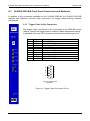
6.3
ProDAQ 3020-BA Front Panel Connectors and Switches ................................... 53
6.3.1 Trigger Chain In/Out Connectors ..................................................................... 53
6.4
ProDAQ 3020-BB Front Panel Connectors and Switches ................................... 54
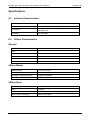
SPECIFICATIONS ............................................................................................................. 55
6.5
6.6
6.7
6.8
6.9
Interface Characteristics ...................................................................................... 55
VXIbus Characteristics ........................................................................................ 55
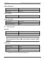
Front Panel I/O .................................................................................................... 56
Power Supply Loading ......................................................................................... 57
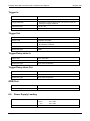
Miscellaneous ...................................................................................................... 58
Page 4 of 60
Copyright, © 2003 Bustec Production Ltd.
ProDAQ 3020 USB 2.0 VXIbus Slot-0 Interface User Manual
3020-XX-UM
Table of Figures
Figure 1 - Selecting the Type of Installation. ...................................................................... 11
Figure 2 - Selecting Components for Installation. .............................................................. 11
Figure 3 - Installing the ProDAQ 3020 into a C-Size Mainframe ........................................ 12
Figure 4 - A-to-B Type USB Cable ..................................................................................... 12
Figure 5 - USB Configurations ........................................................................................... 13
Figure 6 - USB Bus Topology ............................................................................................ 14
Figure 7 - Using the Hardware Wizard. ............................................................................. 15
Figure 8 - Select a Search Location. ................................................................................. 15
Figure 9 - Typical Device Manager Display ....................................................................... 16
Figure 10 - VISA Library Configuration Utility .................................................................... 17
Figure 11 - Adding an Interface ......................................................................................... 18
Figure 12 – Displaying configured Interfaces ..................................................................... 18
Figure 13 - The ProDAQ 3020 Configuration Dialog .......................................................... 19
Figure 14 - New firmware available message. ................................................................... 20
Figure 15 - Configuring the Interrupt Lines ....................................................................... 21
Figure 16 - Configuring the Front Panel I/O ....................................................................... 22
Figure 17 - Firmware Version and Update ......................................................................... 23
Figure 18 - Firmware Update Progress .............................................................................. 24
Figure 19 - Running the VXI Resource Manager ............................................................... 25
Figure 20 - Resource Manager Configuration ................................................................... 26
Figure 21 - The VISA Assistant .......................................................................................... 27
Figure 22 - VISA Assistant Session Window ..................................................................... 27
Figure 23 - Using a template operation .............................................................................. 28
Figure 24 - Using a basic I/O operation ............................................................................. 29
Figure 25 - Memory I/O Operations ................................................................................... 29
Figure 26 - Shared Memory Operations............................................................................. 30
Figure 27 - VXI Specific Operations ................................................................................... 31
Figure 28 - Opening a VISA Session ................................................................................. 33
Figure 29 - Memory-based I/O ........................................................................................... 35
Figure 30 - Register I/O using memory mapping ............................................................... 36
Figure 31 - Moving a Block of Data .................................................................................... 37
Figure 32 - VXIbus transfer types ...................................................................................... 38
Figure 33 - Performing VXIbus Block Transfers ................................................................. 39
Figure 34 - Reading the Device Identification .................................................................... 40
Figure 35 - Sending a Trigger Pulse .................................................................................. 42
Figure 36 - Mapping Trigger Lines ..................................................................................... 44
Figure 37 – Reading and writing messages to/from a GPIB device ................................... 46
Figure 38 - USB Connector Pin-out ................................................................................... 51
Figure 39 - GPIB Port Connector Pin-out........................................................................... 52
Figure 40 - Trigger Chain Connectors Pin-out ................................................................... 53
Copyright, © 2003 Bustec Production Ltd.
Page 5 of 60
3020-XX-UM
ProDAQ 3020 USB2.0 VXIbus Slot-0 Interface User Manual
Page 6 of 60
Copyright, © 2003 Bustec Production Ltd.
ProDAQ 3020 USB 2.0 VXIbus Slot-0 Interface User Manual
3020-XX-UM
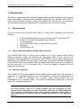
1. Introduction
The USB is a high-speed cable bus that supports data exchange between a host computer
and a wide range of simultaneously accessible peripherals. The ProDAQ 3020 USB 2.0
VXIbus Slot-0 Interface provides a direct link between the USB and the VXI backplane.
This manual describes the implementation, configuration and use of the interface.
1.1
Requirements
To set up and use the ProDAQ 3020 USB 2.0 VXIbus Slot-0 Interface, you need the
following:
A PC compatible computer running Windows 2000® or Windows XP®
A USB 1.1 or USB 2.0 compatible host controller
A VXI mainframe
The ProDAQ 3020 USB 2.0 VXIbus Slot-0 Interface
USB cable
ProDAQ Driver CD
1.1.1 The ProDAQ 3020 USB 2.0 VXIbus Slot-0 Interface
The ProDAQ 3020 USB 2.0 VXIbus Slot-0 Interface is a C-size, register based VXIbus
module providing a direct link between the high-speed USB 2.0 bus and the VXI
backplane. Data packages sent and received via the USB bus will be either translated into
accesses on the VXIbus or can be used to control the configuration and Slot-0 capabilities
of the ProDAQ 3020. The ProDAQ 3020 can automatically detect whether it is installed in
the left most slot of a VXI mainframe (slot “0”) and will enable or disable its Slot-0
capabilities accordingly.
1.1.2 The Host Computer
The ProDAQ 3020 Interface together with the USB controller allows your host computer to
perform as if it is plugged directly into the VXI backplane. It needs to be equipped with a
USB 1.1 or USB 2.0 compatible host controller, either already build-in into the
motherboard or via expansion cards. The drivers and software provided are for Pentium
based PC compatible computers.
Note
The host controller need to be already installed into and recognized by your
system. Bustec Production Inc. does not provide drivers for any USB component
other then the ProDAQ 3020 Interface itself. Please contact the manufacturer of
your motherboard or expansion card for suitable USB drivers for your operating
system.
Copyright, © 2003 Bustec Production Ltd.
Page 7 of 60
3020-XX-UM
ProDAQ 3020 USB2.0 VXIbus Slot-0 Interface User Manual
Note
USB 1.0 compatible host controllers are not supported. USB 1.1 compatible host
controllers are limited to a maximum bus speed of 12 Mb/s. To achieve full
performance with the ProDAQ 3020 Interface, a USB 2.0 host controller is required.
1.1.3 The VXI Mainframe
The ProDAQ 3020 USB 2.0 VXIbus Slot-0 Interface is a single-slot wide, C-size VXI
module, which can reside in any slot of a C-size or D-size VXI mainframe. It will
automatically detect whether it is located in the left most slot of the mainframe (slot “0”)
and will enable or disable its Slot-0 capabilities accordingly, avoiding conflicts with the
backplane and other modules.
Note
Being a C-size module, the ProDAQ 3020 does not provide a P3 connector as used
in D-size mainframes. If used as a slot-0 controller in a D-size mainframe, it cannot
provide the necessary control for instruments using the additional features of the
P3 connector (CLK100, Star Trigger, add. Trigger and Local Bus Lines).
1.1.4 The USB Cable
To connect the ProDAQ 3020 USB2.0 VXIbus Slot-0 Interface to your host computer, use
the USB A-to-B high-/full-speed cable provided. You can connect the ProDAQ 3020 to any
of the USB ports your host computer/expansion board provides. Alternatively, if you are
using a USB hub to connect several USB devices to your computer, you may connect the
ProDAQ 3020 to a port on the hub.
Note
If you are using an additional USB hub to connect the ProDAQ 3020 to your
computer, the hub must be USB 1.1 or 2.0 compatible. To achieve full performance,
the hub must be able to support the high-speed mode as specified by the USB 2.0
standard. In general, using multiple devices connected to the same host controller
port may decrease the performance of your system.
Page 8 of 60
Copyright, © 2003 Bustec Production Ltd.
ProDAQ 3020 USB 2.0 VXIbus Slot-0 Interface User Manual
3020-XX-UM
2. Installation and Configuration
The ProDAQ 3020 USB 2.0 VXIbus Slot-0 Interface is a single slot, C-size VXIbus
instrument and can be installed in any slot of a standard C-size VXI mainframe. To be
Slot-0 controller for the VXIbus system, it must be installed in the leftmost slot of the VXI
mainframe (slot “0“). If it is installed in any other slot of a VXI mainframe, all slot-0
capabilities (MODID, CLK10, etc.) will be automatically turned off.
Note:
The ProDAQ 3020 USB 2.0 VXIbus Slot-0 Interface does not extend the VXI
backplane between mainframes in a multi-mainframe system. This means that
devices sharing the local bus must be installed in the same mainframe.
To install the ProDAQ 3020 USB 2.0 VXIbus Slot-0 Interface and the necessary software
on your system, use the installation sequence as described in this chapter:
2.1
Step 1: Unpacking and Inspection
Step 2: Installing the VISA Library
Step 3: Installing the ProDAQ 3020 Interface
Step 4: Installing the ProDAQ 3020 USB Driver
Unpacking and Inspection
All ProDAQ modules are shipped in an antistatic package to prevent any damage from
electrostatic discharge (ESD). Proper ESD handling procedures must always be used
when packing, unpacking or installing any ProDAQ module, ProDAQ plug-in module or
ProDAQ function card:
Ground yourself via a grounding strap or similar, e.g. by holding to a grounded
object.
Remove the ProDAQ module from its carton, preserving the factory packaging
as much as possible.
Discharge the package by touching it to a grounded object, e.g. a metal part of
your VXIbus chassis, before removing the module from the package.
Inspect the ProDAQ module for any defect or damage. Immediately notify the
carrier if any damage is apparent.
Only remove the module from its antistatic bag if you intend to install it into a VXI
mainframe or similar.
When reshipping the module, use the original packing material whenever possible. The
original shipping carton and the instrument’s plastic foam will provide the necessary
support for safe reshipment. If the original anti-static packing material is unavailable, wrap
the ProDAQ module in anti-static plastic sheeting and use plastic spray foam to surround
and protect the instrument.
Copyright, © 2003 Bustec Production Ltd.
Page 9 of 60
3020-XX-UM
2.2
ProDAQ 3020 USB2.0 VXIbus Slot-0 Interface User Manual
Installing the VISA Library
The VISA library provided by Bustec Production Ltd is used to communicate to the VXI
instruments in mainframes connected via the ProDAQ 3020 USB 2.0 VXIbus Slot-0
Interface to the host PC.
Note
On Microsoft Windows 2000® or Microsoft Windows XP® systems it is
recommended to install the VISA library and the USB driver from an account having
administrator privileges.
To install it on your PC, do the following:
1. Apply power to your PC and boot your operating system. Close all open
applications to allow for a safe installation of the new components.
Do not apply power to the VXI mainframe at this point in time, or, do not
connect the ProDAQ 3020 Interface via the USB bus to your PC !
2. Insert the driver CD provided with the module into your PC CD-ROM drive. If the
autorun feature is turned on, the CD menu will start automatically. If not, select
“Run” from your Start menu and type <drive>:autorun.exe, where <drive>
designates the CD-ROM drive with the driver CD in it.
3. Select “VISA Library for ProDAQ Controller” from the driver section of the CD menu
to start the setup wizard.
Please note: If you have downloaded the Bustec VISA Library from our WEB site,
all files are packed into a single ZIP archive. To start the installation, unpack the
files into a separate directory on your drive and run the executable “setup.exe” from
that location.
4. Select “Next” to review the license agreement for the Bustec VISA library. You will
need to accept the terms of the agreement by selecting “Yes” to be able to install
the Visa library.
5. Select the folder where the wizard will install the components of the VISA library.
Please note that the location chosen will be the top-level directory for a
VXIplug&play standard compliant directory tree, and not a single location for the
library only. If you install VXIplug&play driver on your PC, they will install using the
directory tree created by the VISA installation.
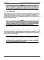
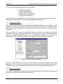
6. Select “Next” to choose the type of setup to perform (see Figure 1). “Typical” will
install the most common components, while “Compact” will only install the absolute
necessary components. To choose which components to install, choose “Custom”.
Page 10 of 60
Copyright, © 2003 Bustec Production Ltd.
ProDAQ 3020 USB 2.0 VXIbus Slot-0 Interface User Manual
3020-XX-UM
Figure 1 - Selecting the Type of Installation.
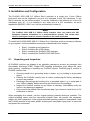
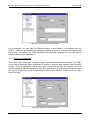
7. If you have chosen “Custom”, selecting “Next” will allow you to select the
components to install (see Figure 2):
VISA Library
The core files (hardware driver, VISA dynamic link library,
config utility, include files) of the installation.
VISA Assistant
An interactive graphical user interface for the VISA library. It
will allow you to use the VISA library without writing your own
application.
Help Files
Help files for the VISA library.
Examples
How to program using the VISA library.
Figure 2 - Selecting Components for Installation.
8. After selecting “Next”, the wizard will install the files and components for the chosen
configuration on your system.
9. Re-start the computer after the installation is complete.
Copyright, © 2003 Bustec Production Ltd.
Page 11 of 60
3020-XX-UM
2.3
ProDAQ 3020 USB2.0 VXIbus Slot-0 Interface User Manual
Installing the ProDAQ 3020 Interface
To prevent damage to the ProDAQ module being installed, it is recommended to remove
the power from the mainframe or to switch it off before installing.
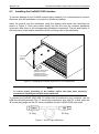
Insert the module into the mainframe using the guiding rails inside the mainframe as
shown in Figure 3. Push the module slowly into the slot until the modules backplane
connectors seat firmly in the corresponding backplane connectors. The top and bottom of
the front panel of the module should touch the mounting rails in the mainframe.
Front panel
mounting
screws
Slide the module into the
mainframe using the
guiding rails until its
connectors plug into the
backplane connectors.
Figure 3 - Installing the ProDAQ 3020 into a C-Size Mainframe
Note:
To ensure proper grounding of the module, tighten the front panel mounting
screws after installing the module in the mainframe.
To connect the ProDAQ 3020 USB 2.0 VXIbus Slot-0 Interface to your computer, use the
USB A-to-B cable provided. The “A” series plug connects to your host PC or hub, while the
“B” series plug plugs into the “B” series receptacle on the ProDAQ 3020 front panel.
“A” Plug
“B” Plug
Figure 4 - A-to-B Type USB Cable
Page 12 of 60
Copyright, © 2003 Bustec Production Ltd.
ProDAQ 3020 USB 2.0 VXIbus Slot-0 Interface User Manual
3020-XX-UM
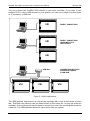
You can connect the ProDAQ 3020 directly to your host controller. If you want to use
multiple 3020 or other USB devices in your system, you can use multiple free host ports
or, if necessary, a USB hub:
VXI
DIRECT CONNECTION
VXI
DIRECT CONNECTION
USING MULTIPLE
HOST PORTS
VXI
USB Hub
VXI
VXI
CONNECTING MULTIPLE
INTERFACES USING
A USB HUB
VXI
Figure 5 - USB Configurations
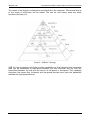
The USB physical interconnect is a tiered star topology with a hub at the center of each
star. Therefore new devices can be added either on the same tier, as long as ports are
available, or one of the ports can be used to connect to a new hub, providing the center for
a new tier. The USB standard allows for up to seven tiers per system.
Copyright, © 2003 Bustec Production Ltd.
Page 13 of 60
3020-XX-UM
ProDAQ 3020 USB2.0 VXIbus Slot-0 Interface User Manual
The center of the first tier is always the controller/hub in the computer. This means that up
to five levels of USB hubs can be added. The last tier (tier seven) does only allow
functions (devices) in it.
Figure 6 - USB Bus Topology
USB 2.0 host controllers and hubs provide capabilities so that full-speed and low-speed
data can be transmitted at high-speed between the host controller and the hub, but
transmitted between the hub and the device at full-speed or low-speed. This capability
minimizes the impact that full-speed and low-speed devices have upon the bandwidth
available for high-speed devices.
Page 14 of 60
Copyright, © 2003 Bustec Production Ltd.
ProDAQ 3020 USB 2.0 VXIbus Slot-0 Interface User Manual
2.4
3020-XX-UM
Installing the ProDAQ 3020 USB Driver
After re-starting your computer, turn on the VXI mainframe and/or connect the ProDAQ
3020 USB 2.0 VXIbus Slot-0 Interface via the USB bus to the PC. Because the USB bus is
hot-plug capable, the system will detect the event and will start to look for a driver for the
new hardware.
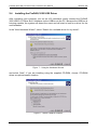
In the “New Hardware Wizard”, select “Search for a suitable driver for my device”:
Figure 7 - Using the Hardware Wizard.
and select “Next”. If you are installing using the supplied CD-ROM, choose “CD-ROM
drives as optional search location:
Figure 8 - Select a Search Location.
Copyright, © 2003 Bustec Production Ltd.
Page 15 of 60
3020-XX-UM
ProDAQ 3020 USB2.0 VXIbus Slot-0 Interface User Manual
If you have downloaded the VISA library from our WEB site, choose “Specify a location”
and specify the location of the directory containing the unpacked installation in the next
step.
Continue through the installation process as directed by the “New Hardware Wizard”. It will
show you the location of the driver files found and allow you to select “Finish” to complete
the installation.
After the driver is installed, the ProDAQ 3020 USB 2.0 VXIbus Slot-0 interface will be
shown in the device manager under “Bustec VXI Devices” once it is connected and
switched on:
Figure 9 - Typical Device Manager Display
Attention:
The VISA configuration utility must be run whenever a new ProDAQ 3020 Interface
is connected to the host PC.
Page 16 of 60
Copyright, © 2003 Bustec Production Ltd.
ProDAQ 3020 USB 2.0 VXIbus Slot-0 Interface User Manual
2.5
3020-XX-UM
Configuring the ProDAQ 3020 for the VISA Library
The VISA library uses interface names and numbers to access available hardware
interfaces. In order to enable the VISA library to use a ProDAQ 3020 interface, which is
connected to a host PC for the first time, a valid interface name and number must be
assigned to this device. The assigned interface name and number will be stored internally
in the configuration for this ProDAQ 3020 interface together with its serial number and will
be used for this device whenever it is connected to this host.
To assign an interface name/number and configure the ProDAQ 3020, connect the USB
interface cable between one USB port of the host PC and the USB port on the ProDAQ
3020 front panel and turn on the VXI mainframe.
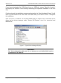
From the VXIplug&play program group created during the installation of the VISA library,
select “VISA Configuration Utility” (“Start” “VXIPNP” “VISA Configuration Utility”).
This will start the configuration tool for the VISA library and attached hardware interfaces.
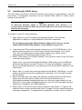
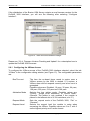
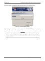
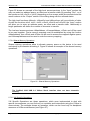
Figure 10 - VISA Library Configuration Utility
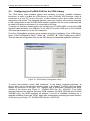
To add a new interface, select “Add Interfaces”. A new dialog “Available Interfaces” is
shown with a list of unconfigured devices found in the system. ProDAQ 3020 interfaces
appear as interfaces of the type “VXI” together with a description containing the serial
number of the device (see Figure 11, ProDAQ 3020 Ser. No. 3201003). If the 3020
detected features the optional on-board GPIB interface (ProDAQ 3020-AB and ProDAQ
3020-BB only), the GPIB interface will appear in the list of available interfaces as a
separate interface of the type “GPIB”, again with a description containing the serial number
of the device (see Figure 11, ProDAQ 3020 Ser.No. 30201018).
Copyright, © 2003 Bustec Production Ltd.
Page 17 of 60
3020-XX-UM
ProDAQ 3020 USB2.0 VXIbus Slot-0 Interface User Manual
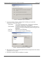
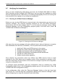
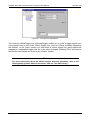
Figure 11 - Adding an Interface
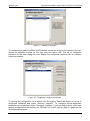
To configure and add a ProDAQ 3020 interface, select the entry for the device in the list,
choose an interface number on the right side and select ‘OK’. The list of configured
interfaces in the main dialog will now display the configured interface with its interface
name and number:
Figure 12 – Displaying configured Interfaces
To remove the configuration for a device from the system, select the device in the list of
configured interfaces and select “Remove Interface”. To configure device-dependent
parameters of an interface, select “Configure Interface”. If you hot-plug a device which was
already configured on this system, the “Refresh List” button can be used to update the list
of configured interfaces.
Page 18 of 60
Copyright, © 2003 Bustec Production Ltd.
ProDAQ 3020 USB 2.0 VXIbus Slot-0 Interface User Manual
2.6
3020-XX-UM
Configuring the ProDAQ 3020 Interface Characteristics
The ProDAQ 3020 USB 2.0 VXIbus Slot-0 interface has a number of characteristics that
can be configured with the configuration utility. The settings are stored together with the
device name/number and the serial number on the host system and applied whenever the
device is connected to the host system and the resource manager is executed.
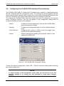
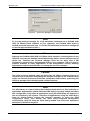
To configure the ProDAQ 3020, select the device you want to configure in the list and
select “Configure Interface”. The four tab panels of the configuration dialog allow to
configure the different parts of the interface:
VXIbus
Interrupt
Front Panel I/O
Version
Configures various parameters used by the ProDAQ 3020
when accessing the VXIbus.
Configures the assignment and use of the VXIbus interrupt
lines.
Configures the routing of VXIbus clock and trigger lines
to/from the front panel connectors.
Allows checking and updating the firmware version of the
attached ProDAQ 3020.
Figure 13 - The ProDAQ 3020 Configuration Dialog
To store the altered configuration, select “OK”. “Cancel” closes the dialog without altering
the stored configuration.
NOTE
To apply changes to the configuration of the 3020, you will need to re-run the
resource manager or to restart your VXI mainframe to make these changes
effective.
.
Copyright, © 2003 Bustec Production Ltd.
Page 19 of 60
3020-XX-UM
ProDAQ 3020 USB2.0 VXIbus Slot-0 Interface User Manual
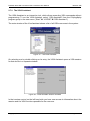
If the distribution of the Bustec VISA library contains a new firmware version for the
ProDAQ 3020 Interface, you will see the following after selecting “Configure
Interface”:
Figure 14 - New firmware available message.
Please see “2.6.4: Firmware Version Checking and Update” for a description how to
update the ProDAQ 3020 firmware.
2.6.1 Configuring the VXIbus Access
To configure the VXIbus access of the ProDAQ 3020 interface selected, select the tab
“VXIbus” in the configuration dialog window (see Figure 13). The configurable parameters
are:
Bus Time-out
Arbitration Mode
Request Mode
Request Level
Page 20 of 60
The time the on-board times needs to expire once a
VXIbus access by the 3020 is started. If it expires, a
VXIbus slave did not respond correctly and a bus error is
generated.
Possible values are: Disabled, 16 µsec, 32 µsec, 64 µsec,
128 µsec, 256 µsec, 512 µsec and 1024 µsec.
Selects the bus arbiter mode. Possible values are:
“Priority”, “Single Level Arbitration” or “Round Robin”.
(Remark: The arbiter is only enabled if the module is
placed in the leftmost slot of a VXI mainframe, slot “0”).
Sets the request mode of the ProDAQ 3020, “Fair” or
“Demand”.
Selects the request level the module is using when
accessing the VXIbus. Possible values are 3 to 0, with 3
as the highest priority and 0 as the lowest.
Copyright, © 2003 Bustec Production Ltd.
ProDAQ 3020 USB 2.0 VXIbus Slot-0 Interface User Manual
Release Mode
3020-XX-UM
Selects the release mode: “RWD” (release when done) or
“ROR” (release on request).
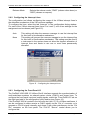
2.6.2 Configuring the Interrupt Lines
The configuration tool allows configuring the usage of the VXIbus interrupt lines in
the allocation mechanism of the VXI resource manager.
To configure the lines, select the tab “Interrupt” in the configuration dialog window.
For each of the VXIbus interrupt lines (Level 1 to Level 7) one of two settings for the
assignment can be chosen (see Figure 15):
Auto
None
This setting will allow the resource manager to use the interrupt line
for this level in his allocation mechanism.
This setting will prevent the resource manage to use the interrupt line
for this level in his allocation mechanism. This setting must be used if
a instrument in the system does not allow the dynamic allocation of
interrupt lines and wants to use one or more lines permanently
allocated.
Figure 15 - Configuring the Interrupt Lines
2.6.3 Configuring the Front Panel I/O
The ProDAQ 3020 USB 2.0 VXIbus Slot-0 Interface supports the synchronization of
multi-mainframe systems via shared system clocks (CLK10) and trigger lines. To
configure the front panel input and output signals, select the “Front Panel I/O” tab on
the right hand side of the configuration utility window (see Figure 16).
If the ProDAQ 3020 is located in the left most slot (slot “0”) of a VXIbus mainframe, it
can be configured to either receive a CLK10 signal via the “Clk In” connector or to
generate a CLK10 signal internally and share it with other mainframes via the “Clk
Out” connector on the front panel. The “CLK10” “Source” control allows you to
configure this:
Copyright, © 2003 Bustec Production Ltd.
Page 21 of 60
3020-XX-UM
ProDAQ 3020 USB2.0 VXIbus Slot-0 Interface User Manual
Internal
The ProDAQ 3020 uses the internal clock generator to generate
the CLK10 clock signal for the VXIbus and additionally makes the
clock signal available via the front panel “Clk Out” connector.
External
The internal clock generator is disabled and the ProDAQ 3020
uses the clock signal from the “Clk In” connector to generate the
VXIbus CLK10 clock signal.
If the module is located in any other slot in a VXIbus system, the CLK10 signal
supplied by the VXIbus is used.
Figure 16 - Configuring the Front Panel I/O
The VXIbus trigger lines TTL0 to TTL7 and ECL0/ECL1 can be mapped to the front panel
“Trig In” and “Trig Out” connectors (see also 3.5.2: Using Front-Panel Trigger Lines). The
ProDAQ 3020-AB supports in addition to build a daisy chain to forward all or some TTL
trigger lines from one mainframe to another.
The “Active Edge” control in the “Input Trigger” area can be used to select the active edge
for the trigger detection on the “Trig In” connector:
Rising
Falling
A rising edge detected on the front panel “Trig In” connector will assert
the VXIbus trigger lines mapped to the input, a subsequent falling
edge will de-assert the trigger lines.
A falling edge detected on the front panel “Trig In” connector will
assert the VXIbus trigger lines mapped to the input, a subsequent
rising edge will de-assert the trigger lines.
The “Active Level” control in the “Output Trigger” area can be used to select the level
mapping of the VXIbus trigger lines to the level of the “Trig Out” signal:
Page 22 of 60
Copyright, © 2003 Bustec Production Ltd.
ProDAQ 3020 USB 2.0 VXIbus Slot-0 Interface User Manual
3020-XX-UM
Low
The output signal is active low. Asserting one of the mapped trigger
lines on the VXIbus will cause the signal on the “Trig Out” connector
to change its state from the default high level (1) to the low level (0).
High
The output signal is active high. Asserting one of the mapped trigger
lines on the VXIbus will cause the signal on the “Trig Out” connector
to change its state from the default low level (0) to the high level (1).
The actual mapping of the “Trig In” signal to one or many of the VXIbus trigger lines and
the mapping of the VXIbus trigger line or lines to the “Trig Out” signal is done using VISA
functions (see 3.5.2: Using Front-Panel Trigger Lines).
The ProDAQ 3020 version “-AB” features two additional connectors on the front panel (see
6.3.1: Trigger Chain In/Out Connectors). They allow to daisy chain the VXIbus TTL trigger
signals from one mainframe in a multi-mainframe system to another. The eight controls
“VXI TTL 0” to VXI TTL 7” allow to selectively enable the VXIbus TTL trigger lines to be
received via the front panel “Trig. Daisy Chain In” connector and forwarded by the front
panel “Trig. Daisy Chain Out” connector.
2.6.4 Firmware Version Checking and Update
Selecting the “Version” tab shows the firmware version of the firmware installed on the
ProDAQ 3020 interface as well as the one available with the current distribution of the
VISA library and tools:
Figure 17 - Firmware Version and Update
To update the firmware installed on the ProDAQ 3020 selected, press the “Update
Firmware” button in the lower right half of the dialog.
The update process will download and replace the firmware stored in a FLASH memory on
the ProDAQ 3020 Interface. Please make sure that the process is not interrupted,
otherwise the ProDAQ 3020 may become unusable and has to be returned to the factory
for repair. It is recommended to close all other applications before starting the update.
Copyright, © 2003 Bustec Production Ltd.
Page 23 of 60
3020-XX-UM
ProDAQ 3020 USB2.0 VXIbus Slot-0 Interface User Manual
During the update, a progress bar will show the status of the update process:
Figure 18 - Firmware Update Progress
After finishing the update, you need to cold start the ProDAQ 3020 by power cycling the
VXIbus mainframe to make the change effective.
Warning
Do not stop the configuration utility or power cycle the VXI mainframe during the
firmware update. Otherwise the ProDAQ 3020 USB 2.0 VXIbus Slot-0 Interface may
become unusable.
Page 24 of 60
Copyright, © 2003 Bustec Production Ltd.
ProDAQ 3020 USB 2.0 VXIbus Slot-0 Interface User Manual
2.7
3020-XX-UM
Verifying the Installation
Once you have installed the VISA library and tools, the ProDAQ 3020 USB 2.0 VXIbus
Slot-0 Interface and the ProDAQ 3020 USB driver, you can verify the installation by using
the tools supplied with the VISA library, by installing VXIplug&play drivers and running the
instruments soft front panels or by running your application.
2.7.1 Running the VXIbus Resource Manager
Before you can use the VISA library to communicate to the instruments, you must run the
resource manager. The resource manager searches for VXI and GPIB instruments
connected to your PC and configure them. To run the resource manager, select “VXIbus
Resource Manager” from the VXIplug&play program group in the start menu (“Start”
“VXIPNP” ”VXI Resource Manager”).
Figure 19 - Running the VXI Resource Manager
After start, the resource manager will wait a defined time to allow all devices to complete
their initialization and self-test (if available). Then he performs the following functions:
1.
2.
3.
4.
5.
6.
Identify all VXIbus and GPIB devices in the system.
Manage the system self-test and diagnostic sequence.
Configure the system’s A24 and A32 address maps.
Configure the system’s Commander/Servant hierarchies.
Allocate the VXIbus IRQ lines.
Initiate normal system operation.
Once finished, the information about the VXIbus and GPIB devices found is made
available for the VISA library and a readable version of this information is saved to a file.
Both the initial delay and the location of the resource manager output file are configurable
using the configuration utility.
To configure these parameters, start the configuration utility by selecting the “VISA
Configuration Utility” entry in the VXIplug&play program group in the start menu (“Start”
“VXIPNP” ”VISA Configuration Utility”).
In the configuration utility, select the “Resource Manager” button on the right hand side
(see Figure 10). This will show the configuration dialog for the resource manager, which
allows configuring the output file destination and initial delay.
Copyright, © 2003 Bustec Production Ltd.
Page 25 of 60
3020-XX-UM
ProDAQ 3020 USB2.0 VXIbus Slot-0 Interface User Manual
Figure 20 - Resource Manager Configuration
Note
To run the resource manager for a VXI mainframe connected via a ProDAQ 3020
USB 2.0 VXIbus Slot-0 Interface to your computer, the ProDAQ 3020 must be
located in the left most slot (slot “0”) of the VXI mainframe and must be configured
to use the logical address 0 (00hex).
Note
Although the ProDAQ 3020 USB 2.0 VXIbus Slot-0 Interface is hot-plug able via the
USB bus, the resource manager cannot dynamically add or remove devices from its
device list. Therefore the resource manager must be run every time a VXI
mainframe is connected or disconnected to/from your computer. There is also no
protocol available to notify applications of the configuration change. Running
applications must be restarted after re-running the resource manager.
Caution
The initial resource manager delay as defined by the VXIbus standard must be in
minimum five (5) seconds. Configuring the resource manager to use a shorter delay
might not allow all devices to finish their initialization and self-test, preventing the
resource manager from identifying and configuring them.
Note
The VISA library is a shared library that initializes itself when it is first loaded by an
application. Applications started while the VISA library is already loaded just share
this configuration. Only when all applications using the VISA library are stopped, it
will be unloaded by the system. Therefore all applications using the VISA library
must be closed before running the resource manager or using the VISA
configuration utility. Take special care while using integrated development
environments, they will keep the VISA library loaded even when the application
developed in them was stopped.
Page 26 of 60
Copyright, © 2003 Bustec Production Ltd.
ProDAQ 3020 USB 2.0 VXIbus Slot-0 Interface User Manual
3020-XX-UM
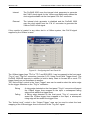
2.7.2 The VISA Assistant
The VISA Assistant is an interactive tool, which allows executing VISA commands without
programming. To run the VISA Assistant, select “VISA Assistant” from the VXIplug&play
program group in the start menu (“Start” “VXIPNP” ”VISA Assistant”).
The main window of the Visa Assistant shows a list of all VISA resources in the system:
Figure 21 - The VISA Assistant
On selecting one by double-clicking on its entry, the VISA Assistant opens a VISA session
for that device in a separate window:
Figure 22 - VISA Assistant Session Window
In the treeview control on the left hand side you have now access to information about the
session and the VISA functions possible for the resource.
Copyright, © 2003 Bustec Production Ltd.
Page 27 of 60
3020-XX-UM
ProDAQ 3020 USB2.0 VXIbus Slot-0 Interface User Manual
The functions available are divided into five groups:
Template Operations
Basic I/O Operations
Memory I/O Operations
Shared Memory Operations
VXI Specific Operations
Not all operations are available for all types of devices, so depending on the device type,
the treeview control might not list all the possibilities discussed here.
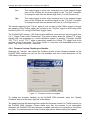
2.7.2.1 Template Operations
The VISA standard implements a template of standard services for a resource. The
functions in this group provide access to those services. The services available include
attribute operations, asynchronous operation control, resource access control and event
operations.
As an example, the function viGetAttribute allows to retrieve the values for attributes
defined for a resource. Selecting the function in the treeview control on the left hand side
(click on “Template Operations”, then on “viGetAttribute”) allows you to control the
parameters for the function in a dialog on the right hand side of the session window:
Figure 23 - Using a template operation
Select one of the attributes to retrieve in the “Attribute” control in the “Input” section and
press “Run”. The “Output” section will show the current value of the attribute in the control
“Attribute state”, if the operation was successful, and the returned status of the function.
2.7.2.2 Basic I/O Operations
The basic I/O operations will allow the user to send commands to a device and read back
its answer, to trigger the device or read its status.
Page 28 of 60
Copyright, © 2003 Bustec Production Ltd.
ProDAQ 3020 USB 2.0 VXIbus Slot-0 Interface User Manual
3020-XX-UM
Figure 24 - Using a basic I/O operation
As an example, you can use the viRead function to read data or a message from the
device. To do so, just specify the maximum number of bytes to read from the device and
press “Run”. As before, the VISA Assistant will show the message read as well as the
returned status of the operation.
2.7.2.3 Memory I/O Operations
The memory I/O operations consist of High- and Low-Level Access services. The HighLevel Access Services allow register-level access to devices that support direct memory
access. They encapsulate most of the code required to perform the access, such as
window mapping, address translation and error checking. The Low-Level Access Services
are similar in purpose, but are implemented without the software overhead of the HighLevel Services.
Figure 25 - Memory I/O Operations
Copyright, © 2003 Bustec Production Ltd.
Page 29 of 60
3020-XX-UM
ProDAQ 3020 USB2.0 VXIbus Slot-0 Interface User Manual
Figure 25 shows an example of the high-level access services. In the “Input” section the
user can select an address space, an offset and a transfer width. By pressing “Run”, on of
the functions viIn8, viIn16 or viIn32 (depending on the access width) are executed and the
result is shown in the “Output” section of the dialog along with the returned status.
The high-level functions viMoveIn, viMoveOut and viMoveAsync will move blocks of data.
As with the functions viIn8, vIn16, viIn32, viOut8, viOut16 and viOut32, the “Input” section
will allow you to enter an address space, an offset and a transfer width. Additionally a
length parameter will define the number of elements to transfer.
The low-level access services viMapAddress, viUnmapAddress, viPeek and viPoke need
to be used together. First a memory mapping must be established by using the function
viMapAddress, then viPeek and viPoke can be used to access the mapped register space,
and viUnmapAddress must be used to undo the memory mapping.
2.7.2.4 Shared Memory Operations
Shared memory operations allow to allocate memory space on the device to be used
exclusively by the session allocating it. Figure 26 shows an example of the shared memory
operations.
Figure 26 - Shared Memory Operations
Note
The ProDAQ 3020 USB 2.0 VXIbus Slot-0 Interface does not have shareable
memory.
2.7.2.5 VXI Specific Operations
VXI Specific Operations are those operations, which were implemented to deal with
special circumstances you can find only on controller and instruments using the VXIbus to
communicate. The example shows an operation, which can be found only for backplane
resources of VXIbus mainframes (see Figure 27).
Page 30 of 60
Copyright, © 2003 Bustec Production Ltd.
ProDAQ 3020 USB 2.0 VXIbus Slot-0 Interface User Manual
3020-XX-UM
Figure 27 - VXI Specific Operations
The functions viMapTrigger and viUnmapTrigger enable you to route a trigger signal from
a front panel input to one of the VXIbus trigger lines (only for VXIbus controller supporting
this feature). In the “Input” section you can select a source trigger line, which should be
mapped to a destination trigger line. As in the other examples, pressing “Run” will execute
the function and display the result in the “Output” section.
Note
For more information about the VISA functions and their parameter, refer to the
VXIplug&play Systems Alliance document “VPP-4.3: The VISA Library”.
Copyright, © 2003 Bustec Production Ltd.
Page 31 of 60
3020-XX-UM
Page 32 of 60
ProDAQ 3020 USB2.0 VXIbus Slot-0 Interface User Manual
Copyright, © 2003 Bustec Production Ltd.
ProDAQ 3020 USB 2.0 VXIbus Slot-0 Interface User Manual
3020-XX-UM
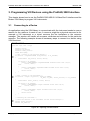
3. Programming VXI Devices using the ProDAQ 3020 Interface
This chapter shows how to use the ProDAQ 3020 USB 2.0 VXIbus Slot-0 Interface and the
Bustec VISA library to program VXI instruments.
3.1
Connecting to a Device
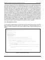
An application using the VISA library to communicate with the instrument needs to open a
session for the resource it wants to use. A resource might be a physical resource as for
example a VXI instrument or a virtual resource like the backplane or the resource
manager. The session will handle all accesses, attributes and services for the particular
resource. The following example shows all necessary steps to connect to a device using
VISA functions:
#include <visa.h>
main (int argc, char **argv)
{
ViStatus status;
ViSession rm_session;
ViSession instr_session;
ViChar descr[256];
/* open a session to the resource manager */
if ((status = viOpenDefaultRM (&rm_session)) != VI_SUCCESS)
{
viStatusDesc (rm_session, status, descr);
if (status > VI_SUCCESS)
printf (“VISA WARNING: viOpenDefaultRM returned status %08x (%s)\n”,
status, descr);
else
{
printf (“VISA ERROR: viOpenDefaultRM returned status %08x (%s)\n”,
status, descr);
return status;
}
}
/* open a session to the instrument */
if ((status = viOpen (rm_session, “VXI0::2::INSTR”,
VI_NULL, VI_NULL, &instr_session)) != VI_SUCCESS)
{
viStatusDesc (instr_session, status, descr);
if (status > VI_SUCCESS)
printf (“VISA WARNING: viOpen returned status %08x (%s)\n”,
status, descr);
else
{
printf (“VISA ERROR: viOpen returned status %08x (%s)\n”,
status, descr)
return status;
}
}
/* accessing the instrument */
/* close the sessions to the instrument and the resource manager */
viClose (instr_session);
viClose (rm_session);
}
Figure 28 - Opening a VISA Session
Copyright, © 2003 Bustec Production Ltd.
Page 33 of 60
3020-XX-UM
ProDAQ 3020 USB2.0 VXIbus Slot-0 Interface User Manual
The first step in a program, which uses the VISA library, is always to open a session to the
default resource manager (). It provides connectivity to all VISA resources registered
with it and gives applications control and access to individual resources.
The next step is to open a session to the instrument or multiple sessions to multiple
instruments (). The resource name used is a combination of interface type and number,
logical address of the VXI device, and a device type:
VXI 0 :: 2 :: INSTR
Interface Type
Interface Number
Device Type
Logical Address
The interface type for the ProDAQ 3020 USB2.0 VXIbus Interface is always “VXI”. The
interface number is the number, which was assigned to the particular 3020 by using the
VISA configuration utility (see 2.5Configuring the ProDAQ 3020 for the VISA Library). The
logical address of a VXI device is defined either statically by setting its logical address
switch, or dynamically during runtime by the resource manager. If the resource manager
assigned the address dynamically, the actual assignment can be found in the output file of
the resource manager (see 2.7.1 - Running the VXIbus Resource Manager). The device
type for VXI instruments is always “INSTR”.
Note
When running the above example, please make sure that the logical address used
in it matches the logical address setting of the instrument you want to connect to.
Note
Before you can use the above example to connect to your device, you must run the
VXI Resource Manager (see 2.7.1: Running the VXIbus Resource Manager).
3.2
Programming Register-based Devices
Register-based devices are devices implementing a set of registers in A16 and often in
A24 or A32. Programming register-based devices is done by reading and writing these
registers to change their contents, either by bit, in groups of bits or in whole.
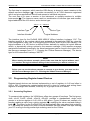
3.2.1 Accessing Registers
To access single registers, the VISA library offers two groups of functions. The first group,
viIn8, viIn16, viIn32, viOut8, viOut16, viOut32, provides a standardized, single word
access to a device register in A16, A24 or A32 space. Figure 29 shows an example of a
function reading a value from a device register (), modifying the value read and writing it
back (). The driver for the ProDAQ 3020 will automatically take care about byte ordering,
i.e. it will swap the words to be read or written between the little-endian host byte ordering
your PC is using to the big-endian byte ordering used on the VXIbus.
Page 34 of 60
Copyright, © 2003 Bustec Production Ltd.
ProDAQ 3020 USB 2.0 VXIbus Slot-0 Interface User Manual
3020-XX-UM
ViStatus function rmw_register (ViSession instr_session, ViBusAddress offset, ViUInt16 mod)
{
ViStatus status;
ViChar descr[256];
ViUInt16 value;
if ((status = viIn16 (instr_session, VI_A16_SPACE, offset, &value) != VI_SUCCESS)
{
viStatusDesc (instr_session, status, descr);
if (status
printf
else
{
printf
return
}
> VI_SUCCESS)
(“VISA WARNING: viIn16 returned status %08x (%s)\n”, status, descr);
(“VISA ERROR: viIn16 returned status %08x (%s)\n”, status, descr);
status;
}
value = value | mod;
if ((status = viOut16 (instr_session, VI_A16_SPACE, offset, value) != VI_SUCCESS)
{
viStatusDesc (instr_session, status, descr);
if (status
printf
else
{
printf
return
}
> VI_SUCCESS)
(“VISA WARNING: viOut16 returned status %08x (%s)\n”, status, descr);
(“VISA ERROR: viOut16 returned status %08x (%s)\n”, status, descr);
status;
}
return VI_SUCCESS;
}
Figure 29 - Memory-based I/O
The second group of functions is intended to map a register range into the memory of the
host and accessing it directly. Because this ability is architecture and system dependent,
the VISA standard foresees an attribute, which allows determining whether the range
could be physically mapped or the system architecture does not allow it. Depending on the
value of the attribute VI_ATTR_WIN_ACCESS, the range mapped can be directly
accessed (e.g. by using a C-style pointer), or the functions viPeek8, viPeek16, viPeek32,
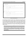
viPoke8, viPoke16 and viPoke32 must be used to access registers in the mapped range.
Figure 30 shows the same function as in Figure 29, this time implemented with memory
mapping functions.
Note
The ProDAQ 3020 USB 2.0 VXIbus Slot-0 interface does not support direct memory
mapping. Any access to the VXIbus is forwarded via packets on the USB bus from
the host to the interface, executed and the result send back via a second packet
from the interface to the host. Therefore the functions viPeek8, viPeek16, viPeek32,
viPoke8, viPoke16 and viPoke32 must be used when mapping a memory range
using viMapAddress.
Copyright, © 2003 Bustec Production Ltd.
Page 35 of 60
3020-XX-UM
ProDAQ 3020 USB2.0 VXIbus Slot-0 Interface User Manual
ViStatus function rmw_register (ViSession instr_session, ViBusAddress offset, ViUInt16 mod)
{
ViStatus status;
ViChar descr[256];
ViAddr address;
ViUInt16 win_access;
ViUInt16 value;
(instr_session, VI_A32_SPACE, offset,
if ((status = viMapAddress
sizeof (ViUInt16), VI_FALSE, (ViAddr) 0, &address)) != VI_SUCCESS)
{
viStatusDesc (instr_session, status, descr);
if (status > VI_SUCCESS)
printf (“VISA WARNING: viMapAddress returned status %08x (%s)\n”,
status, descr);
else
{
printf (“VISA ERROR: viMapAddress returned status %08x (%s)\n”,
status, descr);
return status;
}
}
(instr_session,
if ((status = viGetAttributeVI_ATTR_WIN_ACCESS,
&win_access)) != VI_SUCCESS)
{
viStatusDesc (instr_session, status, descr);
if (status > VI_SUCCESS)
printf (“VISA WARNING: viGetAttribute returned status %08x (%s)\n”,
status, descr);
else
{
printf (“VISA ERROR: viGetAttribute returned status %08x (%s)\n”,
status, descr);
return status;
}
}
if (win_access == VI_DEREF_ADDR)
{
/* allowed to use pointer or similar */
value = *((ViUInt16 *) address);
value = value | mod;
*((ViUInt16 *) address) = value;
}
else if (win_access == VI_USE_OPERS)
{
/* use functions to access memory */
viPeek16 (instr_session, address, &value);
value = value | mod;
viPoke16 (instr_session, address, value);
}
if{ ((status = viUnmapAddress (instr_session) != VI_SUCCESS)
viStatusDesc (instr_session, status, descr);
if (status > VI_SUCCESS)
printf (“VISA WARNING: viUnmapAddress returned status %08x (%s)\n”,
status, descr);
else
{
printf (“VISA ERROR: viUnmapAddress returned status %08x (%s)\n”,
status, descr);
return status;
}
}
return VI_SUCCESS;
}
Figure 30 - Register I/O using memory mapping
Page 36 of 60
Copyright, © 2003 Bustec Production Ltd.
ProDAQ 3020 USB 2.0 VXIbus Slot-0 Interface User Manual
3020-XX-UM
In the above example, the function viMapAddress is used to map a register range starting
with offset and extending over the size of the register into the memory of the host (). If
this is successful, the attribute “VI_ATTR_WIN_ACCESS” is checked to see whether the
controller was able to map the address range physically into the memory space of the
controller, or whether the mapping was done only logically (). If the mapping was done
physically, the application is allowed to use the address, the register range is mapped to,
as if it is accessing its own memory. So for example C-style pointers may be used to
change the register value (). If the mapping was done only logically, the application need
to use the functions viPeek and viPoke provided by the VISA library to access the mapped
register range (). The VISA library will use the stored values for the mapped offset and
range to calculate the physical address and execute a single access in the same way as
internally done for the high-level functions. The function viUnmapAddress must be used to
undo the mapping of the register range (). Only one mapping per session is allowed by
the VISA standard. Please not that the functions viPeek and viPoke will work in both cases
(VI_ATTR_WIN_ACCESS equal to VI_DEREF_ADDR or equal to VI_USE_OPERS), but
will introduce a slightly higher overhead then using direct access if possible.
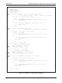
3.2.2 Moving Blocks of Data
To move blocks of data between an instruments memory and the host memory, the VISA
library implements the functions viMoveIn and viMoveOut for different transfer sizes. In
addition a number of attributes can be used to define the type of transfer performed on the
VXIbus.
#include <visa.h>
/* buffer used to store data from the instrument */
ViUInt16 data[1024];
main (int argc, char **argv)
{
ViStatus status;
ViSession rm_session;
ViSession instr_session;
ViChar descr[256];
ViUInt16 value;
/* open a session to the resource manager and instrument
* as shown in Figure 28 - Opening a VISA Session (not shown here) */
. . . .
/* now move a block of 16-bit data from the instrument to the buffer */
if ((status = viMoveIn16 (instr_session,
VI_A32_SPACE, MEM_START, 1024, data) != VI_SUCCESS)
{
viStatusDesc (instr_session, status, descr);
if (status
printf
else
{
printf
return
}
> VI_SUCCESS)
(“VISA WARNING: viMoveIn16 returned status %08x (%s)\n”, status, descr);
(“VISA ERROR: viMoveIn16 returned status %08x (%s)\n”, status, descr);
status;
}
/* close the sessions as shown in Figure 28 - Opening a VISA Session */
. . . . .
}
Figure 31 - Moving a Block of Data
Copyright, © 2003 Bustec Production Ltd.
Page 37 of 60
3020-XX-UM
ProDAQ 3020 USB2.0 VXIbus Slot-0 Interface User Manual
For each move, one or several packets of data are moved over the VXIbus to the ProDAQ
3020 and via the USB bus between the ProDAQ 3020 and the host computer. The transfer
between the ProDAQ 3020 and the host computer is always done in blocks. The size and
the speed, with which the blocks are transferred via the USB bus depends on the type of
USB port used. USB 1.1 allows for a maximum block size of 64 Bytes at 12 Mb/s, while
USB 2.0 allows for maximum block size of 512 Bytes at 480 Mb/s.
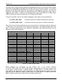
The type of transfer used on the VXIbus depends on the value of several attributes:
VI_ATTR_SRC_PRIV
for data moved from a VXIbus instrument to the host
VI_ATTR_DEST_PRIV
for data moved from the host to a VXIbus instrument
Only if the value of those attributes are set correctly prior to moving the data via viMoveIn
or viMoveOut, a block transfer on the VXIbus will take place. The following table shows the
type of transfers performed by the viMoveIn, viMoveOut and viMove functions for the
different values of the attributes:
Settings
Attribute
VI_DATA_PRIV
VI_DATA_NPRIV
VI_PROG_PRIV
VI_PROG_NPRIV
VI_BLCK_PRIV
VI_BLCK_NPRIV
VI_D64_PRIV
VI_D64_NPRIV
Address Space
VI_A16_SPACE
VI_A24_SPACE
VI_A32_SPACE
VI_A16_SPACE
VI_A24_SPACE
VI_A32_SPACE
VI_A16_SPACE
VI_A24_SPACE
VI_A32_SPACE
VI_A16_SPACE
VI_A24_SPACE
VI_A32_SPACE
VI_A16_SPACE
VI_A24_SPACE
VI_A32_SPACE
VI_A16_SPACE
VI_A24_SPACE
VI_A32_SPACE
VI_A16_SPACE
VI_A24_SPACE
VI_A32_SPACE
VI_A16_SPACE
VI_A24_SPACE
VI_A32_SPACE
Resulting Transfer
Privilege
Data/Program
Supervisory Supervisory Data
Supervisory Data
Non-priv.
Non-priv.
Data
Non-priv.
Data
Supervisory Supervisory Program
Supervisory Program
Non-priv.
Non-priv.
Program
Non-priv.
Program
Supervisory Supervisory Supervisory Non-priv.
Non-priv.
Non-priv.
Supervisory Supervisory Supervisory Non-priv.
Non-priv.
Non-priv.
-
Block Transfer
BLT
BLT
BLT
BLT
MBLT
MBLT
MBLT
MBLT
AM(hex)
2D
3D
0D
29
39
09
2D
3E
0E
29
3A
0A
2D
3F
0F
29
3B
0B
2D
3C
0C
29
38
08
Figure 32 - VXIbus transfer types
Block transfers are performed on the VXIbus only if the correct attribute
(VI_ATTR_SRC_PRIV or VI_ATTR_DEST_PRIV, depending on the direction) is set to one
of the types VI_BLCK_PRIV, VI_BLCK_NPRIV, VI_D64_PRIV or VI_D64_NPRIV. The
data width of the performed transfer depends on the viMoveXX function used, except for
the case that the attribute is set to VI_D64_PRIV or VI_D64_NPRIV, in which case a D64
MBLT transfer is performed (viMoveIn32 and viMoveOut32 only).
Page 38 of 60
Copyright, © 2003 Bustec Production Ltd.
ProDAQ 3020 USB 2.0 VXIbus Slot-0 Interface User Manual
3020-XX-UM
#include <visa.h>
ViUInt16 data[1024];
/* buffer used to store data */
main (int argc, char **argv)
{
ViStatus status;
ViSession rm_session;
ViSession instr_session;
ViChar descr[256];
ViUInt16 value;
/* open a session to the resource manager and instrument
* as shown in Figure 28 - Opening a VISA Session (not shown here) */
/********************************************************************************/
/* Perform a 16-bit wide block transfer from a VXIbus instrument to the host
*/
/********************************************************************************/
/* set the correct attribute – VI_ATTR_SRC_PRIV for moving data IN */
if ((status = viSetAttribute (instr_session,
VI_ATTR_SRC_PRIV, VI_BLK_PRIV)) != VI_SUCCESS)
{
/* handle errors or warnings (not shown here) */
}
/* now move a block of 16-bit data from the instrument to the buffer */
if ((status = viMoveIn16 (instr_session,
VI_A32_SPACE, MEM_START, 1024, data) != VI_SUCCESS)
{
/* handle errors or warnings (not shown here) */
}
/********************************************************************************/
/* Perform a 32-bit wide block transfer from the host to a VXIbus instrument
*/
/********************************************************************************/
/* set the correct attribute – VI_ATTR_DEST_PRIV for moving data OUT */
if ((status = viSetAttribute (instr_session,
VI_ATTR_DEST_PRIV, VI_BLK_PRIV)) != VI_SUCCESS)
{
/* handle errors or warnings (not shown here) */
}
/* now move a block of 32-bit data from the instrument to the buffer */
if ((status = viMoveOut32 (instr_session,
VI_A32_SPACE, MEM_START, 1024, data) != VI_SUCCESS)
{
/* handle errors or warnings (not shown here) */
}
/********************************************************************************/
/* Perform a 64-bit wide block transfer from the host to a VXIbus instrument
*/
/********************************************************************************/
/* set the correct attribute – VI_ATTR_DEST_PRIV for moving data OUT */
if ((status = viSetAttribute (instr_session,
VI_ATTR_DEST_PRIV, VI_D64_PRIV)) != VI_SUCCESS)
{
/* handle errors or warnings (not shown here) */
}
/* now move a block of 64-bit data from the instrument to the buffer */
if ((status = viMoveOut32 (instr_session,
VI_A32_SPACE, MEM_START, 1024, data) != VI_SUCCESS)
{
/* handle errors or warnings (not shown here) */
}
/* close the sessions as shown in Figure 28 - Opening a VISA Session */
}
Figure 33 - Performing VXIbus Block Transfers
Copyright, © 2003 Bustec Production Ltd.
Page 39 of 60
3020-XX-UM
3.3
ProDAQ 3020 USB2.0 VXIbus Slot-0 Interface User Manual
Programming Message-based Devices
Message-based VXIbus devices implement the word serial protocol to communicate with
the application. Programming is done by sending ASCII messages to the device and
reading its answer.
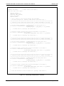
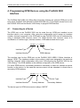
3.3.1 Writing and Reading Messages
The basic functions to write and read messages to/from devices are the two functions
viRead and viWrite. They implement the word serial protocol for message based devices,
but they do so on a very basic level. The user needs to build his message and use viWrite
to send it to the device. Then he uses viRead to receive the message sent back. The
message received might consists of strings, numbers and formatting characters and he will
need to interpret this message. To avoid some of these steps, a couple of higher level
functions were implemented in the VISA.
The following examples shows how to use the functions viPrintf and viScanf to read the
identification of a device:
#include <visa.h>
main (int argc, char **argv)
{
ViStatus status;
ViSession rm_session;
ViSession instr_session;
ViChar descr[256];
/* open a session to the resource manager */
if ((status = viOpenDefaultRM (&rm_session)) != VI_SUCCESS)
{
/* error handling as shown in the previous examples !*/
}
/* open a session to the instrument */
if ((status = viOpen (rm_session, “VXI0::2::INSTR”,
VI_NULL, VI_NULL, &instr_session)) != VI_SUCCESS)
{
/* error handling as shown in the previous examples !*/
}
/* reset the device */
if ((status = viPrintf (vi, “*RST\n”)) != VI_SUCCESS)
{
/* error handling as shown in the previous examples !*/
}
/* ask the device for its identification */
if ((status = viPrintf (vi, “*IDN?\n”)) != VI_SUCCESS)
{
/* error handling as shown in the previous examples !*/
}
/* read the identification sent back */
if ((status = viScanf (vi, “%256t”, descr)) != VI_SUCCESS)
{
/* error handling as shown in the previous examples !*/
}
printf (“Device Identification: %s\n”, descr);
/* close the sessions to the instrument and the resource manager */
viClose (instr_session);
viClose (rm_session);
}
Figure 34 - Reading the Device Identification
Page 40 of 60
Copyright, © 2003 Bustec Production Ltd.
ProDAQ 3020 USB 2.0 VXIbus Slot-0 Interface User Manual
3020-XX-UM
The functions ViPrintf and viScanf use a C-style formatting string to format and scan
messages send to and read from the device, freeing the user from the separate steps
necessary to do so, if using the lower level function viWrite and viRead. Furthermore the
functions implement an extended set of formatting styles specially shaped towards
instrument communication.
In the above example the function viPrintf is used to send two messages to the device, first
a command to reset the device (), then a request to send back its identification string
(). viPrinf uses the format string together with the other arguments passed to it to build a
message string in a local buffer and then it calls viWrite to send this message to the
device.
The example program reads the identification using the function viScanf (). ViScanf
allocates a local buffer, calls the function viRead to receive the message form the device
and then it parses the message using the formatting supplied by the format string. In the
example the format code “%t” together with a size modifier is used, telling viScanf to
expect a string to be returned in the message, and to copy a maximum of 256 characters
into the buffer supplied.
The VISA standard support a wide range of formatted I/O services like the viPrintf/viScanf
functions shown in the example. Please refer to the VISA standard document
“VXIplug&play Systems Alliance VPP-4.3: The VISA library” for a complete list.
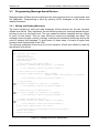
3.4
Optimising Programs using the ProDAQ 3020 Interface
To optimize you programs using the ProDAQ 3020 USB 2.0 VXIbus Slot-0 Interface,
please keep the following in mind:
Use the functions viMove, viMoveIn or viMoveOut instead of single read and write
commands for devices and register ranges, where this is possible.
Use the attributes VI_ATTR_SRC_PRIV and VI_ATTR_DEST_PRIV to specify
block transfer privileges for devices where this is possible.
Use 32-bit or 64-bit moves, whenever possible.
Align your buffers to 32-bit boundaries. Locking this buffer in memory and allocating
a contiguous buffer will help to optimize the performance.
Copyright, © 2003 Bustec Production Ltd.
Page 41 of 60
3020-XX-UM
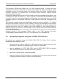
3.5
ProDAQ 3020 USB2.0 VXIbus Slot-0 Interface User Manual
Using VXIbus and Front Panel Trigger Lines
One feature, that differs the VXIbus from other busses, is its ability to use trigger signals to
communicate with instruments in real-time, to share clock signals, etc. The VISA library
implements functions to control those trigger lines from your application.
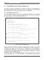
3.5.1 Using VXIbus Trigger Lines
The VISA standard implements the function viAssertTrigger together with the attribute
VI_ATTR_TRIG_ID to assert and de-assert trigger lines on the VXIbus or sending the
word serial trigger command to message-based devices.
#include <visa.h>
main (int argc, char **argv)
{
ViStatus status;
ViSession rm_session;
ViSession instr_session;
ViChar descr[256];
/* open a session to the resource manager */
if ((status = viOpenDefaultRM (&rm_session)) != VI_SUCCESS)
{
/* error handling as shown in the previous examples !*/
}
/* open a session to the instrument */
if ((status = viOpen (rm_session, “VXI0::2::INSTR”,
VI_NULL, VI_NULL, &instr_session)) != VI_SUCCESS)
{
/* error handling as shown in the previous examples !*/
}
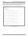
/* defining the trigger line to use */
if ((status = viSetAttribute (instr_session,
VI_ATTR_TRIG_ID, VI_TRIG_TTL0)) != VI_SUCCESS)
{
/* error handling as shown in the previous examples !*/
}
/* send a trigger pulse to the device */
if ((status = viAssertTrigger (instr_session, VI_TRIG_PROT_SYNC)) != VI_SUCCESS)
{
/* error handling as shown in the previous examples !*/
}
/* close the sessions to the instrument and the resource manager */
viClose (instr_session);
viClose (rm_session);
}
Figure 35 - Sending a Trigger Pulse
Figure 35 shows an example for sending a trigger pulse to a device. The function
viSetAttribute is used () to set the attribute VI_ATTR_TRIG_ID to select the trigger line.
In general the trigger ID can be set to VI_TRIG_TTL0 to VI_TRIG_TTL7,
VI_TRIG_ECL0/VI_TRIG_ECL1 or VI_TRIG_SW. For the setting VI_TRIG_SW, the device
is sent the word serial trigger command, the other settings correspond to the VXIbus
trigger lines TTL0-TTL7 and ECL0/ECL1.
To send the trigger, the function viAssertTrigger is used in the example () with the
“protocol” argument set to VI_PROT_DEFAULT. The interpretation of this argument
Page 42 of 60
Copyright, © 2003 Bustec Production Ltd.
ProDAQ 3020 USB 2.0 VXIbus Slot-0 Interface User Manual
3020-XX-UM
depends on the value, the attribute VI_ATTR_TRIG_ID is set to. For software triggers, the
only valid protocol is VI_PROT_DEFAULT. For hardware triggers, the protocols
VI_PROT_DEFAULT or VI_PROT_SYNC will generate a trigger pulse on the specified
line, while VI_PROT_ON and VI_PROT_OFF let you explicitly assert and de-assert the
trigger line.
3.5.2 Using Front-Panel Trigger Lines
The ProDAQ 3020 supports a front-panel trigger input and output, which can be mapped
to the VXIbus trigger lines. For this purpose, as for querying and manipulating other
VXIbus backplane specific lines, the VISA standard implements a special resource. It
encapsulates the VXI-defined operations and properties of the backplane in a VXIbus
system. It lets a controller query and manipulate specific lines on a specific mainframe in a
given VXI system. Services are provided to map, unmap, assert, and receive hardware
triggers, and also to assert various utility and interrupt signals.
The resource descriptor used for the backplane resource is again a combination of
interface type and number, logical address of the VXI device, and the device type
BACKPLANE:
VXI 0 :: 0 :: BACKPLANE
Interface Type
Interface Number
Device Type
Logical Address
As before, the interface type when using the ProDAQ 3020 Interface is always “VXI”. The
interface number depends on the assignment you made using the configuration utility (see
2.5 Configuring the ProDAQ 3020 for the VISA Library). The logical address will be zero
(0), as you will need to configure the ProDAQ 3020 for logical address zero to allow it to
function as a VXIbus slot-0 controller.
Though the ProDAQ 3020 does not support the mapping of one VXIbus trigger line to
another, the standard VISA functions viMapTrigger and viUnmapTrigger can be used to
map the front panel trigger input to one or many of the VXIbus trigger lines as well as to
map one or many VXIbus trigger lines to the front panel trigger output.
Figure 36 shows an example how to map the trigger lines to/from the front panel input and
output. First a session for the backplane resource is opened (). Then the function
viMapTrigger is used to map the front panel input to the VXIbus trigger line TTL1 (), and
also to the VXIbus trigger lines ECL0 (). This means that whenever an active trigger is
detected on the front panel input of the ProDAQ 3020, both lines will be asserted. In
general, when the viMapTrigger function is called multiple times with the same source
trigger line and different destination trigger lines, an assertion of the source line will cause
all of those destination lines to be asserted. To select how the ProDAQ 3020 will detect am
active trigger on the front panel input, see 2.6.3: Configuring the Front Panel I/O.
To map one or multiple of the VXIbus trigger lines to the front panel output, the value
VI_TRIG_PANEL_OUT must be used for the destination parameter (). As with the front
Copyright, © 2003 Bustec Production Ltd.
Page 43 of 60
3020-XX-UM
ProDAQ 3020 USB2.0 VXIbus Slot-0 Interface User Manual
panel input, multiple lines can be mapped to the front panel output. When calling
viMapTrigger multiple times with the same destination line and different source lines, the
destination line will be asserted when any of the source lines is asserted. To select the
active level of the front panel output, see 2.6.3: Configuring the Front Panel I/O.
#include <visa.h>
main (int argc, char **argv)
{
ViStatus status;
ViSession rm_session;
ViSession instr_session;
ViChar descr[256];
/* open a session to the resource manager */
if ((status = viOpenDefaultRM (&rm_session)) != VI_SUCCESS)
{
/* error handling as shown in the previous examples !*/
}
/* open a session to the instrument */
if ((status = viOpen (rm_session, “VXI0::0::BACKPLANE”,
VI_NULL, VI_NULL, &instr_session)) != VI_SUCCESS)
{
/* error handling as shown in the previous examples !*/
}
/* mapping the front panel input to trigger line TTL1 */
if ((status = viMapTrigger (instr_session,
VI_TRIG_PANEL_IN, VI_TRIG_TTL1, VI_NULL)) != VI_SUCCESS)
{
/* error handling as shown in the previous examples !*/
}
/* mapping the front panel input also to trigger line ECL0 */
if ((status = viMapTrigger (instr_session,
VI_TRIG_PANEL_IN, VI_TRIG_ECL0, VI_NULL)) != VI_SUCCESS)
{
/* error handling as shown in the previous examples !*/
}
/* mapping trigger line TTL6 to the front panel output */
if ((status = viMapTrigger (instr_session,
VI_TRIG_TTL6, VI_TRIG_PANEL_OUT, VI_NULL)) != VI_SUCCESS)
{
/* error handling as shown in the previous examples !*/
}
/* close the sessions to the instrument and the resource manager */
viClose (instr_session);
viClose (rm_session);
}
Figure 36 - Mapping Trigger Lines
Page 44 of 60
Copyright, © 2003 Bustec Production Ltd.
ProDAQ 3020 USB 2.0 VXIbus Slot-0 Interface User Manual
3020-XX-UM
4. Programming GPIB Devices using the ProDAQ 3020
Interface
The ProDAQ 3020 USB 2.0 VXIbus Slot-0 Interface features an optional GPIB port on the
front-panel (ProDAQ 3020-AB and ProDAQ 3020-BB only). This chapter shows how to use
the ProDAQ 3020 and the Bustec VISA library to program GPIB devices.
4.1
Connecting to a Device
The GPIB port on the ProDAQ 3020 can be used like any GPIB port installed via an
interface card in your computer. After using the configuration tool to assign an interface
number, devices connected to the GPIB port on the ProDAQ 3020 can be addressed by
using a standard VISA resource name. For GPIB devices, this resource name is a
combination of interface type, interface number, GPIB address and device type:
GPIB0 :: 2 :: INSTR
Interface Type
Device Type
Interface Number
GPIB Address
The interface type for the GPIB port on the ProDAQ 3020 USB2.0 VXIbus Interface is
always “GPIB”. The interface number is the number, which was assigned to the particular
3020 by using the VISA configuration utility (see 2.5Configuring the ProDAQ 3020 for the
VISA Library). The GPIB address is the address configured on the GPIB device.
For some GPIB devices, a secondary address is necessary to select for example a special
function on the device. In this case the resource name can be extended to contain also a
secondary GPIB address:
GPIB0 :: 2 :: 1 :: INSTR
Interface Type
Interface Number
Device Type
Primary Address
Secondary Address
The device type for GPIB instruments is always “INSTR”.
Copyright, © 2003 Bustec Production Ltd.
Page 45 of 60
3020-XX-UM
4.2
ProDAQ 3020 USB2.0 VXIbus Slot-0 Interface User Manual
Reading and Writing Messages to/from a GPIB Device
The following example shows how to connect to a GPIB device and how to write and read
messages to/from the device:
#include <visa.h>
main (int argc, char **argv)
{
ViStatus status;
ViSession rm_session;
ViSession instr_session;
ViChar descr[256];
/* open a session to the resource manager */
if ((status = viOpenDefaultRM (&rm_session)) != VI_SUCCESS)
{
/* error handling as shown in the previous examples !*/
}
/* open a session to the instrument */
if ((status = viOpen (rm_session, “VXI0::2::INSTR”,
VI_NULL, VI_NULL, &instr_session)) != VI_SUCCESS)
{
/* error handling as shown in the previous examples !*/
}
/* reset the device */
if ((status = viPrintf (vi, “*RST\n”)) != VI_SUCCESS)
{
/* error handling as shown in the previous examples !*/
}
/* ask the device for its identification */
if ((status = viPrintf (vi, “*IDN?\n”)) != VI_SUCCESS)
{
/* error handling as shown in the previous examples !*/
}
/* read the identification sent back */
if ((status = viScanf (vi, “%256t”, descr)) != VI_SUCCESS)
{
/* error handling as shown in the previous examples !*/
}
printf (“Device Identification: %s\n”, descr);
/* close the sessions to the instrument and the resource manager */
(instr_session);
viClose
viClose (rm_session);
}
Figure 37 – Reading and writing messages to/from a GPIB device
As explained in 3.1 - Connecting to a Device, the first step in a program using the VISA
library is always to open a session to the default resource manager (). It provides
connectivity to all VISA resources registered with it and gives applications control and
access to individual resources.
The next step is to open a session to the instrument () using a resource name as
explained above. Once the session is established, the standard functions viPrintf () and
viScanf () can be used to write messages to the device and read the response.
As a last step the sessions to the device and to the default resource manager need to be
closed ().
Page 46 of 60
Copyright, © 2003 Bustec Production Ltd.
ProDAQ 3020 USB 2.0 VXIbus Slot-0 Interface User Manual
3020-XX-UM
5. VXIbus Configuration Register Details
5.1
Address Map
All addresses are given in hexadecimal notation. Offset value is an offset in relation to the
base address in A16 address space as defined by the logical address.
Offset
0x00
0x02
0x04
0x06
0x08
0x0A
to
0x3F
5.2
Name
ID
LogAdr
DevType
Status
Control
Not Used
MODID
Access
RO
WO
RO
RO
WO
--RW
Not Used
---
Description
ID Register
Logical Address Register
Device Type Register
Status Register
Control Register
MODID Register
Register Description
5.2.1 ID Register
Bit
Operation
Initial
Contents
15
RO
14
RO
13
RO
12
RO
1
1
1
1
Device
Class
11
RO
1
10
RO
1
9
RO
1
8
RO
0
7
RO
0
Address
Space
Device Class
6
RO
1
5
RO
1
4
RO
1
3
RO
0
2
RO
0
1
RO
0
0
RO
0
ManufacturerID
This field indicates the module as a Register Based VXIbus
device.
This field determines the addressing mode of the device's
operational registers. This board is A16 only.
The manufacturer ID is 0xE70 (3696) and has been assigned by
the VXIbus Consortium. This number uniquely identifies the
manufacturer of the device as Bustec Production Ltd.
Address Space
Manufacturer ID
5.2.2 Logical Address Register
Bit
Operation
Initial
Contents
15
X
14
X
13
X
12
11
X
X
Not Used
10
X
9
X
8
X
7
WO
0
6
WO
0
5
WO
0
4
3
2
WO WO WO
0
0
0
LogAddr[7:0]
1
WO
0
0
WO
0
This register is used to assign a logical address to the module. If a static logical address is
assigned to the module (by using the VISA configuration utility), it is initialized to this static
Copyright, © 2003 Bustec Production Ltd.
Page 47 of 60
3020-XX-UM
ProDAQ 3020 USB2.0 VXIbus Slot-0 Interface User Manual
value at power-up. If a logical address of 255 (FFhex) is assigned to the module, it will take
part in the dynamic configuration protocol and the resource manager will use this register
to assign a logical address to the module.
5.2.3 Device Type
Bit
15
14
13
12
11
10
9
8
7
6
5
4
3
2
1
0
Operation
Initial
RO
RO
RO
RO
RO
RO
RO
RO
RO
RO
RO
RO
RO
RO
RO
RO
0x00CC if slot-0, 0x0BCC otherwise
Contents
ModelCode[15:0]
ModelCode[15:0]
This field contains a device dependent type identifier. As defined
by the VXIbus standard, the module uses two different identifier,
depending on whether the module is placed in the left most slot of
a VXI mainframe (slot “0”) and is used as VXI slot-0 controller or
not:
Identifier when used as slot-0 controller:
Identifier when not used as slot-0 controller:
0x00CC
0x0BCC
12
X
Contents
MODID*
Slot 0
N.U.
MODID*
Slot 0
Logical Address
Ready
Passed
Page 48 of 60
11
RO
H
10
RO
H
9
RO
H
8
RO
H
7
RO
H
6
RO
H
Logical Address
5
RO
H
4
RO
H
3
RO
H
2
RO
H
1
X
0
X
N.U.
13
RO
H
N.U.
14
RO
H
Passed
15
X
Ready
Bit
Operation
Initial
N.U.
5.2.4 Status Register
A one (1) indicates that the device is not selected via the P2
MODID line. A zero (0) indicates that the device is selected by a
high state on the MODID line.
A one (1) indicates that the module is in the leftmost slot of a
VXIbus system.
Contains the logical address the module is configured for.
A zero (0) means the device is executing its self-test.
After completing the self-test (signaled by a one (1) in the Ready
bit), the Passed bit indicates the state of the self-test. A one (1)
indicates that the self-test has successfully completed. A zero (0)
means that the device has failed its self-test.
Copyright, © 2003 Bustec Production Ltd.
ProDAQ 3020 USB 2.0 VXIbus Slot-0 Interface User Manual
3020-XX-UM
5.2.5 Control Register
14
13
12
11
10
9
8
7
6
5
4
3
2
X
X
X
X
X
X
X
X
X
X
X
X
X
X
1
Not Used
Contents
Sysfail Inhibit
0
WO WO
0
0
Reset
15
Sysfail
Inhibit
Bit
Operation
Initial
A one (1) written to this bit disables the device from driving the
SYSFAIL* line.
A one written to this field forces the device into a reset state.
Reset
5.2.6 MODID Register
Content
15
14
13
12
11
10
9
8
7
6
5
4
3
2
1
0
X
X
RW
0
RW
H
RW
H
RW
H
RW
H
RW
H
RW
H
RW
H
RW
H
RW
H
RW
H
RW
H
RW
H
RW
H
Not Used
Output Enable
MODID[12:0]
Output
Enable
Bit
Operation
Initial
MODID[12:0]
Writing a one to this bit enables the Slot 0 MODID driver. Writing a
zero disables the MODID driver. This bit is cleared (zero) by
device resets. When read, this bit indicates the state of the
MODID drivers. A one means the drivers are enabled, a zero
indicates that the drivers are disabled.
Writing a one to any of these bits drives the corresponding MODID
line high. Writing a zero drives the corresponding line low. Writing
to these bits has only effect, if the Output Enable bit is set. When
read, each of these bits indicates the actual level of the
corresponding MODID line.
Copyright, © 2003 Bustec Production Ltd.
Page 49 of 60
3020-XX-UM
Page 50 of 60
ProDAQ 3020 USB2.0 VXIbus Slot-0 Interface User Manual
Copyright, © 2003 Bustec Production Ltd.
ProDAQ 3020 USB 2.0 VXIbus Slot-0 Interface User Manual
3020-XX-UM
6. Front Panel Connectors and Switches
The ProDAQ 3020 USB2.0 VXIbus Slot-0 Interface features a USB connector, four clock
or trigger connectors, a reset switch and depending on the options a GPIB connector and
two trigger chaining connectors on its front panel.
6.1
ProDAQ 3020-AA Front Panel Connectors and Switches
6.1.1 USB Connector
bustec
ProDAQ 3020
The ProDAQ 3020 uses a standard USB “B” series receptacle suitable
for high-/full-speed devices. It mates with a standard “B” series plug
used on a host-to-peripheral A-to-B type USB cable (see Figure 4).
SYS VXI
FAIL Act.
USB
4
1
3
2
Pin
1
2
3
4
Shell
Signal
VBUS
DD+
GND
Shield
Description
Device Power
Differential Data
Differential Data
Ground
Shielding
Figure 38 - USB Connector Pin-out
6.1.2 Clk In/Out Connectors
The ProDAQ 3020 features a standard SMB connector for receiving (Clk
In) or distributing (Clk Out) the CLK10 signal from/to the VXIbus.
6.1.3 Trigger In/Out Connectors
Clk In
Clk Out
Trig In
Two SMB connectors allow to receive (Trig In) or to generate (Trig Out)
a TTL Trigger signal.
6.1.4 Reset Switch
Trig Out
A push-button reset switch can be used to reset the device.
RESET
Copyright, © 2003 Bustec Production Ltd.
Page 51 of 60
3020-XX-UM
6.2
ProDAQ 3020 USB2.0 VXIbus Slot-0 Interface User Manual
ProDAQ 3020-AB Front Panel Connectors and Switches
In addition to the connectors found on the ProDAQ 3020-AA, the ProDAQ 3020-AB
features an additional GPIB connector on its front-panel.
6.2.1 GPIB Port Connector
bustec
ProDAQ 3020
SYS VXI
FAIL Act.
USB
Clk In
Clk Out
Trig In
Trig Out
G
P
I
B
The ProDAQ 3020-AB features a standard 24-pin IEEE488 connector
for the GPIB port:
Pin
1
2
3
4
5
6
7
8
9
10
11
12
13
14
15
16
17
18
19
20
21
22
23
24
Signal
DIO1
DIO2
DIO3
DIO4
EOI
DAV
NRFD
NDAC
IFC
SRQ
ATN
SHIELD
DIO5
DIO6
DIO7
DIO8
REN
GND
GND
GND
GND
GND
GND
GND
Description
Data I/O 1
Data I/O 2
Data I/O 3
Data I/O 4
End of Information
Data Valid
Not Ready For Data
No Data Accepted
Interface Clear
Service Request
Attention
Shield
Data I/O 5
Data I/O 6
Data I/O 7
Data I/O 8
Remote Enable
Ground
Ground
Ground
Ground
Ground
Ground
Ground
12
11
10
9
8
7
6
5
4
3
2
1
24
23
22
21
20
19
18
17
16
15
14
13
RESET
Figure 39 - GPIB Port Connector Pin-out
Page 52 of 60
Copyright, © 2003 Bustec Production Ltd.
ProDAQ 3020 USB 2.0 VXIbus Slot-0 Interface User Manual
6.3
3020-XX-UM
ProDAQ 3020-BA Front Panel Connectors and Switches
In addition to the connectors available on the ProDAQ 3020-AA, the ProDAQ 3020-AB
features two additional micro-D style connectors for trigger daisy-chaining between
mainframes.
6.3.1 Trigger Chain In/Out Connectors
bustec
ProDAQ 3020
The trigger chain connectors on the front panel of the 3020-AB can be
used to connect the trigger lines of multiple VXIbus mainframes directly.
A standard 9-pin micro-D Connector is used with the following pin-out:
SYS VXI
FAIL Act.
USB
Clk In
Clk Out
Trig In
Pin
1
2
3
4
5
6
7
8
9
Shell
Signal
TTL0
TTL1
GND
TTL2
TTL3
TTL4
TTL5
TTL6
TTL7
GND
Description
VXIbus TTL Trigger Line 0
VXIbus TTL Trigger Line 1
Ground
VXIbus TTL Trigger Line 2
VXIbus TTL Trigger Line 3
VXIbus TTL Trigger Line 4
VXIbus TTL Trigger Line 5
VXIbus TTL Trigger Line 6
VXIbus TTL Trigger Line 7
Shield Ground
Trig Out
Trig. Chain.
In
9
8
7
6
Out
5
4
3
2
1
Trigger Chain In/Out
(Female)
Figure 40 - Trigger Chain Connectors Pin-out
RESET
Copyright, © 2003 Bustec Production Ltd.
Page 53 of 60
3020-XX-UM
6.4
ProDAQ 3020 USB2.0 VXIbus Slot-0 Interface User Manual
ProDAQ 3020-BB Front Panel Connectors and Switches
The ProDAQ 3020-BB features both the trigger chaining micro-D connectors and the GPIB
port connector in addition to the USB and trigger/clock connectors.
For all connector descriptions, see chapters 6.1, 6.2 and 6.3.
bustec
ProDAQ 3020
SYS VXI
FAIL Act.
USB
Clk In
Clk Out
Trig In
Trig Out
Trig. Chain.
In
Out
G
P
I
B
RESET
Page 54 of 60
Copyright, © 2003 Bustec Production Ltd.
ProDAQ 3020 USB 2.0 VXIbus Slot-0 Interface User Manual
3020-XX-UM
Specifications
6.5
6.6
Interface Characteristics
Interface Type
USB 1.1 and USB 2.0 Compliant
Operating Systems
Windows NT, Windows 2000, Windows XP
Languages
C/C++, Visual
HP/Agilent Vee
Controllers
PC compatible
Basic,
LabVIEW,
LabWindows/CVI,
VXIbus Characteristics
General
Device Type
Register-Based
Size
C
Slots
1
Connectors
P1/P2
Slot-0 Functionality
Yes, auto-detected
Resource Manager Functionality
Yes
VXIbus Master
Address Space
A16, A24 and A32
Data Transfer Capabilities
D08, D16, D32, D16BLT, D32BLT, D64MBLT
BLT/MBLT Address Increment
Software Selectable
Bus Timer
16, 32, 64, 128, 256, 512 and 1024 µs
VXIbus Slave
Address Space
A16
Size
64 Bytes
Base Address
0xC000 + Logical Address * 0x40
Data Transfer Capabilities
D08, D16 and D32
Copyright, © 2003 Bustec Production Ltd.
Page 55 of 60
3020-XX-UM
ProDAQ 3020 USB2.0 VXIbus Slot-0 Interface User Manual
VXIbus Requester
Request Level
BR0 to BR3
Request Mode
“Fair” or “On Demand”
Release Mode
ROR, RWD
VXIbus Arbiter
Arbitration Mode
SGL, PRI, RRS
Arbitration Time-out
10 µs
VXIbus Interrupts
6.7
Interrupt Handler
IRQ1 to IRQ7
Interrupter
IRQ1 to IRQ7
Interrupter Release Mode
ROAK
Front Panel I/O
CLK10 In
Input Level
TTL
Input Protection
-5V to +10V
Connector Type
SMB
Note
When using an external clock to supply the CLK10 signal, you must use a VXIbus
standard compliant clock signal (10 MHz, equal or better than ±100 ppm, 50%±5%
duty cycle).
CLK10 Out
Output Level
TTL
Output Frequency*
10 MHz
Frequency Stability*
±100 ppm
Duty Cycle*
50%±5%
Connector Type
SMB
(* Specification valid for internal clock generator only)
Page 56 of 60
Copyright, © 2003 Bustec Production Ltd.
ProDAQ 3020 USB 2.0 VXIbus Slot-0 Interface User Manual
3020-XX-UM
Trigger In
Input Level
TTL
Active Edge
Software selectable
Trigger Detection
- Routable to VXIbus trigger lines TTL0 to TTL7, ECL0/1
- Interrupt on trigger detection
Input Protection
-5V to +10V
Connector Type
SMB
Trigger Out
Output Level
TTL
Active Level
Software selectable
Trigger Generation
- From VXIbus trigger lines TTL0 to TTL7, ECL0/1
- By software command
Maximum Current
-32 mA (IOH) / 64 mA (IOL)
Connector Type
SMB
Trigger Daisy-chain In
Input Level
TTL, active low
Input Protection
0V to +5V
Connector Type
9-pin micro-D (female)
Trigger Daisy-chain Out
Input Level
TTL, active low
Maximum Current
-32 mA (IOH) / 64 mA (IOL)
Connector Type
9-pin micro-D (female)
GPIB Port
6.8
Interface Level
IEEE488.2
Connector Type
24-pin standard IEEE488
Power Supply Loading
Current Consumption
+5 V:
-5.2 V:
-2 V:
Total Power Consumption
< 9.2 W
Copyright, © 2003 Bustec Production Ltd.
0.9 A typ., 1.4 A max.
0.3 A max.
0.3 A max.
Page 57 of 60
3020-XX-UM
6.9
ProDAQ 3020 USB2.0 VXIbus Slot-0 Interface User Manual
Miscellaneous
Operating Temperature
0º to 50º C
Storage Temperature
-40º to +70º C
Humidity
0-90%, non-condensing
Cooling
1 l/s @ 0.25mm H2O
Weight
950 g
Page 58 of 60
Copyright, © 2003 Bustec Production Ltd.
Bustec Production, Ltd.
World Aviation Park, Shannon, Co. Clare, Ireland
Tel: +353 (0) 61 707100, FAX: +353 (0) 61 707106
Bustec, Inc.
17820 Englewood Dr #14, Middleburg Hts, OH 44130, U.S.A
Tel. +1 440 826 4156, Fax: +1 440 826 4184