1
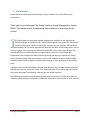
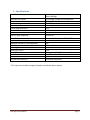
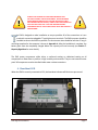
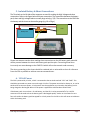
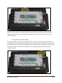
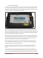
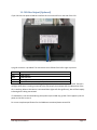
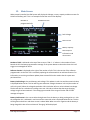
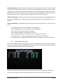
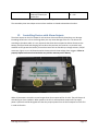
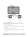
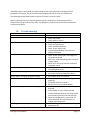
Elite Power Solutions Energy Management System Operation Manual Elite Power Solutions 1622 W 12th Place Tempe, AZ 85281 www.elitepowersolutions.com EMS Operation Manual Page 1 Table of Contents 1. Introduction 2. Specifications 3. Typical Schematic 4. Heartbeat LED 5. Isolated Shunt and Battery Wiring 6. 12V Power 7. Page Select Input 8. Sense Board Wiring 9. Battery Balancing 10. Video Output 11. CAN Bus Option 12. Main Screen 13. Individual Cell Screen 14. Alarms 15. Controlling Devices with Alarm Outputs 16. Capacity Algorithm 17. Ground Fault Detection 18. Troubleshooting Appendix A: Enclosure Mounting EMS Operation Manual Page 2 1. Introduction Please read this manual before attempting to install or operate any of the EMS system components. Thank you for purchasing an Elite Power Solutions Energy Management System (EMS). This manual covers the operating and installation information for this system. he EMS system has everything needed to display the condition of and maintain the health of lithium ion batteries and is specifically designed to work with GBS Lithium Ion batteries. The system consists of two major components, the computer (CPU) and the cell sense boards. The CPU shows many details about the condition of the battery pack, such as current, voltage, state of charge and individual cell details, via its video output display. The sense boards form a simple daisy chain by mounting on each cell to read voltage and temperature; they also perform battery balancing during recharging to equalize the charge within the battery pack. Two alarm outputs, one for over voltage and one for under voltage, provide automatic shut off signals to prevent overcharging or over discharging of the battery pack. A unique feature of the EMS system is ground fault detection. High voltage systems should be floating relative to the chassis for safety. If an inadvertent path to the chassis ground is made the system will detect it and display a warning for this unsafe condition. The EMS outputs composite video to display battery pack information. A CAN (controller area network) interface option is available to output the information from the EMS to other systems. EMS Operation Manual Page 3 2. Specifications Main Screen Display Individual Cell Screen Computer Input Power Battery Voltage Shunt Input Pack Voltage Resolution Current Resolution Temperature Measurement Range Battery Types Supported Pack Voltage, Pack Current, Battery Capacity, Alarm Message Cell number, voltage and temperature 9-20V, 120mA 12-500V 500A = 50mV 0.2V 0.1A -99F to +199F or -146 to +92C Lithium Ion Video Output Measurement accuracy Maximum number of cells supported Cell Voltage Balancing Threshold Balancing Current Alarm Output Current Alarm Output Delay Optional Data Interface Ground Fault Detection Composite Video, Color, NTSC, RS-170 Better than 1% of Full Scale 140 2.2V to 4.5V 3.55V 0.5A 4A surge for 100mS, 2A continuous* See Default Alarm Table in section 14 CAN 2mA (5000 Ohm/Volt) *12V input must be able to supply the power used by the alarm outputs EMS Operation Manual Page 4 3. Typical Schematic EMS Operation Manual Page 5 ALWAYS USE EXTREME CAUTION WHEN WORKING HIGH VOLTAGE SYSTEMS. ALWAYS DIDCONNECT THE MAIN POWER WHEN WORKING ON ANY HIGH VOLTAGE SYSTEM (THIS WILL HELP MINIMIZE RISK OF SHOCK). ALWAYS TAKE NOTE WHERE THE HIGH VOLTAGE LINES ARE. IF YOU ARE UNCOMFORTABLE PERFORMING ANY OF THESE TASKS PLEASE STOP AND CONSULT A PROFESSIONAL. he EMS is designed to make installation as easy as possible. All of the connections to it are made with convenient pluggable ¼” quick disconnect terminals. The EMS computer should be installed as close to the shunt as possible. The shunt sense wires should be less than 1’ long. A mounting template for the computer is shown in Appendix A. After the installation is complete, the battery pack must be completely charged before the capacity will read correctly (see Section 7. Capacity Algorithm for more details). The EMS system components utilize either a conformal coating or rubberized coating on all components to allow them to perform in high humidity environments. They are not however water proof. All components must be installed inside water resistant containers. 4. Heartbeat LED When the EMS is correctly connected to 12V, the heartbeat indicator will blink once per second. EMS Operation Manual Page 6 5. Isolated Battery & Shunt Connections The Terminals on the left side of the computer are used for making the High-Voltage and shunt connections. Refer to the figure below for these connections. The connections between the battery pack, shunt and high voltage loads are usually large wire (e.g. 2/0). The connections to the EMS from the battery and the shunt can be smaller gauge (e.g. 18 or 20 ga). + - + Battery Pack - Load Please use extreme caution when making these connections as the full battery pack potential will be present between the shunt and battery pack positive pins. Connecting these wires incorrectly can cause damage to the EMS CPU which will not be covered under warranty. The wires connecting to the shunt should be a twisted pair or wires with as short of a distance from the CPU as possible to achieve accurate measurements. 6. 12 Volt Power The CPU is powered by 12 volts, which is connected to the terminals marked “12V” and “GND”. This should be connected to a power source through a 5A fuse. The power can either be always on, or can be switched off to conserve power. 12 volt power must be supplied at any time when the battery pack is being charged or discharged. When 12 volt power is applied the red heartbeat LED will blink. If the battery pack is more than a 12 volt battery, and the CPU is to be powered off of it, a DC/DC converter must be used so that the battery pack is discharged equally. Under no circumstances can a four cells within the battery pack be tapped for 12 volt power for the CPU as this will cause an imbalance within the battery pack. EMS Operation Manual Page 7 Note that there are three pins marked “GND” for ground on the CPU. These three pins are common together. Only one of these pins needs to be connected, the other two are located for convenient connection options. 7. Page Select Switch Input To change the display on the CPU to the individual cell screen(s) a normally open momentary switch is used to short the pins marked (MDE) to (GND). There is no polarity to the switch and the connection can be small gauge wire (e.g. 18 ga). In applications where the 12 volt power is grounded to a vehicle chassis only one wire needs to be ran from the MDE pin and can be grounded to the chassis through the momentary switch. EMS Operation Manual Page 8 8. Sense Board Wiring The sense boards are connected to the CPU via a cable with five pins. Depending on which sense board version the system was supplied with this cable will have either four or five wires connected to it. This connector has a retention mechanism. If removal of this cable is needed never pull in the wires, always pull up on the connector, to avoid damage to the wire harness. The CPU will automatically index the sense boards based on their position in the daisy chain of sense boards. The first sense board connected to the CPU will be cell number one and will count up from there. It is recommended that the negative most cell in the pack be made cell number one and have the daisy chain move toward the most positive cell in the pack. This will aide in troubleshooting if needed; however, the sense boards can be connected in any order. Before installing sense boards, install all cell jumpers first with the outer two screws tightened. Never install sense boards underneath jumpers as this will cause current to flow through the screws, which is a poor connection. Never slide a jumper underneath a sense board while installing as this may cause a short with components which are located on the back of the sense board. When installing sense boards, keep cell covers installed on all cells except the cell where the sense board is being installed. Do not allow sense boards to lie on battery terminals. This will help prevent accidental damage to sense boards during installation. The sense boards have an input and an output connector. Before installing, ensure that they are oriented in the appropriate direction. The male connector is the input; the female connector is the output. The sense boards have battery positive and negative indicated on them. Ensure that the polarity is correct before installing. The boards will not be damaged by a reverse polarity; however, they will not function. When a sense board is installed correctly the green led will light up. There is also a red LED on EMS Operation Manual Page 9 the sense board, which indicates cell balancing is occurring. This led will light up any time the cell voltage is 3.55V or higher. An example of Sense boards installed correctly. The daisy chain connection at the top connects the two sense board strings together. The sense boards, like the cells they attach to, alternate + and – for the series connection. The last string in the daisy chain is not terminated and will have its output connector not connected to anything. Should the installation have less than an even multiple of 4 cells, the cable may be cut close to the last sense board used. Be sure to cut the cable cleanly with no wires left exposed. Do not cut the cable with 12V power applied to the CPU! The resulting short circuit may damage the EMS computer. EMS Operation Manual Page 10 9. Battery Balancing When the battery voltage rises during charging to 3.55V or above the red balancing LED will light on the sense board to indicate the cell is balancing. The sense boards will draw 0.5A until the voltage has dropped below 3.55V. It is normal for some cells to balance more than others and some cells to rarely balance. 10. Video Output The EMS CPU outputs composite video output through a common RCA type jack. This can be connected to the optional LCD screen EPS provides or any other display which will accept this type of input (e.g. in dash DVD). The video cable is not provided as length requirements vary. A shielded cable is recommended if there is snow or static in the video signal. EMS Operation Manual Page 11 11. CAN Bus Output (Optional) If your CPU has the optional CAN bus interface this connector will be on the side of the CPU. A pig tail connector is provided. The connections are as follows from left to right as pictures: NC No Connection GND CAN Ground CANL CAN Low Data CANH CAN High Data 12V Optional 12V input, not typically used When making a connection to an EPS charger only the GND, CANL and CANH pins are used. Two LED’s will light when there is nothing connected to the CAN output, but indicate that the CAN portion of the CPU is working. When a CAN device is connected these lights will dim significantly, but will flash rapidly indicating data is being transmitted. If a CAN device is not connected during initial power up the COM may go idle. If this happens cycle the power to the CPU to reset it. For a more complete specification for the CAN data transmitted please contact EPS. EMS Operation Manual Page 12 12. Main Screen When properly installed, the EMS system will display the Voltage, current, capacity and alarm status of a Lithium Ion battery pack. This is an example of what the main screen displays: Number of programmed cells Software Version Pack Voltage Pack Current Battery Capacity Pack max/min information and alarm status Number of Cells is indicated at the top of the screen as “E.M.S – x” where x is the number of sense boards the CPU has been programmed to manage. If the system detects a value other than this it will trigger an unmanaged cell alarm. Software Version is displayed to the right of the number of cells. This is the version of the software programmed in to the CPU. EPS is constantly updating the software which can add new features. For information on receiving a software update please contact EPS or the vendor that the system was purchased from. Battery Pack Voltage is the total battery pack voltage. This updates in real time and the numerical value is displayed below the bar. This bar will be green whenever voltage is between 3.0V x N (the number of cells in the pack). When the voltage drops below 3.0V x N the bar will turn red to indicate low voltage. The bar will also turn red when the voltage rises over 3.4V x N to indicate that the target charging voltage range has been attained. If the voltage goes outside of the range of the bar and off scale message will appear. Battery Pack Current is the current either being drawn from the battery or being recharged in to it. Like the voltage bar this is indicated in real time and the numerical value is displayed below the bar. This bar will be green and will turn red when current is above 200A. When current is negative and the battery is being charged this bar will turn white and “Charging” will be displayed. EMS Operation Manual Page 13 Battery Pack Capacity is the battery state of charge. It works by tracking the amount of charge that goes in and out of the battery pack. It will reset to 100% during charging when the current is within a normal charging range for a battery charger and the total battery pack voltage reaches 3.52 x N (the number of cells). When the system is powered up for the first time this value will read 50%. The battery will have to be charged to full in order to reset the capacity reading correctly to 100% the first time. Min/Max Cell Voltage provides a quick overview of the maximum and minimum cell voltages within the battery pack. Depending on the number of cells within the battery pack, these values update every 1 -2 seconds. Alarms and Warnings are displayed at the bottom of the screen after the word “Pack:”. There are seven alarms: - Over voltage (highest cell is over 3.8V after a 3 second delay) Under voltage (lowest cell is below 2.8V after a 30 second delay) Over current (current exceeds 10C for 10 seconds) Over temperature (highest cell exceeds 150°F or 65°C) Under temperature (lowest cell is below 32°F or 0°C, charging is not allowed) Ground fault (There is a high voltage leakage greater than 2mA to the chassis pin) Unmanaged cells (The programmed number of cells does not equal the number of cells read) 13. Individual Cell Page To access the individual cell detail page(s) refer to section 7, Page Select Switch Input. When momentary switch is pressed and released it will change the display to show the first 20 cells in the pack with details of voltage and temperature of each cell as shown below: If there are more than 20 cells in the pack pressing the button again will advance to the next 20 cells until the last cell page is reached, then pressing the button again will return to the main screen. EMS Operation Manual Page 14 Cell (number) is the location of the sense board relative to the daisy chain of sense boards. The cell connected to the CPU first is number one. Volts is the actual cell voltage. This updates every 1-2 seconds, depending on the number of cells in the pack. Temp is the temperature reading. This updates every 1-2 seconds, depending on the number of cells in the pack. The number will turn red if the cell exceeds the upper temperature limit. Readings are in °F by default; however, upon request, this can be set to read in °C. The cell temperature is measured at the positive terminal of each sense board. If a single cell has noticeably higher temperature during use than other cells, but the temperature goes back down quickly this may be an indication of a poor connection where there is high contact impedance. Also, during balancing the temperature will temporarily rise due to the energy being converted to heat. Note that this screen will not automatically update if more or less cells are connected during installation. To update the screen the Page Select button must be pressed until it has cycled back through the main screen, then back to the individual cell detail screens in order to update the view. Cell voltage and temperatures are updated in real time on these screens. 14. Alarms In order to protect the battery pack there are a number of alarms, which are based on cell voltage, temperature and pack current and fault conditions. The CPU contains two alarm output pins, UV for under voltage and OV for over voltage. When any of the alarm conditions are met for a specified duration of time they will activate their respective action listed in the table below: Default Alarm Table Alarm Under Voltage Over Voltage Over Current Under Temperature Over Temperature Unmanaged Cells EMS Operation Manual Condition(s) Minimum cell voltage is below 2.8V Maximum cell voltage is above 3.8V Pack current exceeds 10C Minimum cell temperature is less than 32°F (0°C) Maximum cell temperature is greater than 150°F (65°C) The number of sense boards detected does not equal the programmed value Delay Time 30 seconds 3 seconds 10 seconds 30 seconds Actions UV = 0V OV = 12V UV= 12V OV = 0V UV = 0V OV = 0V UV = 12V OV = 0V 30 seconds UV = 0V OV = 0V 30 seconds UV = 0V OV = 0V Page 15 Pack to chassis fault Pack voltage exceeds 30 seconds 2mA to the chassis pin on the CPU The alarm limit values may vary with special request configurations. UV = 12V OV = 12V The same delay time must elapse once an alarm condition is cleared to deactivate the alarm. 15. Controlling Devices with Alarm Outputs The alarm outputs on the CPU output 12 volts and can drive continuously 2A with up to a 4A surge. Exceeding these limits or short circuiting these pins may cause damage to the CPU. The alarms act according to the above table. It is very important that these alarm outputs be able to disconnect the battery pack from loads and charging sources when they activate; this must be a no parasitic load condition to fully protect the battery. Ensure that items such as controller pre-charge resistors, DC/DC converters, lights, etc. are all disconnected in the event that the low voltage alarm triggers. Failure to properly implement these alarm interlocks may void the warranty on the battery. When all parameters are within normal ranges these alarm outputs will be 12 volts. They will drop to 0 volts during an alarm condition. When power to the CPU is removed these outputs will not supply power. Systems should be designed such that they require power from the alarm outputs from the CPU in order to function. EMS Operation Manual Page 16 GND 12 V UV OV GND 12V Supply Load Enable/Disable 16. Charger Logic Enable/Disable Capacity Algorithm The EMS CPU keeps track of the capacity of the battery pack by tracking current in and out of the battery (coulomb counting). There are however several corrections built in to the software to ensure that the capacity stays accurate over time. The capacity will reset to 100% if the following conditions are met: - Total pack voltage measures 3.52V x N (N being the number of cells) when being charged by a battery charger. The capacity will reset to 100% if the following conditions are met: - The over voltage alarm is triggered when being charged by a battery charger, see default alarm table for set points. EMS Operation Manual Page 17 The capacity will reset to 0% if the following conditions are met: - The under voltage alarm is triggered and discharging current is not excessive, see default alarm table for set points. When the EMS is powered up the first time the capacity will read 50%, which is approximately the state of charge that the batteries ship at when new. To sync the capacity the first time the battery pack must be charged full, which will trigger a reset to 100%. The capacity measurement is done based on the programming in the CPU. CPU’s cannot be interchanged with one which has been programmed for a different battery pack configuration. Upon special request the CPU can be programmed to extend battery life by limiting the depth of discharge to 80%. This will scale the capacity bar such that 100% of the scale is 80% of the battery capacity. Once the capacity reaches 0%, which is 20% of the actual capacity remaining, the under voltage (UV) output will automatically shut off. 17. Ground Fault Detection The pin marked “Chassis” is used for the ground fault detection circuitry integrated in to the EMS CPU. This should be connected to its own dedicated chassis ground point. When this is done and the shunt and battery positive wires are connected properly the system will be able to detect a ground fault anywhere within the battery pack. This feature will display an alarm message on the screen if there is a fault condition, but will not cause any alarm actions to be taken. If this message appears there is a potentially dangerous ground fault condition which should be corrected. The alarm will be triggered any time a current of 2mA or greater is detected from the battery pack to the chassis pin. EMS Operation Manual Page 18 If the EMS system is being used on a lower voltage system (<50 volts) where the battery pack is grounded to the chassis, this wire should not be installed to disable this feature. EPS does not recommend grounding battery packs in excess of 12 cells in series for safety. When performing work on a high voltage battery pack, the Chassis pin should temporarily be disconnected as it will induce a very small, non-dangerous, current to the chassis which could cause small electrical shocks. 18. Troubleshooting Symptom No heartbeat led on CPU No Video Sense Boards not detected Data jumps around rapidly No pack voltage reading No pack current reading Current shows “charging” during discharging No CAN data Pack has unmanaged cells alarm message appears Cell voltage too low alarm appears EMS Operation Manual Possible Causes Check 12 volt input power Check video cable Check power to screen Check for green LED on sense boards Check wiring for breaks Check Sense Board polarity Check 12 volt input to CPU Cycle through individual cell screen(s) to update information Check 12 volt input to CPU, low voltage will cause data to be bad EMI noise, route data cabling away from high voltage cabling Noise on 12 volt input, test with isolated 12 volt power source Check wiring at BT+ and SH-, pack voltage should be present here Check SH+ and SH- connections to the shunt All current must pass through the shunt SH+ and SH- wires are reversed CAN device must be connected during initial power up. CANH and CANL are reversed BAUD rate not correct (500K default) Check individual cell screen for number of cells detected. If the number of cells is deficient to the number expected check the last sense board which shows up and the first that does not. Check cell voltages with a multi meter. V2 sense boards will lose communication if voltage drops below 2.2V Pack is discharged and needs to be recharged Bad battery cell Page 19 Cell voltage is too high alarm appears Cell temperature is too high Cell temperature is too low Pack to chassis fault alarm appears Pack is charged and has shut off the charging source to protect itself Bad battery cell A sense board is reporting a temperature above the spec limit and is shutting down the system to protect the battery Check for loose connections A sense board is reporting a temperature below the spec limit for charging and has shut off charging equipment to protect the battery pack A potentially dangerous leakage current to the chassis has occurred. Find the source of this leakage and remove it. For low voltage systems where the battery pack is grounded to the chassis disconnect this pin to eliminate this feature. Appendix A: Enclosure Mounting EMS Operation Manual Page 20