1
Low Power and Embedded
Systems - Workbook 2
Introduction
In this workbook we will cover Serial communications and the use of the Analogue to Digital Converter.
Supporting material
atmega168P.pdf
http://www.cl.cam.ac.uk/teaching/0910/P31/docs/atmega168P.pdf
Data sheet for the Atmel ATMEGA168P used in these exercises. You
will need to refer to this frequently. Within these workbooks this will be
referred to as 'the datasheet' The section numbers referred to in these
workbooks refer to revision 8161C of the datasheet dated 05/09.
Serial Lead
http://www.cl.cam.ac.uk/teaching/0910/P31/docs/usbseriallead.pdf
Specification for the Serial/USB lead used in Exercise 1.
USART_functions.c
http://www.cl.cam.ac.uk/teaching/0910/P31/code/USART_functions.c
Library USART functions for exercise 3.
connect_pot.pdf
http://www.cl.cam.ac.uk/teaching/0910/P31/docs/connect_pot.pdf
Circuit diagram for connecting a potentiometer.
Interrupt Vector Table
http://www.nongnu.org/avr-libc/user-manual/
group__avr__interrupts.html
Table of interrupt
microcontrollers.
vector
names
for
ATMEL
AVR
series
An on-line version of this guide is available at:
workbook2.html [http://www.cl.cam.ac.uk/teaching/0910/P31/workbook2.html]
You should check this page regularly for announcements and errata. You might find it useful to refer to
the on-line version of this guide in order to follow any provided web links or to cut and paste example
code.
A note on Register and other names
In the examples which follow, you will see references to register names such as UCSR0A and bit-position
names such as RXCIE0.
These names, and more importantly which ones are relevant depend upon the particular Atmel device
being used.
They are defined in the library headers included at the top of the program, for example #include <avr/
io.h>
The angle brackets <avr/io.h> instruct the compiler to search for the header files in the standard
library header location, /usr/lib/avr/include, which means the file io.h will be found at /usr/lib/avr/include/
avr/io.h
An instruction such as #include "config.h" (note quotes instead of angle brackets) instructs the
compiler to search for the file config.h in the current directory and its sub-directories first, then in the
1
Low Power and Embedded
Systems - Workbook 2
standard library header location. A later workbook will explain the use of a configuration file such as
config.h in more detail.
Variable definitions
The ATMEGA168 microcontroller is an 8 bit device. Unless you specifically need a 16 bit (or wider)
variable, you should define variables as 8 bits wide to save space.
The compiler accepts the following definitions, and the workbook examples will usually use the form
which specifies the width, eg uint8_t.
• uint8_t is used to define an unsigned 8 bit variable, identical to char
• int8_t is used for a signed 8 bit variable, identical to signed char
• uint16_t is used to define an unsigned 16 bit variable, identical to unsigned int
• int16_t is used for a signed 16 bit variable, identical to int
• uint32_t is used to define an unsigned 32 bit variable, identical to unsigned long. Avoid using
32 bit values unless there really is no alternative.
• int32_t is used for a signed 32 bit variable, identical to long.
• uint64_t is used to define an unsigned 64 bit variable, identical to unsigned long long. You
won't need to use it. The compiler makes a reasonable job of 16 bit values, but 32 bit will cause slow,
bloated code. 64 bit is far worse than that.
• int64_t is used for a signed 64 bit variable, identical to long long.
Exercises
Preparation
The exercises this week follow on directly from Exercise 2 of Workbook1.
Select embedded_systems/workbook2/exercise1 as your working directory. Take a copy of the C
program for Exercise2 from Workbook1, which you can use as a starting point for this exercise.
Also copy the Makefile as follows:
cd
cd
cp
cp
mv
~/embedded_systems
workbook2/exercise1
../../workbook1/exercise2/exercise2.c .
../../workbook1/exercise1/Makefile .
exercise2.c exercise1.c
We will reuse the LED flashing part from the previous exercise during testing.
As a first test, make sure that at switch-on the hardware still runs Exercise 2 of Workbook1. It
should run just as soon as power is applied.
To test the software, compile the code for ~/workbook2/exercise2.c and reprogram the device, to
verify that the toolchain is in place and that the C code is in a working state.
If make responds "make: Nothing to be done for `all'." then all output files (*.hex,*.elf,*.o) are up to
date. make will do nothing until a source file (*.c) changes, or until you type make clean which
removes the existing output files. A subsequent make will recreate everything from scratch.
2
Low Power and Embedded
Systems - Workbook 2
Exercise 1 - Hello World via a serial data link
Notation
The ATMEGA168 microcontroller has a single USART (Universal Synchronous and Asynchronous
Receiver and Transmitter). For a full description of USART operation see section 17 of the datasheet.
Older ATMEL devices only ever had 1 USART, and the data sheets and example code referred to 'The
USART' and its registers for example UCSRA.
Newer devices in the family may have more than one USART, so for reasons of compatibility these
devices, which include the ATMEGA168 refer to the USART by number even if there is only one, so the
USART would be referred to as USART0, and the register names also include the number for example
UCSR0A.
The Exercise
Transmitting data via a serial data link, either using the RS232 standard or by USB is a common
requirement. There are two complicating factors that we will need to consider in this part of the exercise:
1. Serial communication relies on a reasonably accurate clock for the Baud rate. The internal oscillator
would be accurate enough, but we will switch to using an external 14.746MHz crystal as the clock
source, which entails using the Full Swing Crystal Oscillator option for our microcontroller. We derive
the Baud rate clock for serial communication from this clock source.
2. RS232 uses positive and negative voltage levels, typically +9V -9 V which will require the use of a
voltage level converter. When viewing RS232 traffic with an oscilloscope, note that a 1 is represented
by a negative voltage, a 0 by a positive one. Not all PCs have serial ports, and so an alternative is to
use the USB interface on the PC, although this requires some additional hardware. In this exercise
we will use a converter lead which takes care of the voltage level conversion, and additionally carries
out the USB negotiation when the lead is first connected to the host PC.
Microcontroller Clock
Change the wiring on the prototype board to match that shown on page 31 of the
datasheet, using a 14.746MHz crystal and 33pF capacitors for C1 and C2. Note the
capacitors and crystal aren't polarised so you can fit them either way round. An example
photograph is available at crystal_connections.jpg [http://www.cl.cam.ac.uk/teaching/0910/P31/
docs/crystal_connections.jpg]
Refer to section 8.2 of the datasheet for Clock sources, and tables 8.5 and 8.6 for suitable SUT 1..0
and CLKSEL 3..0 settings for a Full Swing Crystal Oscillator with fast rising power. We don't want
the divide-by-8, so bit 7 of lfuse is 1 (=inactive); We still want CLKOUT active, so bit 6 of lfuse is 0.
Work out new values for the lfuse, check them with the demonstrator, then program the device
fuses in the same way as you did for exercise 1, i.e., just using the make fuses command.
Programming the fuses needs to be followed by a make program, a power cycle is not sufficient. You
previously copied workbook1/exercise2/exercise2.c to workbook2/exercise1. If no change has been
made to the program, then make program should cause the LED to flash at 14.746 Hz
Change the F_CPU setting defined in your program you have copied from workbook1 exercise
2, recompile, re-program and verify that you have a 1Hz LED flash. Remember from workbook
1 that the F_CPU setting must be correct for the _delay_ms() and _delay_us() functions
to give the correct delays. Update the comments in the file exercise1.c to reflect the new clock
arrangements and how the fuse bits are now set.
3
Low Power and Embedded
Systems - Workbook 2
Once this has been achieved, the first of the two problems has been solved - the device is running from
an accurate clock source.
USB connection
As part of the equipment available to you, there is an RS232 to USB converter lead. This takes the form
of a cable with USB type A plug on one end and a 6 way socket on the other. It contains a voltage level
converter and carries out the USB negotiation with the host.
A datasheet for this device is available from http://www.cl.cam.ac.uk/teaching/0910/P31/docs/
usbseriallead.pdf.
Also available is a home made, right angled 6 way adaptor. On this adaptor the thin pins fit into the
prototyping board, and the thicker, square pins connect to the USB lead.
Important Make sure you only fit the small pins in the prototyping board - the thick pins will damage
the board.
Refer to the datasheets for the USB lead and the ATMEGA168, and connect the USB serial lead
to the microcontroller as described below.
With all RS232 communications, there is the potential for confusion over Transmit vs Receive.
The microcontroller uses TxD to refer to the pin from which it will transmit. The USB lead uses the
term TXD to refer to data transmitted by the PC towards the microcontroller. Hence you need to
connect TxD (pin 3) on the microcontroller to Receive on the USB lead (the yellow wire).
A schematic is shown here: http://www.cl.cam.ac.uk/teaching/0910/P31/docs/connect_serial.pdf.
An example is shown here: http://www.cl.cam.ac.uk/teaching/0910/P31/docs/connect_serial.jpg.
PC serial software
Plug the USB serial lead into the PC.
Type dmesg at the terminal.
You should see something like:
usb 2-1:
ftdi_sio
usb 2-1:
usb 2-1:
configuration #1 chosen from 1 choice
2-1:1.0: FTDI USB Serial Device converter detected
Detected FT232RL
FTDI USB Serial Device converter now attached to ttyUSB1
The important part to note here is the ttyUSB1. The serial device has been recognised and can now
be referred to as /dev/ttyUSB1
4
Low Power and Embedded
Systems - Workbook 2
Start the minicom program in settings mode by typing minicom -s
Select serial port setup , Select A and select the serial device as ttyUSB1 (or whatever
name you got from the dmesg command)
Type E and select a baud rate of 19200, and a framing format with no parity, 8 data bits and 1 stop
bit, which will be shown at the top of the Comm parameters window as current: 19200 8N1
Make sure that both Hardware Flow control and Software Flow control are set to No. With flow
control enabled, the system will freeze waiting for a condition which will never occur.
Type Save setup as dfl
Select Exit to finish the configuration.
For a list of minicom commands type <ctrl>A Z
Note: to exit minicom, type <ctrl>A Q
Microcontroller software
Refer to section 19, and write a function to initialise the USART. You will need to refer to section 19.11
to set the correct values for baud rate and framing format, i.e. 19200 Baud, with 8 data bits, no parity
and 1 stop bit. This format is written in the style 19200,N,8,1 When calculating the throughput, note that
by default there is also 1 start bit, so transmitting a byte takes 10 bit times.
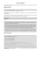
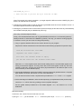
Here is a partial template
void USART0_Init(void) {
// add a value to Set baud rate to 19200, based
//
on 14.746MHz clock and single speed (U2X0 = 0)
//
See section 19.11 in the datasheet
UBRR0H = somevalue;
UBRR0L = somevalue;
UCSR0A = 0;
// Turn off double speed
// add a value to: Enable receiver and transmitter,
//
all other bits can be left=0
// See section 19.10 of the datasheet
UCSR0B = somevalue;
// add a value to Set: Asynchronous mode, Disable parity,
//
1 stop bit, 8 data bits, Clock polarity = 0 (i.e. not used)
UCSR0C = somevalue ;
UCSR0A |= (1<<TXC0);
// clear any existing transmits
}
5
Low Power and Embedded
Systems - Workbook 2
Section 17 of the datasheet also has a function to transmit a byte, which you can incorporate in your
program.
Now write a function to transmit a null terminated string, i.e., a string terminated with the byte 0x00
(not the character '0').
Finally add this to your LED flashing program so it both flashes the LED and transmits the string
'Hello world' each second.
Program your microcontroller, and test.
Debugging:
• The circuit being used does not employ flow control. The microcontroller will transmit data even if
there is no device connected, or there is no program on the PC that is listening to the data stream.
• You can monitor the TxD output of the microcontroller with an oscilloscope. To select a suitable
timebase, consider that the Baud rate refers to the number of bits transmitted per second. The
microcontroller should be transmitting at 19200 baud, which is roughly 50us per bit.
• Test for the presence of the 14.746MHz clock on PB0
• Is the LED on your prototyping board flashing at the correct rate of 1Hz ?
• Is the transmit from the microcontroller correctly connected to receive on the USB serial device ?
Exercise 2 - Caeser Cipher Loopback
In this exercise you will create a loopback - that is to receive data from the PC, and immediately transmit
it back. You will change the data to remove any confusion with the local echo function of the serial
terminal program during testing.
The change to be made is to make a Caeser cipher: Add 3 to the characters a-z (mapping x,y,z back
to a,b,c) and similarly for A-Z. Leave all others characters unchanged.
However, there is an immediate problem. If our device is in a loop waiting for characters from the
serial input, it cannot be doing anything else. This is unsatisfactory, since all other actions are blocked,
including flashing the LED.
The solution is to set up an interrupt, so that when a byte is received an appropriate action is taken. In this
exercise the byte will be modified and sent back to the PC. There is a problem with this approach, which
will be addressed in a later exercise, but for the simple case in this exercise the problem can be ignored.
There are three steps to setting up the interrupt:
1. The creation of a chunk of code called an Interrupt Service Routine (ISR) which will be
called when the interrupt occurs. The C compiler has a set of names defined in interrupt.h for
these ISRs. There is a list of these ISR names avr_interrupts [http://www.nongnu.org/
avr-libc/user-manual/group__avr__interrupts.html]
The compiler takes case of the housekeeping part of the interrupt call, e.g. saving hardware register
contents and return addresses.
As an example, the Interrupt Service Routine run when the USART receives a complete byte is coded
as:
6
Low Power and Embedded
Systems - Workbook 2
ISR(USART_RX_vect) {
// TODO add code to process the byte received in UDR0
}
Note: The naming isn't entirely consistent - you might expect the ISR name to be USART0_RX_Vect,
and it is for later devices in the family.
2. Changing the register setup so that an interrupt is generated when the correct condition occurs - in
this case a byte is received on the serial input.
3. Clearing any conditions which would cause a spurious interrupt (in this case clear any received data)
then Enable interrupts (they are disabled at power up)
Now carry out these steps as follows:
Firstly, cd to workbook2/exercise2, and copy the Makefile and exercise1.c to the working directory.
Modify exercise1 to exercise2 in the Makefile (4 places). This way, you retain a working program
in exercise 1 which you can revert to if things stop working
1. Copy or type the skeleton ISR from the section above into your program.
Replace the TODO code with a function which does the following (expressed in pseudo code):
read the received data from UDR0.
implement the caeser cipher:
wait until the transmit buffer is empty.
put the new value into the transmit buffer UDR0.
Note that UDR0 is the register name used for both reading from the received data register, and
writing to the transmit register. This may seem odd, but the read register is read only, the write
register is write only, and they are at the same physical address in the address space of the
microcontroller (to save address space).
2. Change the initialisation code for the USART, so that an interrupt is generated when a complete
byte of data is received. See section 19.10.3 of the data sheet.
You will need to set the receive complete Interrupt enable bit RXCIE0 in the UCSR0B register.
3. As the final stage of initialisation, after the interrupt setup you implemented in the previous step:
read from UDR0 which clears any pending receive-complete interrupts.
Set the global interrupt enable bit in the Status Register SREG, see section 6.3.1 of the
datasheet.
Note when testing:
In minicom, use <ctrl>A E to turn local echo on or off.
If you type hello, you should see khoor in minicom (echo off) or hkehloloor (echo on).
7
Low Power and Embedded
Systems - Workbook 2
Make sure you also test boundary conditions, such as the characters { a A x y z Z ^ ~ }
Also note that the LED flashing is carried out by the main() portion of the code, and the serial receive
and transmit is carried out entirely in the interrupt code. The 1Hz flashing will now be even less accurate
because the _wait() functions take no account of the time spent in the interrupt routine. This will be
addressed in a later exercise.
Exercise 3 - Reading a value from the Analogue to
Digital converter
The objective of this exercise is to connect a potentiometer to one of the analogue inputs on the
ATMEGA168, read the resulting analogue voltage using the built in Analogue to Digital Converter, and
transmit the result as a decimal number using the serial interface once every second.
This builds upon the code already written for Exercise 2.
You will need to refer to section 23 of the datasheet for details of the Analogue to Digital converter
(ADC). The microcontroller has one 10 bit ADC, which can be programmed to select its input from one
of four IO pins. The 10 bit result can be presented left adjusted or right adjusted in a 16 bit word.
The ADC inputs share pins with IO ports. It is necessary to define those pins as inputs. It is also possible
to reduce power consumption of the device by powering off the circuitry within the device associated
with the digital inputs.
The ADC requires a clock in the frequency range 0-200kHz to function. This is derived from the master
CPU clock, currently 14.7465MHz (called clkio).
The ADC also requires a reference voltage, which must be higher than the highest input voltage to
be applied. As with the master clock to the ATMEGA168 this can be derived internally or externally
supplied. For this exercise we will use the 5V supply to the device as the reference voltage.
To make the code implementation easier, we will use an interrupt generated when the ADC conversion
is complete.
8
Low Power and Embedded
Systems - Workbook 2
Software first:
1. Take a copy of your code from workbook2 exercise 2 to use as a starting point for this exercise.
2. Check your IO port initialisation code. The ADC0 input, which is also PC0 (=PORTC, bit 0) must
be defined as an input.
3. Add a function to your code called init_adc(), and within this function:
Set the ADMUX register to a suitable value so that AVcc is used as the reference with a capacitor
on ARef, the ADLAR bit is set high so the result is left adjusted, and select ADC0 as the input.
Set the ADCSRA register to a suitable value to: Enable the ADC, Don't start conversion, don't
auto trigger, switch on Interrupt Enable, choose suitable values for the prescaler. The prescaler
value must be chosen to divide the 14.746 MHz clock by a suitable value to run the ADC clock
at no more than 200kHz.
Set the ADCSRB register to a suitable value so that the free running mode (the default mode),
is selected.
Disable the digital input to save power. Section 23.9.5 shows details. Note that bits must be set
to 1 in DIDR0 to disable the relevant digital input, which is what we want to do for ADC0.
4. Make sure that this new function init_adc() is called before the global interrupt enable
flag is set.
5. Comment out the caeser cipher part of the serial receive Interrupt routine
ISR(USART_RX_vect), so that any byte received is transmitted straight back with minimal
delay. This will help with testing.
6. Add interrupt handling code for the ADC interrupt: ISR(ADC_vect), so that the value in register
ACDH is captured to a global variable. We only require 8-bit precision, and we chose a Left
adjusted result, so it is sufficient to read only ADCH.
7. In the main() function, start an ADC conversion just after setting the LED output high, by writing
a 1 to the ADSC bit in the register ADCSRA.
8. Add the USART_Transmit and USART_TransmitUint8 functions to your program by cut
and paste from the section below, or by following the link at: USART_functions.c [http://
www.cl.cam.ac.uk/teaching/0910/P31/code/USART_functions.c]
9. In the main() function, just after setting the LED output low, add code to send the value captured
from ADCH to the serial output using the function USART_TransmitUint8().
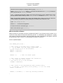
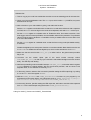
Listing for USART_Transmit and USART_TransmitUint8
9
Low Power and Embedded
Systems - Workbook 2
// Transmit an 8 bit value as is via serial
void USART_Transmit( unsigned char data ) {
while ( !( UCSR0A & (1<<UDRE0)) )
// Wait for empty transmit buffer
;
UCSR0A |= (1<<TXC0);
// clear txc flag
UDR0 = data;
// Put data into buffer, sends the data
}
// Transmit an unsigned 8 bit value as a series of up to three decimal characters
void USART_TransmitUint8(uint8_t val) {
unsigned char buf[3];
int8_t ptr;
for(ptr=0;ptr<3;++ptr) {
buf[ptr] = (val % 10) + '0';
val /= 10;
}
for(ptr=2;ptr>0;--ptr) {
if (buf[ptr] != '0') break;
}
for(;ptr>=0;--ptr) {
USART_Transmit(buf[ptr]);
}
}
Hardware: We are using an external VCC reference voltage, so we must connect AVCC to 5 V. It is safe
to connect a potentiometer from 5V to GND with the wiper connected to the analogue input. For stable
readings, AREF should be decoupled to ground with a 47nF or 100nF ceramic capacitor.
For a circuit diagram see connect_pot.pdf [http://www.cl.cam.ac.uk/teaching/0910/P31/docs/
connect_pot.pdf] and connect_pot.jpg
Program the device with your revised code, set the potentiometer to a middle position, and power
up the microcontroller.
Exercise 3 - Debugging
Things to consider when testing
1. Is the LED flashing? If not consider whether the program ever gets that far, or whether the program
is executing an endless loop in an interrupt service routine.
2. The loopback code is still in place, so pressing a key on the terminal should immediately echo it back
(check that it isn't local echo in Minicom).
3. If the result is always zero, does the potentiometer have a 5V supply ? You can check the
potentiometer voltage with a scope or multimeter. Is there a reference voltage present at Aref ? Are
you reading the correct input ?
4. If the result from the ADC doesn't change when you adjust the potentiometer, you may be reading
the wrong input. One test option would be to read the temperature sensor instead, see section 23.8,
but note that the voltage reference in this case should be the 1.1V internal one.
10
Low Power and Embedded
Systems - Workbook 2
5. If the result is always very low (0-3), you might have the result right adjusted, and only be seeing
the highest 2 bits of a 10 bit result. See section 23.9 for a description of the ADLAR bit in the register
ADMUX.
11
12