1
iRobot Command Module
®
Owners manual
www.irobot.com
Important Safety Instructions
GENERAL SAFETY INSTRUCTIONS
ePort SAFETY INSTRUCTIONS
•R
ead all safety and operating instructions before
operating iRobot Command Module.
The maximum voltage available on the ePor t is 21V, so
the ePort pins will not shock you if they contact your skin.
However, the ePort can supply over 20 watts of electrical
power. In the event of an electrical fault, this can generate
enough heat to burn you or start a fire in the event of an
electrical fault. Only experienced users should attempt to
design and build their own circuitry.Prebuilt ePort modules
are available from a supplier listed in the Appendix A and
are suitable for users who lack the experience to design
their own circuitry.
•R
etain the safety and operating instructions for
future reference.
• Follow all operating and use instructions.
• Refer all non-routine servicing to iRobot.
COMMAND MODULE USE RESTRICTIONS
• The Command Module is for indoor use only.
• Do not sit or stand on this device.
•K
eep the switch in the off position, otherwise the Create
robot battery will drain when iRobot Command Module
is on.
• Do not pour or spray water onto iRobot Command Module.
• Always use care when wiring custom circuitry to an ePort.
• Never run your iRobot Create unattended.
• Always fully test your new designs under close supervision.
•A
lways remove the battery from Create or remove the
ePort add-on circuitry from Create before handling it.
• D
o not expose iRobot Command Module to
anything hazardous, or anything that is burning
or smoking.
• Never touch the circuitry with the power turned on.
• iRobot Create has built-in safety sensors to keep it
from falling down stairs and bumping hard into walls.
iRobot is not responsible for any product issues that
may arise if you disable those sensors using the
Command Module.
• T he Vcc and Vpwr supplies are protected by a
self-resetting fuse within Create. If you exceed the
current ratings, power Create off for 30 seconds
to reset the fuse.
•E
nclose your add-on circuitry so it is not inadvertently
shorted during operation.
• Never handle the Command Module with wet hands.
•O
nly experienced users should attempt to design
and build their own circuitry.
iRobot Command Module Owner’s Manual
Table of Contents
Introduction............................................................................................5
1.1 Anatomy..........................................................................................5
1.2 Overview.........................................................................................5
1.3 Example applications.......................................................................5
2. Getting Started...................................................................................6
2.1 Plugging in the Command Module.....................................................6
2.2 Running the preinstalled “drive” demo program.................................6
2.3 Installing the development tools.......................................................7
2.4 Installing the USB serial port............................................................8
3. Your First Project................................................................................10
3.1 Developing for the Command Module................................................10
3.2 Setting up a new project...................................................................10
3.3 Compiling your project......................................................................11
3.4 Downloading your project over the USB link.......................................12
3.5 Testing the “input” example program.................................................13
3.6 Creating your own project.................................................................14
4. Software Reference.............................................................................15
4.1 Declaring and using variables and registers on the ATMega168..........15
4.2 I/O Pin Basics.................................................................................15
4.3 The Command Module’s connectors.................................................15
4.4 The Digital I/O control registers........................................................16
4.5 DDRx: Setting the direction of a pin...................................................16
4.6 PORTx: Setting pullups on an input pin..............................................16
4.7 PORTx: Setting the state of an output pin..........................................16
4.8 PINx: Reading the state of an input or output pin...............................16
4.9 Using bitwise operators to selectively change bit values.....................17
iRobot Command Module Owner’s Manual
4.10 Command Module Internal Pins......................................................17
4.11 Adding a button and LED to the input example program....................18
4.12 Taking an analog measurement using the ADC.................................18
4.13 Using an analog measurement in the light example program.............19
4.14 Using a timer.................................................................................20
4.15 Debouncing a Button Input.............................................................21
4.16 Setting up and using the serial port................................................22
4.17 Using the USB Port for Serial Debugging.........................................23
4.18 Powering Create............................................................................23
4.19 Putting the Command Module to Sleep............................................24
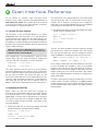
5. Open Interface Reference....................................................................25
5.1 Starting the Open Interface..............................................................25
5.2 Changing the baud rate....................................................................25
5.3 Controlling Create’s LEDs.................................................................26
5.4 Composing and playing songs...........................................................26
5.5 Moving Create.................................................................................27
5.6 Controlling Create’s low-side power drivers........................................27
5.7 Sending an Infrared Character..........................................................28
5.8 Reading Create’s sensors................................................................28
6.Microcontroller reference......................................................................29
7. Bootloader reference...........................................................................30
8. Hardware reference.............................................................................31
8.1 ePort Pinouts..................................................................................31
8.2 ePort I/O connections......................................................................31
8.3 ePort connection types and interfacing..............................................32
8.4 ePort electrical specifications...........................................................33
8.5 ePort safety and cautions.................................................................33
8.6 Component Suppliers.......................................................................34
iRobot Command Module Owner’s Manual
1
Introduction
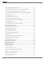
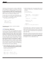
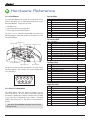
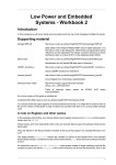
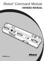
1.1 Anatomy
LED 1
LED 2
Hold Down Screws
Power LED
Power Switch
Top Left ePort
USB Indicator
USB
Soft Button
Reset
iRobot Create Connector
(under the Command Module)
Top Center ePort
Cargo Bay ePort
1.2 Overview
The iRobot Command Module works with iRobot Create,
giving you a way to write your own programs in C or C++
to control Create and to add custom hardware to expand
Create’s capabilities without tethering the robot to a PC.
The Command Module plugs into Create’s Cargo Bay
Connector, and it has four expansion ports that provide
additional inputs and outputs for your custom hardware.
Three of the connectors are on the top surface, spaced
to provide easy attachment points for an array of sensors,
and one connector is on the back for easy access from the
cargo bay.
The Command Module is powered by an Atmel AVR
ATMega168 microcontroller which can be reprogrammed
by downloading programs from your Windows XP computer
with the included USB cable. Your programs can use the
iRobot Open Interface serial protocol to control Create’s
motors, lights, and speaker, and read its sensors. At the
same time, the microcontroller can directly interface with
your own custom hardware through its I/O connections.
Start with one of the example programs and expand and
change it to add your own functionality. Updates and more
information are available at www.irobot.com/create.
This manual assumes intermediate knowledge of the C or
C++ programming languages, including bitwise operators.
If you don’t know either of these languages, pick up a book
on C from a library or bookstore. You can also find a lot of
good reference materials and tutorials online by searching
for “C language” in an internet search engine.
iRobot Command Module Owner’s Manual
Top Right ePort
The manual also assumes a basic familiarity with
microcontrollers, including I/O pins, registers, and
interrupts, as well as experience with compilers and
interactive development environments (IDEs).
For more information on how to use the Command Module’s
software capabilities, please see the Software Reference
chapter and the Open Interface reference guide found at
www.irobot.com/create.
1.3 Example applications
Whether you are a hacker, educator, or robotics hobbyist,
the Command Module opens many exciting possibilities.
The applications are limited only by your imagination:
• T each robotics and programming at high schools or
universities. iRobot Create is a robust, affordable
robotic platform that enables students to each have
their own robot.
•A
dd new sensors and carry out your own robotics
experiments.
•C
reate a low-cost swarm of robots to investigate
collective behavior.
•H
ave fun with robot “art” exhibits, song and dances or
other entertaining behaviors.
•A
dd a camera and internet connection to create a low
cost sentry robot.
2
Getting Started
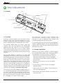
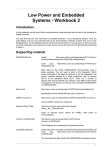
2.1 Plugging in the iRobot Command Module
2.2 Running the preinstalled “drive” demo program
Turn off Create.
The Command Module comes pre-installed with a demo
program to let you know that everything is working.
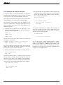
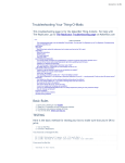
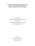
Plug the Command Module into the Create’s Cargo Bay
Connector as shown in Figure 1. Make sure it is firmly
seated.
Turn on Create and wait two seconds until Create’s Power
LED stops flashing, which indicates that Create is now
running its main code.
Press the “reset” button on the Command Module and
listen for a series of fast beeps. The LEDs on the Command
Module and Create will blink slowly.
Command
Module
Cargo Bay
Connector
iRobot Create
Create Figure 1 Inserting the Command Module into Create connector
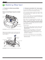
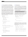
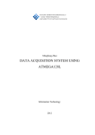
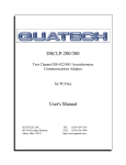
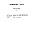
Tighten the two hold-down screws on either end of the
Command Module with a Phillips head screwdriver, as
shown in Figure 2.
Command Module
Hold-Down Screws
Philips-head
Screwdriver
Place Create on the ground and press the black “soft”
button on the Command Module. The robot will play
another song and then start driving around and flashing
its LEDs in sequence, beeping and turning when it bumps
into something. To stop the robot, press the “soft” button
again or pick the robot up.
Troubleshooting:
•A
fter turning on Create, always wait until Create’s Power
LED stops flashing rapidly before starting a Command
Module program.
• Make sure the Command Module is securely seated.
•M
ake sure that your iRobot Create has a full set of
charged batteries (see Create documentation for more
information on batteries).
• Disconnect the USB cable from the Command Module.
•E
nsure that Create’s serial cable is not connected to its
Mini-DIN connector.
Command Module
iRobot Create
Create Figure 2 Securing the Command Module with the hold-down screws
iRobot Command Module Owner’s Manual
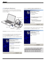
2.3 Installing the development tools
The development tools provided on the included CD-ROM
allow you to create your own Command Module programs.
The Command Module uses the WinAVR set of open-source
development tools to let you write your own programs in
the C or C++ languages. The development tools include
an editor, compiler, and a downloader for loading your
program onto the Command Module. For more information
on WinAVR, please check the project website at
http://winavr.sourceforge.net
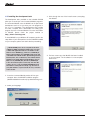
3. Click through the rest of the install screens, accepting
the defaults.
To install WinAVR on your Windows XP computer, perform the
steps below. If you have a previous version of WinAVR installed
on your computer, please uninstall it before proceeding.
NOTE: WinAVR places its access paths at the front
of Window’s PATH environment variable. This can cause
conflicts with application that use executables or dlls
that are also in WinAVR (e.g. make.exe; tclsh84.dll).To
fix this, after installing, move WinAVR’s paths to the end
of the PATH environment variable. Open Settings>Control
Panel>System, click on Advanced, click on Environment
Variables, Select Path under System Variables, click on
Edit, move C:\WinAVR\utils\bin and C:\WinAVR\bin
to the end of the list (after a semicolon), and click OK
3 times. On one occasion, installing WinAVR wiped out
the installer’s entire path. For safety, copy the value of
your path variable to a spare text file in case you need to
restore it later.
4. The last screen says that WinAVR has been installed
on your computer. The installation is now complete.
Click Finish.
1. Insert the Command Module product CD into your
computer. Start the WinAVR installation program
(WinAVR-20060421-install.exe) by double-clicking on it.
2. Select your language.
iRobot Command Module Owner’s Manual
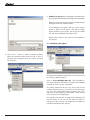
2.4 Installing the USB serial port
Select the Install the software automatically option
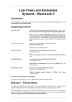
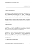
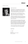
To install the drivers for the USB serial port, connect your
Command Module to your PC using the provided USB cable
as shown in Figure 3.
Included USB Cable
iRobot Create
USB Port on PC
USB Port on
Command Module
Command Module
It should install the driver and return without errors saying
that the hardware is installed and ready to use.
Create Figure 3 Connecting the Command Module to your computer’s USB port
The Command Module should be automatically detected
and the New Hardware Wizard window will pop up.
Select Yes to allow Windows to connect to Windows Update
to find the driver.
If the wizard says that it is unable to find the software,
quit the wizard and open the Command Module product
CD. Install the drivers manually by double-clicking on
CDM_Setup_32.exe (if you have 32-bit Windows XP) or
CDM_Setup_64.exe (if you have 64-bit Windows XP).
iRobot Command Module Owner’s Manual
The New Hardware Wizard window will then pop up a
second time, showing that it has found a USB Serial Port.
Repeat the above procedure, again selecting the Install the
software automatically option. Once the driver installation
has completed, click the Finish button and proceed to the
next step.
Next, find the COM port number which was assigned to
the Command Module.
On your PC, go to Start->Settings->Control Panel->System.
Go to the Hardware tab and click the Device Manager
button.
Scroll down and expand the Ports (COM & LPT) category by
clicking on the + sign.
Select the Port Settings tab and then click on the
Advanced button.
Double click on the USB Serial Port line to launch the
properties window.
Change the COM Port Number to COM9 or another unused
port between COM1 and COM9 using the pull-down menu.
Using a high port number will reduce the chances that the
port setting will interfere with other hardware that you may
install on your computer in the future. All of the example
programs assume that you are using COM9. If you use a
COM port other than COM9, you will need to update the
example program’s makefile before you download to the
Command Module. The installation is now complete.
iRobot Command Module Owner’s Manual
3
Your First Project
The example programs are a good place to start using the
Command Module. The program that came preprogrammed
on your Command Module is called drive and its source
code is in the “Sample Projects” directory on the Command
Module Product CD. This chapter will guide you through
compiling and downloading one of the other example programs
named input, and will then give you directions for creating
your own project. The input example program is designed
to demonstrate how to use all of the Command Module’s
input and output capabilities using buttons and LEDs.
3.1 Developing for the Command Module
The Command Module is built around an Atmel AVR
ATMega168 microcontroller. All of the programs that you
write and load onto the Command Module are run on this 8-bit
processor. For more information on the microcontroller,
please see the microcontroller reference section in chapter
7 and the microcontroller spec sheet on the Product CD.
3.2 Setting up a new project
In this example, you will set up a new project for the input
example program. The steps are similar for any new project
you create.
1. Get the source files. Make a new directory on your
computer and name it “input.” Copy the files input.c,
oi.h, and makefile from the examples/input directory
on the Command Module CD to this directory. The file
input.c is the main C source code file, oi.h is the Open
Interface header file, and makefile contains instructions
for Programmers Notepad on how to compile and
download the project.
The Command Module uses the WinAVR suite of open
source development tools to compile and download your
C or C++ programs. The WinAVR tools include the GNU
GCC compiler, avrdude downloader, and the Programmers
Notepad IDE.
2. Start Programmers Notepad using the desktop shortcut.
If you don’t have the shortcut, find Programmers Notepad
directly at C:\WinAVR\pn\pn.exe (if you used the
default installation directory)
The WinAVR installer installs a lot of useful documentation
in the C:\WinAVR\doc directory. In the avr-libc sub-directory
you’ll find the avr-libc user’s manual, which has information
on many functions designed for AVR microcontrollers which
you can use in your programs. Another good resource for
developing with AVR microcontrollers and using WinAVR in
particular is the avrfreaks website at http://www.avrfreaks.
net. One of the best sources of information on the website
is the forum, where you can find answers to most of your
development questions. Be sure to search the forum
before posting your own question because most common
questions have already been answered already.
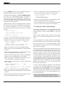
3. Create a new project. In Programmers Notepad, go to
File->New and click on Project.
iRobot Command Module Owner’s Manual
10
5. Add files to your project. Your new project should now show
up in the upper left-hand window of Programmers Notepad.
Right click on the name of the project under New Project
Group and select the Add Files option.
In the dialog box that opens, find your “input” project
directory, select the file input.c, and click the Open
button to add it to your project. The file you just added
will now show up beneath the project name.
Repeat these steps to also add oi.h and makefile to
your project.
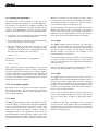
3.3 Compiling your project
4. Click on the … button to select the project directory
where you saved the project code (in step 1). Fill in a
name for your new project (such as “input”), and click
the OK button.
In Programmers Notepad, double-click on one of the source
files that you added to open it.
Click on Tools->[WinAVR] Make All. Text will appear in
the output window at the bottom of Programmers Notepad
showing the results of your compilation.
This output window will also list any errors and the line
numbers where they occur in your files. You should not get
any errors with the provided example programs, but errors
may occur as you develop your own code. If there are any
errors, fix them and compile again.
You can edit your text files in Programmers Notepad (see
the File menu), or you can use any other text editor to
change your files and just use Programmers Notepad to
compile and download your projects.
iRobot Command Module Owner’s Manual
11
3.4 Downloading your project over the USB link
The next step is to download your compiled hex file into the
Command Module. Before downloading, check that:
• The Command Module is turned on.
•Y
ou have pressed RESET on the Command Module to
force it to run its bootloader.
• There is a full set of charged batteries in Create.
•C
reate is turned on and its Power LED has stopped
flashing.
• Create’s serial cable is not plugged in.
• T he Command Module is securely seated on Create
cargo bay connector.
• T he Command Module is connected to your computer
with the supplied USB cable and you have installed the
USB serial port drivers as described in 2.4.
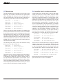
When your compilation is successful, the size of your
compiled file in bytes will be listed toward the bottom of
output window on the line labeled .text (outlined in the
picture above - your statistics may be slightly different). The
maximum size program that fits in the Command Module’s
flash memory is 14336 bytes (7168 words). The top 1024
words of the flash memory are taken up by the bootloader
and can’t be used.
• T he COM port of your Command Module matches the
COM port listed in the makefile. The example programs
assume you are using COM9. If you installed your
Command Module on a different port number, update
your makefile. Open the makefile in a text editor and
search for where the variable AVRDUDE_PORT is set (on
line 204 in the input project makefile). Change the value
from COM9 to your desired port number, for example:
AVRDUDE_PORT = com4
serial device
# programmer connected to
When your compilation is successful, it creates a hex file
(input.hex in this case) in your project directory that you
can load into the Command Module.
Sometimes, when developing your own code, the compilation
may not work even though you think it should. To make
sure that no intermediate files generated by the compiler
are causing a problem, click on Tools->[WinAVR] Make
Clean, and then try compiling again.
TIP: If avrdude says “cannot find the file specified”, check
that you have the correct COM number, and check all
connections.
TIP: If avrdude says “not in sync: resp=0x00”, press reset
before downloading.
Always press Reset on the Command Module before
downloading.
iRobot Command Module Owner’s Manual
12
Press the RESET button on the Command Module with the
USB cable attached to start the bootloader.
In Programmers Notepad click on Tools-> [WinAVR] Program.
This star ts the downloading program “avrdude”. It
communicates with the Command Module’s bootloader to
erase the Command Module’s flash memory and then write
in your new program. This process can take up to a couple
of minutes for a large program.
Avrdude outputs its status in the debug window as it erases
the memory and then writes and verifies your new program.
On successful completion, you will see text similar to
the following toward the bottom of the text in the debug
window:
avrdude: verifying ...
avrdude: 2118 bytes of flash verified
avrdude done.
Thank you.
If it doesn’t successfully program, and you get an error
message similar to the ones listed below, follow the
suggestions that follow to fix the problem and try again.
avrdude -p ATMega168 -P com9
-U flash:w:input.hex
-c stk500
avrdude: ser_open(): can’t open device “com9”:
The system cannot find the file specified.
• Make sure Create has a full set of charged batteries.
•M
ake sure that the Command Module is securely seated
in Create.
•M
ake sure that the USB cable is firmly plugged into both
the Command Module and your computer.
•M
ake sure that the COM number of the Command Module
matches the com number listed in your makefile.
•M
ake sure that you installed the USB serial port for your
Command Module as described in chapter 2.
•M
ake sure that no other device is using the COM number
in the makefile.
avrdude -p ATMega168 -P com9
-U flash:w:input.hex
-c stk500
avrdude: stk500_getsync(): not in sync: resp=0x00
• Make sure Create has a full set of charged batteries.
•M
ake sure that the Command Module is securely seated
in Create.
•M
ake sure that the USB cable is firmly plugged into both
the Command Module and your computer.
iRobot Command Module Owner’s Manual
•P
ress the reset button on the Command Module, being
sure not to press the soft button at the same time.
avrdude -p ATMega168 -P com9
-U flash:w:input.hex
-c stk500
…but then nothing happens.
•M
ake sure that the USB cable is firmly plugged into both
the Command Module and your computer.
•P
ress the reset button on the Command Module, being
sure not to press the soft button at the same time.
3.5 Testing the “input” example program
Remove the USB cable from the Command Module. Make
sure Create’s serial cable is not plugged in. Press the
red Reset Button on the Command Module to start your
program.
When the input program starts, two LEDs should flash
slowly, one on the Command Module and one on Create
itself.
Press the Play button on Create. It will play a song and light
the Advance LED on Create solid while the song is playing.
Press the soft button on the Command Module. Create
plays a different song and the LED on the Command Module
stays lit while it’s playing.
There are three different input/output methods you can use
in your programs, two of which you’ve just seen. First, you
can read the state of Create’s buttons and other sensors
and set the state of its LEDs and motors using the Open
Interface serial protocol. Next, you can interact with the
Command Module’s built-in hardware by reading the state
of the soft button or controlling LED 1 and LED 2 on the
Command Module. Finally, you can add your own hardware
for input and output. The next chapter will walk you through
adding another button and LED to one of the Command
Module’s input/output (I/O) ports and interacting with
them with the input program.
A note on starting programs. Normally, if the USB cable
is inserted in the Command Module when you press the
reset button, the Command Module runs its bootloader
and does not start your program. To run your program
without first removing the USB cable, press and hold down
the programmable button on the Command Module as you
press the reset button.
TIP: To run your program with the USB cable attached,
hold down the soft button while pressing the reset button.
13
3.6 Creating your own project
The easiest way to start a project is to copy one of the
example programs and modify it for your own application.
For instance, the framework for sending commands and
reading sensors provided by the drive example can be
useful for most applications. To create your own project
based on the drive example, perform the following steps:
1. Copy drive.c, oi.h, and makefile from the drive example
directory over to your new project directory.
2. In the new directory, rename drive.c to the desired name
for your new program, such as myapp.c
3. Edit the makefile to reflect the new name of your
application. Specifically, you need to change the value
of TARGET to the name of your new application. On line
59 of the drive makefile, you’ll see the line:
TARGET = drive
Change this to the new name of your application.
For instance:
TARGET = myapp
Next, change the behavior of the program to suit your new
application by changing the C code. In drive.c, the behavior
of Create is defined in the main function. Refer to chapters
5 and 6 for examples of the different functionality that you
can add. When you’re ready with your code, repeat all of
the steps in this chapter to set up a project and to compile,
download, and test your program.
3.6.0 The example programs
By looking at the source code of the example programs,
you can get a sense for the kind of code you can write for
the Command Module. Below is a brief description of the
three example programs.
3.6.1 Drive
The drive example program comes preprogrammed into the
Command Module. It demonstrates the basic capabilities
of the Command Module and the iRobot Create Open
Inter face by driving around, reacting to sensors, and
using various inputs and outputs. It makes a series of
rising beeps when it is first powered to let you know the
Command Module is alive and blinks Create’s LEDs (note
that the program makes Create’s power LED orange). Then,
if you place Create on the floor and press the Command
iRobot Command Module Owner’s Manual
Module’s soft button it starts driving on the floor, backing
up and turning when it runs into something with its bumper,
and blinking all LEDs in a pattern. To stop the program,
press the button again or simply pick it up.
The code provides useful function to initialize the Command
Module and iRobot Create, continuously read Create’s
sensor values, drive Create, turn on Create, and change the
baud rate. You can add capabilities to the main function of
the program using the software examples in chapter 5.
3.6.2 Input
The input example program illustrates the three types
of input and output that you can use with the Command
Module. You can interact with hardware on iRobot Create
through the Open Interface, use the built-in Command
Module hardware, and add your own hardware to the
Command Module’s connectors.
This simple program flashes three LEDs, one on each type
of output, and waits for button presses on each type of
input. If it gets a button press, it lights the associated LED
and plays a song.
Add your own button and LED, as described in chapter 4,
and try using all three types of input and output.
3.6.3 Light
The light example program demonstrates a possible
application for the Command Module and iRobot Create. It
searches your house for lights which are left on and plays
an alarm when it finds a light so that you can turn it off. The
program has all of Create’s and Command Module’s LEDs
turned on (note that Create’s power LED will be orange) so
that it’s easy to find in the dark.
Start it up in a relatively dark room by pressing the soft
button. It will sample the light level when it starts and will
set off its alarm when it detects a significantly brighter
room.
To detect the light level, the program uses a CDS light
sensor which you need to add to the Command Module’s
top center ePort, as described in section 4.12. It measures
the light level from the sensor using one of the Command
Module’s analog input pins.
14
4
Software Reference
This chapter gives code examples and explanations of how
to control some of the Command Module’s hardware. For
full details on the ATMega168’s registers and features,
please see the ATMeta168 datasheet, included on the
product CD.
To make it even more convenient, you can use the bit value
macro _BV as shown below:
4.1 Declaring and using variables and registers on
the ATMega168
The Command Module gives you direct access to the
Atmel ATMega168 microcontroller’s input/output (I/O)
pins, so you can add any control signals, sensor drivers, or
communication protocols necessary to interface with your
external hardware.
The processor in the Command Module is an Atmel
ATMega168 8-bit microcontroller. All of the operations
on the processor are carried out with 8-bit registers (as
opposed to the 32-bit registers in most home computers).
For efficiency, use 8-bit variables and calculations wherever
possible, only using 16-bit variables wherever their greater
range is really necessary.
Do not use floating point numbers or division in your
Command Module code. The ATMega168 doesn’t have
hardware to handle floating point numbers or divide
operations. If you use these, your compiled code gets big
very fast. Instead, use integers, and use right shifts (>>)
instead of divides.
The example programs use explicit type notation so that
you can easily tell the size of a variable. This notation is
recommended for all of your own code. The example code
declares variables with the following types:
uint8_t variable_a;
/* unsigned 8-bit variable */
int8_t variable_b;
/* signed 8-bit variable */
uint16_t variable_c; /* unsigned 16-bit variable */
int16_t variable_d;
/* signed 16-bit variable */
To use these variable types, include the stdlib.h file at the
beginning of your program:
#include <stdlib.h>
The microcontroller’s built-in registers (e.g. DDRB, PORTC,
PIND referenced below) are all declared in header files
which are installed with WinAVR. Include the following line
at the beginning of your program:
#include <avr/io.h>
This header also declares the bit value for all named bits in
the ATMega168 datasheet. So, you can use lines like the
following in your code:
UCSR0B |= (1 << RXEN0); /* Set the RXEN0 bit in
UCSR0B */
iRobot Command Module Owner’s Manual
UCSR0B |= _BV(RXEN0);
4.2 I/O Pin Basics
The following sections explain how to use the I/O pins and
then gives an example of adding an extra button and LED to
the input example program. Another section explains how
to use an analog input to measure the voltage of a light
sensor using the light example program.
The Command Module provides digital input and output
pins, as well as analog input pins. The Command Module
uses 5V logic and a 5V reference for the analog inputs.
Full technical details on the Command Module’s Atmel
ATMega168’s I/O pins and registers can be found in the
microprocessor reference manual, included on the CD.
4.3 The Command Module’s connectors
The microcontroller’s I/O pins are connected to the
Command Module’s four ePorts. There are three ports on
the top and one on the side facing the cargo bay. The top
three connectors are positioned so that you can attach
sensors on the right, left, and center and compare their
values to steer the robot.
TIP: If you attach a light sensor to the analog input of
each top connector, you can program iRobot Create to
follow a flashlight by turning toward the sensor that
receives the most light.
The Cargo Bay ePort has extra I/O lines for Create’s Low
Side Drivers, which you can use to run motors without
any additional hardware. For a complete list of all of the
Command Module’s I/O and connectors, refer to the
Hardware reference section in chapter 9.
Some of the I/O pins are connected to the Create CargoBay
Connector, located on the underside of the Command
Module.
15
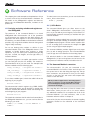
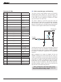
4.4 The Digital I/O control registers
4.6 PORTx: Setting pullups on an input pin
The Command Module’s ATMega168 microcontroller has
three I/O ports, labeled B, C, and D. Each of these ports
contains 8 pins, numbered 0 to 7. The Command Module’s
ePorts expose pins B 0-3 and C 0-5. See the Hardware
Reference in chapter 8 for a table of which microcontroller
pins are connected to which ePort pins.
Register: PORTx
0 = pull-up disabled
1 = pull-up enabled
The digital I/O pins on each port are controlled and
accessed by three built-in registers per port. You need to
set the value of some of these registers before using the
I/O pins. The registers are predefined as 8-bit variables in
the <avr/io.h> header file which is installed with WINAVR.
The I/O registers are summarized in the table below and
more information on setting their values is included in the
sections that follow.
DDRD = 0x01; // enable pull-up on pin B0 only
For an input pin, a bit value of 1 in the PORTx register
enables a pull-up on that pin; a bit value of 0 disables the
pull-up. If the pin is an input with the pull-up enabled, it is
guaranteed to be in the high state if it is not being driven
low by external hardware. If the pull-up is not enabled
on an input pin and it is not being driven, then the pin is
considered to be floating and you can’t depend on it being
in a specific state.
4.7 PORTx: Setting the state of an output pin
DDRB
Port B direction register. Bit values: 0 = input, 1 = output.
DDRC
Port C direction register. Bit values: 0 = input, 1 = output.
DDRD
Port D direction register. Bit values: 0 = input, 1 = output.
PORTB
Port B data register. Output bit values: 0 = low, 1 = high.
Input bit values: 0 = pull-up disabled, 1 = pull-up enabled.
PORTC
Port C data register. Output bit values: 0 = low, 1 = high.
Input bit values: 0 = pull-up disabled, 1 = pull-up enabled.
PORTD
Port D data register. Output bit values: 0 = low, 1 = high.
Input bit values: 0 = pull-up disabled, 1 = pull-up enabled.
PINB
Port B input register. Bit values: 0 = pin is low,
1 = pin is high.
PINC
Port C input register. Bit values: 0 = pin is low,
1 = pin is high.
PIND
Port D input register. Bit values: 0 = pin is low,
1 = pin is high.
4.5 DDRx: Setting the direction of a pin
Register: DDRx
0 = input
1 = output
The DDRx registers (substitute B, C, or D for the x) control
the direction of the eight pins in a port. If the bit associated
with the pin is set to a 0, then that pin is an input (for
example, a sensor or button); if it’s a 1, then it’s an output
(for example, a motor or LED). These registers must be set
before using the PORTx and PINx registers.
Example: Set pins C0 – C2 as inputs and C3 – C7 as outputs:
DDRC = 0xF8;
Register: PORTx
0 = low (0 volts)
1 = high (5 volts)
DDRB = 0x10; // set pin B4 (already an output)
to high
The PORTx register sets the state of an output pin, either
high or low. If the pin’s bit is set as a 0, then that pin will be
low (0 volts); if it’s a 0, then it will be high (5 volts).
Note that when a pin is an output, the PORTx register
specifies its state, but when it is an input, the PORTx
register specifies whether its pull-up in enabled.
To change the state of one pin at a time while leaving
the other states undisturbed, use C’s bitwise operators.
Section 4.9 below gives examples of this.
4.8 P
INx: Reading the state of an
input or output pin
Register: PINx
0 = low (0 volts)
1 = high (5 volts)
The PINx registers are used to read the state of the pins,
either high or low. If a pin is low, the associated bit in the
register will read as a 0; if it is high, it will read as a 1.
You can read the state of a pin whether it is an input or an
output.
The hexadecimal (hex) value 0xF8 = 11111000 in binary,
so the most significant 5 pins (C3 – C7) become outputs.
iRobot Command Module Owner’s Manual
16
4.9 U
sing bitwise operators to selectively
change bit values
The C bitwise operators, bitwise-or (|=), bitwise-and (&=),
and bitwise-exclusive-or (^=), as well as the not operator
(~) should be used to change the value of one bit at a time
with these registers. Some examples are below.
The following code sets pin B2 as an output:
DDRB |= 0x04;
This sets the value of bit 2 to be 1, but doesn’t affect the
other bits in DDRB. The following code sets pin D7 as an input:
DDRD &= ~0x80;
This sets bit 7 in DDRB to be a 0 without affecting the other bits.
4.10 Command Module Internal Pins
The Command Module’s ePorts only expose pins B0-B3
and C0-C5. See the Hardware Reference in chapter 9 for
the details and locations of these pins on the ports. The
remaining pins are reserved for the Command Module’s
own hardware and the Create Cargo Bay Connector on the
underside of the Command Module:
Pin
Description
Direction
PB4
Serial port select. 1 = connect serial I/O to USB
port. a0 = connect serial I/O to Create
Output
PB5
Create Power Detect. High if Create is on.
Input
PD0
Serial Rx
Input
PD1
Serial Tx
Output
PD2
Create Device Detect Input. Change Create’s baud
rate to 19200 by toggling this pin 3 times with 200
ms pulses (or use the Baud command - see the
Open Interface documentation)
Output
PD3
USB Detect
Input
PD4
Command Module Soft Button
Input
PD5
Command Module LED 1
Output
PD6
Command Module LED 2
Output
PD7
Create Power Toggle. Turn Create on or off with a
low-to-high transition.
Output
Once you’ve set pin B2 as an output, the following code
sets its state to high:
PORTB |= 0x04;
The following code sets pin B2 low:
PORTB &= ~0x04;
If you just want to flip the state of the pin (low to high or
high to low), you can use the bitwise-exclusive-or operator.
The following code flips the state of pin B2:
PORTB ^= 0x04;
To check whether a pin is high or low, read the PINx register
and then use the bitwise-and operator to check only the
associated bit. The following code branches your code
according to the state of pin D7:
For these pins, only use the direction stated in the table
above. The remaining pins (B6-7, C6-7) are for Command
Module internal use only. Their direction is set in hardware
and cannot be changed with software.
if(PIND & 0x80) {
/* if D7 is high, run this code */
}
else {
/* otherwise, if D7 is low, run this code */
}
If D7 was connected to a button, you could use this code to
perform different actions depending on whether the button
was being pushed.
iRobot Command Module Owner’s Manual
17
4.11 A
dding a button and LED to the input
example program
4.12 T
aking an analog measurement
using the ADC
In chapter 3, you saw that the input example program
looks for button presses on Create and on the Command
Module and plays a song and lights an LED when a button
is pressed. The program is also looking for button presses
on a top center ePort input pin and setting an ePort output
pin to drive an LED.
The I/O pins on PORTC of the Command Module can be
used to take analog measurements with the processor’s
10-bit Analog-to-Digital converter (ADC). For full details on
the ADC, see the “Analog to Digital Converter” section of
the processor datasheet, included on the Product CD.
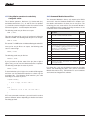
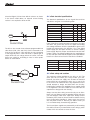
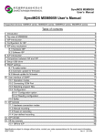
Buy a standard pushbutton and an LED from one of the
sources listed in Appendix A. Solder them onto a male DB-9
connector as shown in Figure 4. The button is connected to
pin 3 (B1) and pin 5 (GND), and the LED is connected to pin
2 (C1) and pin 4 (5V), with the flat side toward pin 2 and the
longer lead connected to pin 4. This makes the LED active
low (lit when low).
ADC reading = Vin * 1024 / Vref = 1 V * 1024 / 5V = 205
To take an analog measurement, you need to set up the
ADC, start the measurement, and then store the result
when it is done. Each of these operations uses registers
which are predefined in the WINAVR environment in the
<avr/io.h> header.
LED
Longer leg of LED
The 10-bit ADC uses a 5V reference, so the result of an
analog measurement on the Command Module is an
unsigned 10-bit number with a value from 0 to 1023,
representing input voltages from 0 V to 5 V. For instance,
an input voltage of 1 V gives you an ADC reading of 205
according to the formula:
Flat side of LED
1. Set up the ADC. The following code uses predefined
registers to set the processor up to take analog
measurements on pins C4 and C5 (located on pin1 of
the Cargo Bay and top center ePorts respectively):
Pin 4 (5 VDC)
Button
DDRC &= ~0xC30;/* set C4, C5 as inputs */
Back side of male
DB9 connector
DIDR0 |= 0x30; /* disable digital input on C4, C5 */
PRR &= ~0x01;
/* disable ADC power reduction */
ADCSRA = 0x87; /* enable ADC, prescale = 128 */
Pin 3 (B1)
Pin 2 (C1)
Create Figure 4 Button and LED assembly for the input example program
Plug this assembly into the top center ePort. Install the
Command Module in Create. Reload the input example
program onto the Command Module if necessary and
restart it by removing the USB cable and pressing the
Command Module’s reset button. You should notice three
LEDs flashing, including the one on the assembly you just
installed. If you press the button on your assembly, the input
program will light the LED solid and play a third song.
ADMUX = 0x40;
/* set voltage reference */
The first line above sets up pins C4 and C5 as inputs. The
second line disables the digital inputs on these pins to
save power when you only want to use them as analog
inputs. The third line turns off a power-saving feature that
can’t be used when using the ADC. The fourth line enables
the ADC and sets the ADC prescaler to a value of 128 in
order to slow down the clock that controls the ADC so that it
functions properly while still allowing the main processor to
run at a faster frequency. The last line sets up the voltage
reference to be the internal processor pin AVcc, which is 5V
in the Command Module.
The next step is to set up some variables to store the result
of the measurements. The following code declares two
16-bit variables (needed to store the 10-bit ADC results):
uint16_t meas_c4;
uint16_t meas_c5;
iRobot Command Module Owner’s Manual
18
2. Select the channel as C4 and take the first measurement:
ADMUX &= ~0x0F;
/* clear the ADC channel */
ADMUX |= 0x04;
/* set the ADC channel to C4 */
ADCSRA |= 0x40;
/* start the ADC measurement */
while(ADCSRA & 0x40); /* wait until it’s done */
meas_c4 = ADC;
/* save the result */
The low 4 bits of the ADMUX register let you select which
pin to read from (C0 – C7). So the first two lines of the
code clear the ADC channel and then set it to a value of
4 for pin C4. The third line sets bits 6 in ADCSRA, which
starts the ADC measurement. The while loop on the next
line waits until the measurement is complete by watching
the ADSC bit in the ADCSRA register, which goes to 0 when
the measurement is done. The 10-bit result is then stored
in a 16-bit variable on the last line. ADC is a predefined
16-bit register.
Now, to take a measurement on pin C5, repeat the process
with the channel set to 5:
ADMUX &= ~0x0F;
/* clear the ADC channel */
ADMUX |= 0x05;
/* set the ADC channel to C5 */
ADCSRA |= 0x40;
/* start the measurement */
4.13 Using an analog measurement in the
light example program
The light example program demonstrates a possible
application for the Command Module and iRobot Create.
With this program, Create searches your house looking
for lights that have been left on so that you can turn
them off.
Start it up in a dark room by pressing the soft button.
It takes a light measurement when it first starts (to calibrate
the sensor) and when it finds an area with significantly more
light, it stops and beeps so that you can locate it and turn
off the light.
The light example program uses the ADC to measure the
analog voltage from a CDS light sensor. When more light
hits the CDS sensor, you will measure a higher voltage
at the ADC input, and vice versa. The example program
then uses this information to search for and identify lights
left on.
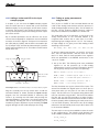
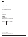
To try the light example program, you need to make your
own light sensor. Buy a CDS light sensor, a 10 K resistor,
and a male DB-9 connector to allow you to easily plug the
sensor into the Command Module. Please see Appendix A
for several sources where you can buy these components.
Once you have the components, assemble them as shown
in Figure 5.
while(ADCSRA & 0x40); /* wait until it’s done */
meas_c5 = ADC;
CDS Light Sensor
/* save the result */
The 10-bit analog voltage measurements from pins C4 and
C5 are now stored in the 16-bit variables and can be used
for any calculations or decisions in your program.
Pin 4 (5 VOC)
Pin 5 (Gnd)
Pin 1 (C5)
The ADC can also be set up to trigger an interrupt when
it is complete if you don’t want your program to have to
wait while taking the measurement. Please refer to the
ATMega168 datasheet and the avr-libc documentation for
more information on setting up an ADC interrupt.
10K Transistor
Create Figure 5 Light sensor assembly for the light example program
iRobot Command Module Owner’s Manual
19
Your light sensor is now ready to use. Insert it into the top
center ePort.
Now, create a new project, build the light example program,
and download it into the Command Module using the
process explained in chapter 3. Download the latest source
files from www.irobot.com/create.
Look through the code to see that the program takes one
ADC measurement when it first starts in order to set a
baseline light measurement. Then, it continuously measures
the light level in the main loop of the program while running
and compares the current value with the baseline. You
can set off the alarm early by shining a flashlight on the
light sensor. Try running the light example program and
changing some of the parameters to see how it changes
the behavior.
4.14 Using a timer
The fourth line of the code enables the timer interrupt. See
the ATMega168 datasheet for more information on these
control registers.
2. Declare variables to store the current count of the timer
and also a flag variable to let you know when the time has
expired. The timer counter should be a 16-bit variable
to allow you to specify longer times (up to 65.535
seconds). You can use this variable to determine when
a certain number of interrupts have elapsed. Declare
the variables with the following code:
volatile uint16_t timer_cnt = 0;
volatile uint8_t timer_running = 0;
3. Define the actual interrupt handler function code. This
code will get called by the microcontroller once per
millisecond as specified by the timer registers above.
SIGNAL(SIG_OUTPUT_COMPARE1A)
{
You can use timers to control Create’s motions, generate
signals, or time events. This section will show you how to
set up a countdown timer with 1 millisecond (ms) accuracy
using one of the ATMega168’s timer interrupts. This section
assumes basic familiarity with microprocessor interrupts.
if(timer_running)
{
if(timer_cnt)
timer_cnt--;
else
The frequency of the processor in the command module is
18.432 MHz.
1. Set up an interrupt to occur once every millisecond.
Toward the beginning of your program, set up and enable
the timer1 interrupt with the following code:
TCCR1A = 0x00;
TCCR1B = 0x0C;
OCR1A = 71;
TIMSK1 = 0x02;
The first two lines of the code put the timer in a mode in
which it generates an interrupt and resets a counter when
the timer value reaches the value of OCR1A, and select
a prescaler value of 256, meaning that the timer runs at
1/256th the speed of the processor. The third line sets
the reset value of the timer. To generate an interrupt every
1ms, the interrupt frequency will be 1000 Hz. To calculate
the value for OCR1A, use the following formula:
OCR1A = (processor_frequency / (prescaler *
interrupt_frequency)) - 1
OCR1A = (18432000 / (256 * 1000)) - 1 = 71
iRobot Command Module Owner’s Manual
timer_running = 0;
}
}
The first line declares that this is the handler function for
the timer1A compare interrupt in the form that the AVR
compiler expects. See the avr-libc documentation that came
with WinAVR for information on how to declare other types
of interrupt handlers. The body of the interrupt checks to
see if the timer is running, and if it is running it reduces the
timer counter by 1. When the timer counter has counted
down to 0, it sets the timer_running variable to false (0).
You can now put timed delays into your Command Module
programs. The following code allows you to do something
for 2 seconds and then stop:
timer_cnt = 2000;
timer_running = 1;
while(timer_running)
{
/* add code here to do something while you wait */
}
20
The first line of the code sets the counter to 2000 which
sets the delay time to 2000 ms or 2 seconds. The second
line sets the timer_running flag variable to true (1) so that
you can then watch it in a while loop on the third line. When
the flag variable becomes false, you know that the time has
elapsed. You can add code in the body of the while loop to
perform while you are waiting for the delay to end.
2. Add the following code in your program where you are
looking for a button press. It will debounce the button
for 50 ms:
button_pressed = 0;
while(!button_pressed)
{
if(PINB & 0x02)
In some cases, you just want to wait until the delay is over.
For that purpose, you can define a simple delay function
that just waits for a specified period of time:
/* check the button */
button_cnt = 0; /* if not pressed */
else
button_cnt++;
void delayMs(uint16_t time_ms)
/* if pressed */
{
if(button_cnt >= 50)
timer_cnt = time_ms;
button_pressed = 1;
timer_running = 1;
while(timer_running) ;
}
This delayMs function above is used in the included
software examples.
4.15 Debouncing a Button Input
In some cases you’ll want to filter the digital inputs instead of
using them directly. The filtering will depend on the specifics
of the hardware connected to the input but one common
example is debouncing a button. When a button directly
connected to an input pin is pressed, the input signal will
often “bounce” between high and low before settling down
into the correct state. This can be a problem, particularly
if you are counting the number of button presses. Instead
of counting every transition, you only want to consider the
button as pressed once it has settled down. To add this
type of filtering to the button, you’ll want to keep sampling
the input periodically and only consider the button pressed
once it has been in the pressed state continuously for a
certain number of samples. For a button input, debouncing
for 50 milliseconds (ms) is plenty of filtering.
delayMs(1);
/* delay for 1 ms using timer function */
}
The code above waits in a while loop, counting the number
of times that the button input is low. Since there is a 1ms
delay in the loop, each increment of button_cnt represents
1 ms of time. Section 4.14 describes how to implement the
delay functionality.
When button_cnt reaches 50, the input has been continuously
low for 50 ms and can be considered “pressed”. If the button
is ever high, the counter is reset so that the debouncer will
reject any short pulses. You can add this or similar code to
your programs to ensure reliable button input.
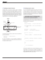
1. Toward the beginning of your program, set up the input pin
(B1 in this example) and declare the variables needed.
Connect the button between B1 and ground. Then when
the button is pressed, B1 will go low.
uint8_t button_pressed = 0;
uint8_t button_cnt = 0;
DDRB &= ~0x02; /* make B1 an input */
PORTB |= 0x02; /* activate B1 pull up*/
iRobot Command Module Owner’s Manual
21
4.16 Setting up and using the serial port
To control Create, you communicate with it through the
Open Interface serial protocol. In order to do that, you need
to set up and use the Command Module’s serial port.
3. To receive a byte over the serial port, wait for a byte to be
available and then read the byte from the serial receive
buffer. The following code combines these operations
into a function called byteRx:
uint8_t byteRx(void)
Note that Create requires that data sent at its highest baud
rate (115200) be sent a minimum of 200µsec apart.
{
This requires using registers that are defined in the
<avr/io.h> header that is included with WinAVR. See the
processor datasheet on the CD for more details on the
serial port registers.
/* wait until a byte is received */
1. Configure the serial por t at the beginning of your
program. The following code sets up the serial port to
communicate at 57600 baud:
UBRR0 = 19;
UCSR0B = 0x18;
while(!(UCSR0A & 0x80)) ;
return UDR0;
}
This function will wait until it receives the next byte, so
don’t call it unless you know a byte is being sent or you
could end up waiting forever. You can check if a byte is
available with the following code:
if(UCSR0A & 0x80)
{
UCSR0C = 0x06;
The first line of the code above selects the baud rate
according to the formula:
UBRR0 = (processor_frequency / (16 * baud_rate)) – 1
UBRR0 = (18432000 / (16 * 57600)) – 1 = 19
Also see ”Changing the baud rate,” below. The second line
enables the transmit and receive functions of the serial
port and the third line selects 8-bit data.
/* a serial byte is available */
}
You can also set up a serial receive interrupt to receive
bytes in the background and store them for you to look
at later in your program. The drive example program uses
this method to receive sensor information from the Open
Interface. You can copy this functionality by adapting your
program from the drive example.
2. To send a value over the serial port use code such as:
while(!(UCSR0A & 0x20)) ;
UDR0 = 128;
The first line above waits in a while loop until the serial
transmit buffer is empty, and the second line loads the
value to be sent (128, in this example). These operations
can be combined into a function named byteTx which will be
used in the rest of the software examples in this chapter:
void byteTx(uint8_t value)
{
while(!(UCSR0A & 0x20)) ;
UDR0 = value;
}
iRobot Command Module Owner’s Manual
22
4.17 Using the USB Port for Serial Debugging
4.18 Powering Create
The Command Module processor only has one UART (serial
hardware device), but it can be directed either to the Create
connector or to the USB serial connector. Sometimes you
may want to debug your program by sending characters to
the PC, or sending characters to the module from your PC.
You can turn Create’s power on or off through the digital I/
O lines of the Command Module. If you have an application
that requires long periods of waiting you can turn off Create
and just run the Command Module in order to conserve
battery power. At a certain sensor event or after a given
amount of time, you can turn Create back on and proceed.
You can also shut down Create at the end of your programs
to avoid draining the batteries.
Pin B4 is connected to a device that can switch the UART
from Create to the USB connector. Make sure that this pin
is always configured as an output. If B4 is high (1), the
UART is connected to the USB. If B4 is low (0), the UART
is connected to the Create connector. After changing the
destination of the UART, wait for at least 10 bit times at
your chosen baud rate before attempting to send or receive
data. For example, at 57600 baud, wait for at least 10 /
57600 seconds, or 174 microseconds. The following code
provides some useful functions for sending characters out
of either the USB or Create port:
#define USB 1
#define CR8 2
void setSerial(uint8_t com) {
if(com == USB)
PORTB |= 0x10;
else if(com == CR8)
PORTB &= ~0x10;
}
uint8_t getSerialDestination(void) {
if (PORTB & 0x10)
return USB;
else
return CR8;
}
void writeChar(char c, uint8_t com) {
uint8_t originalDestination = getSerialDestination();
if (com != originalDestination) {
Always check that Create is on, and then wait at least
2 seconds for Create to finish running its bootloader
before attempting to communicate with Create.
To detect whether Create’s power is currently on, set up
the Create Power Detect pin (B5) as an input, with the pullup disabled. If this pin is high, Create’s power is on. The
following code detects whether Create’s power is on:
DDRB &= ~0x20;
PORTB &= ~0x20; /* disable pull-up */
if(PINB & 0x20)
{
/* iRobot Create power is on */
}
else
{
/* iRobot Create power is off */
}
To toggle iRobot Create’s power on or off use the Create
Power Control pin (D7). The robot’s on/off state will toggle
whenever there is a low to high transition on D7. The
following code detects whether Create’s power is on and
turns it on if it’s not:
DDRD |= 0x80;
{
PORTD &= ~0x80;
PORTD |= 0x80;
}
setSerial(originalDestination);
/* set D7 low */
delay(100); /* delay so new state is seen by Create */
delayus(200);
if (com != originalDestination) {
/* make D7 an output */
if(!(PINB & 0x20)) /* if power is off */
setSerial(com);
byteTx((uint8_t)(c));
/* make B5 an input */
delay(100);
/* set D7 high to turn power on */
/* delay so new state is seen by Create */
}
delay(2000);
/* Wait for Create’s bootloader to run */
delayus(200);
}
}
iRobot Command Module Owner’s Manual
23
PORTC = 0x7F; // enable pull-ups on all C pins
The 100 ms delays are included in the code above so that
fast transitions aren’t missed by Create. The following code
turns off Create’s power:
DDRD = 0xEE;
// D0 (rx) and D4 (button) are inputs
PORTD = 0x78; // configure D pins
if(PINB & 0x20) /* if power is on */
// Put the command module into sleep mode
{
// These functions are defined <in avr/sleep.h>
PORTD &= ~0x80; /* set D7 low */
set_sleep_mode(SLEEP_MODE_PWR_DOWN);
delay(100);
sleep_mode();
/* delay so new state is seen by Create */
PORTD |= 0x80;
delay(100);
/* set D7 high to turn power off */
}
/* delay so new state is seen Create */
}
4.19 Putting the Command Module to Sleep
The Command Module processor has a low-power sleep
mode. You can put the module into this mode to conserve
power without having to remove it from Create or turn it off.
Create’s battery power is always available to the Command
Module so the Command Module can drain Create’s
batteries if it is left in the robot. The following code puts
the processor into low power mode after first turning off
Create, and setting all of the Command Module pins and
other hardware into the state that draws the least power:
#include <avr/sleep.h>
void powerOff(void)
{
// If Create’s power is on, turn it off using D7
if(PINB & 0x20)
{
PORTD &= ~0x80;
delay10ms(50);
// Delay in this state
PORTD |= 0x80; // Low to high transition to toggle power
delay10ms(10);
PORTD &= ~0x80;
}
// Configure pins and other hardware for minimum power
wdt_disable();
//disable watch dog timer
ADCSRA = 0x00;
//disable the ADC
UCSR0B = 0x00;
//disable UART
cli();
//disable interrupts
PRR = 0xFF;
//enable all power reduction modes
DDRB = 0x10; //Set b4 as output, other B pins as input
PORTB = 0x0F;
// set ePort pins B0-3 high
DDRC = 0x00;
// set all C pins as input
iRobot Command Module Owner’s Manual
24
5
Open Interface Reference
For full details on Create’s Open Inter face serial
protocol, see the Open Interface Command Reference at
www.irobot.com/create. This chapter gives an overview
of some of the features of the Open Interface, along with
code examples for using these features.
The second line in the above code sets up a transmit flag
and the fourth line waits in a while loop until the flag is
cleared. This is necessary so that you don’t change the
baud rate on the Command Module until you’ve completely
transmitted the serial bytes at the old baud rate.
5.1 Starting the Open Interface
2.Change the baud rate on the Command Module to match
Create using the following code:
The processor in the Command Module is an Atmel
ATMega168 8-bit microcontroller. All of the operations
on the processor are carried out with 8-bit registers (as
opposed to the 32-bit registers in most home computers).
For efficiency, use 8-bit variables and calculations wherever
possible, only using 16-bit variables wherever their greater
range is really necessary.
Make sure that Create’s Mini-DIN port does not have a
serial cable connected, or Create will not receive the serial
commands from the Command Module.
After configuring the Command Module’s serial port (see
section 4.16), start the Open Interface by sending the
“startup” and “full” commands to Create, as follows:
byteTx(128);
/* start opcode */
byteTx(132);
/* full opcode */
The “start” opcode on the first line turns on the interface
and should always be the first thing you send. At this point
the OI is in passive mode, in which you can read the sensors,
but not send commands. The second line gives you full
control over Create and turns off the safety features. If you
send the ‘safe’ command instead (131), Create will be in
safe mode and will stop and revert to passive mode if it
detects a cliff with its wheel drop sensors or cliff sensors.
5.2 Changing the baud rate
cli(); /* disable interrupts */
UBRR0 = 39;
sei(); /* enable interrupts */
delayMs(100);
The first line above disables interrupts while you change
the baud and the third line re-enables them. The second
line sets the new baud rate. You can compute the correct
value of UBRR0 for the baud you want from the formula:
UBRR0 = (processor_frequency / (16 * baud_rate)) – 1
UBRR0 = (18432000 / (16 * 28800)) – 1 = 39
All of Create’s baud codes are also defined as constants
in the oi.h header file, included in each of the example
programs. The last line of the code above is a 100 ms
delay to allow for the baud change to take effect in Create
before sending any more serial commands. See section
4.14 of the example programs for details on setting up this
delay functionality.
To make it even easier to change the baud rate, a function
named “baud” has been included in the drive example
program which you can use to change the baud rate to any
of the available baud codes listed in the Open Interface
documentation.
Create starts up with the serial port listening for
commands at 57600 baud. With the Command Module,
it is recommended to run at a lower baud rate, such as
28800 baud, to ensure that no data gets lost or corrupted.
This section shows you how to change the baud rate, both
on Create through the Open Interface, and locally on the
Command Module.
1. Switch the baud rate on Create by sending the baud
opcode followed by the baud code for 28800:
byteTx(129);
/* baud opcode */
UCSR0A |= 0x40;
byteTx(8);
/* baud code for 28800 */
while(!(UCSR0A & 0x40)) ;
iRobot Command Module Owner’s Manual
25
5.3 Controlling Create’s LEDs
To control either of the Command Module’s two LEDs, set
their associated I/O pin. LED 1 is on pin D5 and LED 2 is
on pin D6. A low signal turns the LED on and a high signal
turns it off. The following code sets up the pin directions
and then turns LED 1 on and LED 2 off:
byteTx(24);
/* note 1 length:
24/64 seconds */
byteTx(67);
/* note 1 number:
G */
byteTx(24);
/* note 1 length:
24/64 seconds */
byteTx(69);
/* note 1 number:
A */
byteTx(24);
/* note 1 length:
24/64 seconds */
byteTx(71);
/* note 1 number:
B */
DDRD |= 0x60;
/* make D5 and D6 outputs */
byteTx(24);
/* note 1 length:
24/64 seconds */
PORTD &= ~0x20;
/* turn led 1 on */
byteTx(71);
/* note 1 number:
B */
PORTD |= 0x40;
/* turn led 2 off */
byteTx(24);
/* note 1 length:
24/64 seconds */
byteTx(71);
/* note 1 number:
B */
byteTx(48);
/* note 1 length:
48/64 seconds */
The LEDs on Create are controlled through the Open
Interface with the four-byte LED control command. Note that
the Open Interface must first be in Safe or Full Mode. The
states of the Advance and Play LEDs are set by bits 1 and
3 in the second byte and the power LED has its color and
intensity set by the third and fourth bytes, respectively. The
following code sets the power LED yellow at half intensity
and turns on both of the other Create LEDs:
byteTx(132);
/* Full Mode */
0xoA;
/* leds opcode */
byteTx(0x30); /* led bits */
byteTx(32);
/* power led color */
byteTx(128);
/* power led intensity */
To play back the song, send the play command:
byteTx(132); /* Full Mode */
byteTx(141); /* play opcode */
byteTx(3);
/* song number */
You can define all of the songs at the beginning of your
program or right before you play them. Note that the Open
Interface must be in Full or Safe mode to play a song.
For more information about the song interface, including a
reference of all of the note numbers that Create can play,
refer to the Open Interface documentation.
You can try changing the values in the last three lines to see
how they change the LEDs and refer to the Open Interface
documentation for a complete description.
5.4 Composing and playing songs
You can use Create’s Open Interface to define and play
songs. You can define up to 16 different songs and play
them back at any time and in any sequence. When you
define a song you assign it a song number, which you then
later use to play that song. You also specify the number of
notes in the song and then each note and its length. The
notes are specified by MIDI note number and the lengths
are specified in multiples of 1/64th of a second. The
following code defines song number 3 to be the first seven
notes of “Mary had a Little Lamb”:
byteTx(140); /* song opcode */
byteTx(3);
/* song number */
byteTx(7);
/* song length */
byteTx(71);
/* note 1 number:
B */
byteTx(24);
/* note 1 length:
24/64 seconds */
byteTx(69);
/* note 1 number:
A */
iRobot Command Module Owner’s Manual
26
5.5 Moving Create
5.6 Controlling Create’s low-side power drivers
The Open Interface drive command to move Create is five
bytes long. The opcode is followed by two signed 16-bit
values specifying the velocity in mm/s and the radius in
mm. Each 16-bit value is sent as two bytes, high byte first.
The following code makes Create drive straight forward:
Create includes three low-side drivers, which are high-power
output pins that can be used to drive motors or other
power-intensive actuators. They are described in more
detail in the Create documentation. The three power driver
outputs are brought to pins on the Command Module’s DB-9
connectors. Low-side driver 0 is brought out to pin 9 on all
three of the top ePorts so that you can use it from any of
these connectors. Low-side driver 1 is brought out to pin
8 on the Cargo Bay ePort and low-side driver 2 is brought
out to pin 9 on the Cargo Bay ePort. This allows you to
connect two different actuators to the Cargo Bay ePort and
run them in the cargo bay. For details on the power output
capacities, see the hardware reference in chapter 8. To
control the state of these pins, use the Open Interface’s
low side drivers command. The following code turns on all
three drivers for 5 seconds and then turns them off again.
byteTx(132);
/* Full Mode */
byteTx(137);
/* drive opcode */
byteTx(0x01);
/* velocity high byte */
byteTx(0x2C);
/* velocity low byte */
byteTx(0x80);
/* radius high byte */
byteTx(0x00);
/* radius low byte */
The first line puts the Open Interface in Full Mode. Note
that the Open Interface must first be in Safe or Full Mode
for the Drive command to work. Combining the value on the
third and fourth lines above, you can see that the velocity
sent was a 16-bit value of 0x012C = 300, which makes the
robot drive forward at 300 mm/s (about a foot per second).
The fourth and fifth lines combine to send a radius value of
0x8000, which is the special case value indicating that the
robot should drive straight.
The following code makes Create drive backward slowly
(100 mm/s) at a radius of 500 mm:
byteTx(137);
/* drive opcode */
byteTx(0xFF);
/* velocity high byte */
byteTx(0x9C);
/* velocity low byte */
byteTx(0x01);
/* radius high byte */
byteTx(0xF4);
/* radius low byte */
The velocity value of -100 as a signed 16 bit hex number is
0xFF9C, is sent as the second and third bytes. The radius
of 500 becomes 0x01F4 as a 16-bit hex number. Refer to
the Open Interface documentation for the details of the
drive command, including other special case radius values.
The drive example program defines a function called drive
which will split up and send the 16-bit values for you so that
you don’t have to think about the details each time.
iRobot Command Module Owner’s Manual
byteTx(138);
/* low side driver opcode */
byteTx(0x07); /* all low-side drivers on */
delayMs(5000);/* wait 5 seconds */
byteTx(138);
/* low side driver opcode */
byteTx(0x00); /* all low side drivers off */
You can also set the low-side drivers to output intermediate
voltages using pulse-width modulation (PWM) with the
“PWM Low-Side Drivers” command (144). The pwm period
is 128. The following code turns on low-side driver 0 at
25%, low-side driver 1 at 50%, and low-side driver at 0% (off):
byteTx(144);
/* pwm low-side drivers opcode */
byteTx(32);
/* low-side driver 0 at 25% of 128 */
byteTx(64);
/* low-side driver 1 at 50% of 128 */
byteTx(0);
/* low-side driver 2 at 0% of 128 */
Note that both of these commands require the
Open Interface to be in Full or Safe Mode.
27
5.7 Sending an Infrared Character
5.8 Reading Create’s sensors
Low-side driver 1 can also be used to send an infrared
character in the format that Create recognizes – the same
format that is used by the Home Base and Remote Control.
Since the Open Interface also provides the value of such
characters (see section 5.8), you can use this to allow one
Create to communicate with another Create robot. Connect
an infrared LED to low-side driver 1 (located on pin 8 of the
cargo bay ePort) in the following configuration:
Your Command Module program can access all of Create’s
sensors through the Open Inter face with the sensor
command. When you send the command, Create will reply
with all of the latest sensor information, in the byte order
specified in the Open Interface documentation, sending the
result out of its serial port.
IR LED
Longer leg
of LED
Create updates its sensors and replies to sensor
requests at a rate of 67 Hz, or every 15 milliseconds.
Do not send sensor requests faster than this.
The following code shows how to request the latest sensor
information and store it in an array, and then checks to see
whether any cliffs are detected:
uint8_t i;
Flat side of LED
uint8_t sensor[26];
Pin 4 (5 VDC)
/* array for sensor data */
while(UCSR0A & 0x80) /* clear the receive buffer */
Back side of male
DB9 connector
i = UDR0;
byteTx(142);
Flat side of LED
byteTx(0);
/* sensor opcode */
/* send request for packet 0 */
100 ohm resistor
for(i = 0; i < 26; i++)
The following code sends the value 20 from the LED that
you have connected:
byteTx(151);
/* Send-IR opcode */
{
sensor[i] = byteRx();
/* read each sensor byte */
}
byteTx(20);
For more information on this command, including the
characters sent by the Home Base and remote control, see
the Open Interface manual.
if(sensor[2] || sensor[3] || sensor[4] || sensor[5])
{
/* a cliff is detected */
}
else
{
/* no cliff detected */
}
If you don’t need all of the sensor information, you can
ask Create to only send you a subset of the data or a
single sensor. See the Open Interface documentation for
more information about the sensor command and the
interpretation of all of the sensor data.
iRobot Command Module Owner’s Manual
28
6
Microcontroller Reference
The Command Module is powered by an Atmel AVR
ATMega168 microcontroller. All of the code that you run and
download to the Command Module runs on this processor.
Below is a list of the microcontroller’s features, including
memory size and fuse setup. For more detailed information
on the ATMega168, see the datasheet on the Command
Module Product CD. The Command Module comes with a
pre-installed bootloader to allow you to easily download your
own programs to the Command Module. The bootloader
is described in more detail in the “Bootloader reference”
section.
Command Module’s ATMega168 specifications:
•Architecture: 8-bit RISC
•Crystal frequency: 18.432 MHz = 18,432,000 Hz
•Available Flash memory: 7168 words (14336 bytes)
•EEPROM memory: 512 bytes
•Features:
•Fuse and lock bits are set to their defaults, except
as follows:
oBoot Flash section size = 1024 words (BOOTSZ = 00)
oBoot Reset vector enabled (BOOTRST = 0)
oBrown-out detection level at VCC = 4.3V
(BODLEVEL = 100)
oClock NOT divided by 8 (CKDIV8 = 1)
oExternal Cr ystal Oscillator, Frequency 8- MHz
(CKSEL=1111 SUT=11)
oSPM not allowed to write to the Boot Loader section
(BLB1 mode 2, BLB12:11 = 10)
•Therefore, fuse and lock byte values are:
oExtended Fuse = 0xF8
oHigh Fuse = 0xDC
oLow Fuse = 0xFF
oLock = 0xEF (read as 0x2F by avrdude)
oTwo 8-bit timer/counters
oOne 16-bit timer/counter
o6 PWM channels
o8-channel, 10-bit ADC
oOne serial UART
oSPI interface
o2-wire serial interface
oWatchdog timer
oInterrupt and wakeup on pin change
iRobot Command Module Owner’s Manual
29
7
Bootloader Reference
The Command Module comes with a bootloader
pre-installed in the Flash memory. The bootloader allows
you to download your own programs to the Command
Module using Programmers Notepad and avrdude and is
capable of updating the rest of the Command Module’s
memory (Flash and EEPROM).
The following conditions determine whether the bootloader
or your program starts up on reset:
• If the USB cable is connected when the Command
Module is reset, the bootloader starts up, otherwise your
program starts up.
•A
ny time the USB cable is inserted, the bootloader starts
up, even in the middle of running your program.
• W
ith the USB cable connected, if the soft button is
held down while you reset the Command Module, your
program starts.
iRobot Command Module Owner’s Manual
The bootloader code is located in the top 1024 words (2048
bytes) of the Flash memory and is code protected so that it
can’t be accidentally overwritten. The Command Module’s
ATMega168 microcontroller has a total Flash memory size
of 8192 words (16384 bytes). Since the bootloader uses
1024 words, your Command Module programs can be up
to 7168 words (14336 bytes) in size. You can also use
all 512 bytes of the available EEPROM memory to store
parameters and other information for your program that
won’t get lost with a reset.
The bootloader loads programs using the STK500 version
1 protocol. This protocol is designed into the avrdude
downloading software and is selected using the -c stk500
command line option. Avrdude is called automatically by
Programmers Notepad when you download code into the
Command Module using the Tools->[WinAVR] Program
option as explained in chapter 3. If desired, you can run
avrdude directly at a command prompt; enter avrdude -?
at the command prompt to get a list of avrdude command
options.
30
8
Hardware Reference
8.1 ePort Pinouts
Top Left ePort
Pin#
Description
Name
1
Analog Input 7
ADC7
2
Digital I/O (Port C pin 3) or Analog Input 4
PC3/ADC4
3
Digital I/O (Port B pin 3)
PB3
4
Regulated 5V voltage (when Create is on)
Vcc
5
Create Battery Ground
Gnd
• 3 three high-current low-side drivers
6
Not Connected
NC
7
Create Battery Voltage (when Create is on)
Vpwr
The ePor ts use a standard female DB9 connector. The
following diagram shows the location of the 4 ePorts on the
Command Module.
8
Not Connected
NC
9
Low Side Driver 0
LD0
The Command Module has a total of four Expansion Ports
(ePorts) that allow you to add external electronics to the
Command Module. These ports provide:
•4
analog inputs
• 3 general-purpose input/output pins
Top Center ePort
Top Center ePort
Top Left ePort
Top Right ePort
USB Connector
iRobot Create
Cargo Bay ePort
The ePorts have pin number connections as shown in the
following diagram. The numbers are shown looking down
on to the ePorts.
4
9
Description
Name
1
Digital I/O (Port C pin 5) or Analog Input 5
PC5/ADC5
2
Digital I/O (Port C pin 1) or Analog Input 1
PC1 /ADC1
3
Digital I/O (Port B pin 1)
PB1
4
Regulated 5V voltage (when Create is on)
Vcc
5
Create Battery Ground
Gnd
6
Not Connected
NC
7
Create Battery Voltage (when Create is on)
Vpwr
8
Not Connected
NC
9
Low Side Driver 0
LD0
Top Right ePort
Command Module
5
Pin#
3
8
2
7
1
6
Pin#
Description
Name
1
Analog Input 6
ADC6
2
Digital I/O (Port C pin 2) or Analog Input 2
PC2/ADC2
3
Digital I/O (Port B pin 2)
PB2
4
Regulated 5V voltage (when Create is on)
Vcc
5
Create Battery Ground
Gnd
6
Not Connected
NC
7
Create Battery Voltage (when Create is on)
Vpwr
8
Not Connected
NC
9
Low Side Driver 0
LD0
Cargo Bay ePort
Pin#
Description
Name
8.2 ePort I/O connections
1
Digital I/O (Port C pin 4) or Analog Input 4
PC4/ADC4
2
Digital I/O (Port C pin 0) or Analog Input 0
PC0/ADC0
The tables below show the signal connections for the
each of the ePorts. All of the ports have similar electrical
connections allowing ePort add-on modules to be installed
in any of the ports, depending on your needs. The metal
shields and screw jacks on the ePorts are connected to
ground.
3
Digital I/O (Port B pin 0)
PB0
4
Regulated 5V voltage (when Create is on)
Vcc
5
Create Battery Ground
Gnd
6
Not Connected
NC
7
Create Battery Voltage (when Create is on)
Vpwr
8
Low Side Driver 1
LD1
9
Low Side Driver 2
LD2
The ePorts are not RS-232 serial ports. Do not connect
an ePort to a PC.
iRobot Command Module Owner’s Manual
31
Processor I/O Pins
8.3 ePort connection types and interfacing
Pin
Name
Description
Location
PB0
Digital I/O
Cargo Bay ePort
pin 3
PB1
Digital I/O
Top Center ePort
pin 3
PB2
Digital I/O
Top Right ePort
pin 2
PB3
Digital I/O
Top Left ePort
pin 3
PB4
Serial port connector select. 1 = USB port. Internal
0 = Create
PB5
Create Power Detect. High if Create is on.
Create connector
pins 10-13
PB6
Clock line
Internal Use only
To Processor
PB7
Clock line
Internal Use only
PROC
PC0
Digital I/O or Analog Input
Cargo Bay ePort
pin 2
PC1
Digital I/O or Analog Input
Top Center eport
pin 2
PC2
Digital I/O or Analog Input
Top Right ePort
pin 2
PC3
Digital I/O or Analog Input
Top Left ePort
pin 2
PC4
Digital I/O or Analog Input
Cargo Bay ePort
pin 1
PC5
Digital I/O or Analog Input
Top Center eport
pin 2
PC6
Reset Line
Internal Use only
PD0
Serial Rx
Create connector
pin 2 or USB
PD1
Serial Tx
Create connector
pin 1 or USB
PD2
Create Device Detect Input
Create connector
pin 15
PD3
USB Detect
USB port
PD4
Command Module Soft Button
Left button
PD5
Command Module LED 1
Left green LED
PD6
Command Module LED 2
Right green LED
PD7
Create Power Toggle (on rising edge)
Create connector
pin 3
ADC6
Analog Input
Top Right ePort
pin 1
ADC7
Analog Input
Top Left ePort pin 1
The ePorts include several different types of connections
including ADC inputs, Digital I/Os, low side drivers, and
power supply lines. The connections labeled as “Digital I/O
or ADC Input” can be configured in software to be either
type (see sections 4.5 and 4.12).
The ePorts’ Digital I/O and ADC input lines have the
electrical circuit model shown in the following schematic.
The connector’s pins are connected to the Command
Module’s internal processor through an electrical protection
network to protect against electrostatic shock damage.
To ePort
+5V
50K
RPU
+5V
470
1nF
EPORT
The RPU pull-up resistor shown in the schematics is internal
to the processor, and is only available on the Digital I/O lines
and not the ADC input lines. It can be enabled or disabled
by setting or clearing the appropriate I/O configuration
registers.
When configured as an output, the Digital I/O lines are
capable of sinking more current than they can source. An
output is considered to source current when current follows
out of the pin, through an external component and into the
ground pin. An output is considered to sink current when
current flows out of a positive power supply connection,
through an external component, and into the output pin.
Generally speaking, outputs source current when they are
high and sink current when they are low.
When controlling devices that require higher currents
such as LEDs, always wire them so that the output sinks
current as shown in the following example.
iRobot Command Module Owner’s Manual
32
Since the Digital I/O lines have built-in resistors as shown
in the circuit model above, an external current limiting
resistor is not required to drive an LED.
VSS
8.4 ePort electrical specifications
The electrical specifications for the signal lines and low
side drivers are given in the following table.
Type
Spec
min
max
unit
Analog Input
Voltage In
0
5
V
Digital I/O
Voltage In and Out
0
5
V
Current Out Low
0
10
mA
Current Out High
0
2
mA
Voltage Out
0
21
V
Current Out Low
0
500
mA
Voltage out
0
21
V
Current Out Low
0
1600
mA
Low Side Drivers 0 and 1
PB2
Low Side Driver 2
LED
Current Flow
The ePorts also contain three software programmable low
side drivers (LD0, LD1, and LD2). LD0 is connected to all
three of the top ePorts. LD1 and LD2 are only connected
to the cargo bay ePort. A low side driver is special type of
output which can sink a large amount of current. Low side
drivers are useful for controlling a motor or other power
device as shown below.
VPWR
Each of the ePorts has three power connections: Vcc, Vpwr
and Gnd. The ground line serves as digital and analog
zero voltage reference. All of the specifications given in this
booklet are referenced to the Gnd line. Vcc is the digital
power supply line and Vpwr connects to Create’s battery
power supply. Both Vcc & Vpwr are switched on and off with
Create’s power. The following table gives the specifications
for Vcc and Vpwr. Note that the output current specification
listed is the total current for all of the ePorts combined.
Supply
Spec
min
nom
max
unit
Vcc
Vout
4.5
5
5.5
V
100
mA
18
V
Iout
Vpwr
Vout
Iout
LDO
Motor
Current Flow
7
16
1500 mA
8.5 ePort safety and cautions
The maximum voltage available on the ePort is 21V. The
ePort pins will not shock you if they contact your skin.
However, the ePort can supply over 20 watts of electrical
power which has the potential to burn you or start a fire
in the event of an electrical fault. Only experienced users
should attempt to design and build their own circuitry.
Prebuilt ePort modules are available from a supplier listed
in the Appendix A and are suitable for users who lack the
experience to design their own circuitry.
Always use care when wiring custom circuitry to an ePort.
Never run your iRobot Create unattended. Always fully test
your new designs under close supervision. Always remove
the battery from Create or remove the ePort add-on circuitry
from Create before handling it. Never touch the circuitry
with the power turned on. Enclose your add-on circuitry so
it is not inadvertently shorted during operation.
The Vcc and Vpwr supplies are protected by a self-resetting
fuse within Create. If you exceed the current ratings, power
Create off for 30 seconds to reset the fuse.
iRobot Command Module Owner’s Manual
33
8.6 Component Suppliers
RadioShack
www.radioshack.com
800-843-7422
RadioShack has retail stores in most major cities. You can
visit their website to find the closest location.
Jameco Electronics
www.jameco.com
800-831-4242
Jameco is in an online web retailer that carries all of the
required components.
Element Direct
www.elementdirect.com
Element Direct offers a low cost kit of all of the components
in addition to easy to use ePort compatible prototyping,
sensor and expansion modules.
Component
RadioShack Part #
Jameco Part #
DB-9 Male Solder Tail
Connector
276-1537
15747CM
CDS Light Sensor
276-1657
202403
5.0mm Red LED
276-209
334422CM
Push Button Switch
275-1547
164566CM
10K Resistor, 1/4W
271-1335
29912
©2007 iRobot Corporation. All rights reserved.
iRobot, Roomba and Virtual Wall are registered trademarks of iRobot Corporation.
Home Base and Create are trademarks of iRobot Corporation.
U.S. Pat. Nos. 6,594,844 6,690,134, and 6,809,490. Other patents pending.
iRobot Command Module Owner’s Manual
34