1
Freescale Semiconductor
Application Note
Document Number:AN4572
Rev. 0, 8/2012
eTPU Libraries Integration to
CodeWarrior (CW) 10.x
by:
Antonio Pintor
Automotive and Industrial Solutions Group
Contents
1 Introduction
1
Introduction................................................................1
The purpose of this application note is to help the users to
integrate the Enhanced Time Processing Unit (eTPU) libraries
published on the Freescale website into a stationary-based
CodeWarrior 10.x (CW10.x) project for PX family of devices;
a pulse width modulation (PWM) example will be used to
describe this integration. This procedure can be used on any
device that includes an eTPU module.
2
eTPU function library and application
interface (API)...........................................................2
3
Generating the eTPU code........................................3
4
Integrating the etpu files to CW10.x.........................4
5
Building the example code........................................5
6
Using the eTPU Graphical Configuration
Tool...........................................................................7
7
Summary.................................................................11
8
Conclusion...............................................................13
9
References...............................................................13
Sample code written for the PXR40 device can be downloaded
from AN4572SW available at http://www.freescale.com.
This application note must be read with application note
AN2849: Using the eTPU Pulse Width Modulation (PWM)
Function, available at http://www.freescale.com.
The eTPU is a programmable I/O controller with its own core
and memory system, allowing it to perform complex timing
and I/O management independently of the CPU. The eTPU is
essentially an independent microcontroller designed for timing
control, I/O handling, serial communications, motor control,
and engine control applications.
The eTPU is the new generation of a Time Processing Unit
(TPU) by Freescale. Besides the hardware enhancement,
significant improvements over TPU have been made to the
accompanying software development tools; these tools make
the eTPU easy to use. A high-level (C) language compiler has
been developed, so the eTPU can be programmed using C
language instead of microcode.
© 2012 Freescale Semiconductor, Inc.
eTPU function library and application interface (API)
To program the eTPU effectively, the user must have a clear understanding of how the eTPU hardware works. By using the
code in C-language, the programmer can leave the mechanics of the eTPU programming like parameter packing, microinstruction packing, etc., to the compiler and focus more on the application logic.
With the help of the compiler, the same symbol can be referenced by the eTPU and host software. The host software can
interface with eTPU functions via application programming interface (API) functions, instead of accessing physical memory
locations and registers. The host application can call these API functions to interface with the eTPU. The references to these
API functions and symbols for parameters are resolved at compile time. The implementation details of the eTPU functions
are hidden from the host application. This design improves the flexibility of the eTPU functions’ implementation and the
portability of the host application code.
2 eTPU function library and application interface (API)
The eTPU function APIs enable the use of eTPU functions in applications. The eTPU function APIs include CPU methods
that demonstrate how to initialize, control, and monitor the eTPU function. The CPU application does not need to access
eTPU channel registers and/or function parameters directly. Rather, the CPU application can use the eTPU function APIs
instead. These functions can be used on any product that has an eTPU module.
Freescale provides an eTPU functions library that is a superset of the standard TPU library functions. These, along with an
available C compiler, make it relatively easy to port older applications to the eTPU. By providing source code of the eTPU
library, developers are able to create customized functions for specific applications.
2.1 eTPU API functions
The following sections present a list of the API functions available on the Freescale website, http://www.freescale.com
2.1.1 General timing functions
•
•
•
•
•
•
Full-featured and synchronized PWM
Input capture/output compare (Protected Output Compare)
Frequency and period measurement
Pulse/Period accumulate
Queued output match for complex outputs
GPIO
2.1.2 Communication functions
•
•
•
•
SPI
UART
UART with Flow Control
Proprietary Protocols
2.1.3 Motor control functions
•
•
•
•
Stepper motor
Hall decoder
Quadrature decoder
PWM–Master for DC motors
eTPU Libraries Integration to CodeWarrior (CW) 10.x, Rev. 0, 8/2012
2
Freescale Semiconductor, Inc.
Generating the eTPU code
•
•
•
•
•
•
•
Analog sensing for DC motors
Current controller
Speed controller
DC-bus brake controller
PMSM vector control
ACIM V/Hz control
Resolver interface
2.1.4 Automotive functions
•
•
•
•
•
•
Position (CRANK)
Engine position (CAM)
Fuel injection
Spark ignition
Knock window
Tooth generator
Each of the function above is described in detail by an application note, which has a corresponding number and is available
on the Freescale website, http://www.freescale.com. See References.
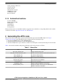
3 Generating the eTPU code
This section describes the procedure to generate and download the etpu code for the PWM example. Go to http://
www.freescale.com/etpu, click eTPU Function Selector and perform the following three steps:
1. Select device PXR40 and choose Pulse Width Modulation.
2. Describe the application. In this case, write "Evaluating the etpu."
3. Click the Compile button, log-in, and choose a folder to save the Zip file to download, then unzip it in a known folder.
Table 1 shows the files included on this package which they will be used to integrate to CW10.x.
Table 1. Library files
File
etpu\_etpu_set\etpu_set.h
etpu\_etpu_set\cpu\ etpu_pwm_auto.h
Description
Image of eTPU functions code
Provides an interface between eTPU code and CPU code
etpu\_utils\etpu_util.c
C code file for utility functions
etpu\_utils\etpu_util.h
Header file for utility functions
etpu\pwm\ etpu_pwm.c
The C code file for the PWM API
etpu\pwm\ etpu_pwm.h
The header file for the PWM API
include\typedefs.h
include\etpu_struc.h
include\mpc5674f_vars.h
Defines all for data types
Register and bit field definitions for the eTPU
Variables that define some features of the MPC5674F.
PXR40 is a derivative of this MCU.
eTPU Libraries Integration to CodeWarrior (CW) 10.x, Rev. 0, 8/2012
Freescale Semiconductor, Inc.
3
Integrating the etpu files to CW10.x
3.1 Function header files
The API includes several header files that contain the function prototypes and define symbolic values for the initialization
and return functions. The following sections describe these header files briefly.
3.1.1 etpu_pwm_auto.h
This header file is automatically generated by the eTPU compiler and defines symbols and their associated values needed to
initialize the PWM function and the offset addresses (in bytes) for each PWM parameter. It is recommended that the content
of this header file should not be modified, because some of the symbol values depend on other functions integrated into the
function set, and these may change depending on the function set used. The standard names of these interfaces files are
etpu_<func>_auto.h, where <func> is the eTPU function abbreviation in lower-case.
3.1.2 etpu_pwm.h
This header file contains the function prototypes of the PWM API C source code contained in etpu_pwm.c. The standard
names of eTPU function API files are etpu_<func>.c/.h, where <func> is the eTPU function abbreviation in lower-case.
3.1.2.1
etpu_util.h
This header file contains the function prototypes to initialize and configure the behavior of the eTPU engine. This header file
also contains symbols used by the eTPU function API. The C source code for configuring and loading the eTPU engine is
contained in etpu_util.c. This header file and the source file are common to use for any etpu API function.
3.1.2.2
etpu_set.h
This file contains the microcode of the eTPU functions that will be loaded into eTPU Code Memory. Only the eTPU
functions from this set will be available for assignment to eTPU channels. The eTPU function set binary images are
distributed as C-header files etpu_setX.h, where X is the function set ID.
Each eTPU function set header file contains:
• the function set binary image
• the global constants
• Entry Table Base (ETB) address
• Multiple Input Signature Calculator (MISC) compare value
For detailed information, see ETPURM : Enhanced Time Processing Unit (eTPU) Reference Manual, available on http://
www.freescale.com.
4 Integrating the etpu files to CW10.x
This section helps the users to create the CW10.x project for the PWM example and integrate the etpu files.
This procedure is specific to PXR40, but the steps may apply to any device that includes an eTPU module.
1. Open the CW10.x.
2. Choose File > New > Bareboard Project to create New Project, and write the project name.
3. Choose PX > PXR Family > PXR4040 to select the device and follow the instructions to create the new project.
eTPU Libraries Integration to CodeWarrior (CW) 10.x, Rev. 0, 8/2012
4
Freescale Semiconductor, Inc.
Building the example code
4. Go to the include folder that was downloaded from the web site http://www.freescale.com/etpu (see Generating the
eTPU code). Select the etpu_struc.h and mpc5674f_vars.h files, and select Copy through right-click. Then go to the
CW project, select Project_Headers, right-click it and select Paste; the typedefs.h file was already included when the
project was created.
5. Select the etpu folder that was downloaded from the web site http://www.freescale.com/etpu (see Generating the eTPU
code), and select Copy through right-click. Then go to the CW project, select Sources, right-click it and select Paste.
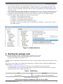
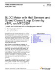
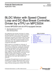
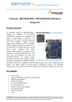
6. Add directories where etpu header files can be found. Choose Project > Properties > C/C++ Build > Settings >
PowerPC Compiler > Input, and add all next locations of the etpu folder:
• "${workspace_loc:/${ProjName}/Sources/etpu}"
• "${workspace_loc:/${ProjName}/Sources/etpu/_utils}"
• "${workspace_loc:/${ProjName}/Sources/etpu/pwm}"
• "${workspace_loc:/${ProjName}/Sources/etpu/_etpu_set/cpu}"
For example, for the first one: Click the 'Add...' icon and then choose Workspace-> <project name> > Sources >
etpu > OK. See Figure 1.
Figure 1. Include directories
5 Building the example code
This section describes the procedure to build the example code. There are two options:
• Reusing the examples code from the eTPU Application notes. See References.
• Using the eTPU Graphical Configuration Tool.
The first option is recommended for eTPU beginner users and the second option helps to build a particular application using
the APIs.
This section uses the example code available from the application note, AN2849: Using the eTPU Pulse Width Modulation
(PWM) Function, on http://www.freescale.com.
• Go to http://www.freescale.com then, on search section, look for AN2849 and on the results, the link
AN2849SW_PWM, appears along with the application note. Click the link and follow the instructions to download,
unzip it and the files for two example codes can be seen.
Table 2. AN2849 files
File
pwm_example1.c
Description
Rev : 2.3 - Example C code file for MPC5500 products.
Table continues on the next page...
eTPU Libraries Integration to CodeWarrior (CW) 10.x, Rev. 0, 8/2012
Freescale Semiconductor, Inc.
5
Building the example code
Table 2. AN2849 files (continued)
File
Description
pwm_example1.h
Rev : 2.2 - Example header file for MPC5500 products.
pwm_example2.c
Rev : 2.3 - More complex example C code file for MPC5500
products.
pwm_example2.h
Rev : 2.2 - More complex example header file for MPC5500
products.
The etpu_pwm.c and etpu_pwm.h files are already included in the etpu/pwm folder that were downloaded from http://
www.freescale.com/etpu. (See Generating the eTPU code)
For the first example in Table 2, copy the pwm_example1.h file and paste it on the Project_Headers folder of the CW10.x
project.
The code for the main.c file of the CW10.x, will be taken from the pwm_example1.c file, so open it, select all the text, copy
and replace it on the main.c file.
The pwm_example1.c file is using the GPIO drivers from the application note, AN2855: Pad Configuration and GPIO Driver
for MPC5500, available on http://www.freescale.com.
• Go to http://www.freescale.com, then, on search section, look for the AN2855 and on the results, the link AN2855SW,
appears. Click this link and follow the instructions to download, unzip it and the files listed in Table 3 will be seen.
Table 3. GPIO files
File
Description
fs_gpio.h
Contains definitions of various macros and functions used by
the fs_gpio API
siu_struct.h
Contains a structure definition for the SIU which is used by
the API.
fs_gpio.c
Contains C code for the fs_gpio API
Copy the fs_gpio.h and siu_struct.h files and paste in the Project_Headers folder of the CW10.x project.
Do the same for the fs_gpio.c file, copy and paste in the Sources folder of the CW10.x project.
Now, on the main.c file, some lines need to be updated to migrate from MPC5554 to PXR4040. See Table 4.
1. Update the headers files.
Table 4. Headers to update for
PXR4040
Header file
Updated header files for PXR4040
#include "..\mpc5500\mpc5554.h"
#include "PXR4040.h"
#include "..\utils\etpu_util.h"
#include "etpu_util.h"
#include "..\mpc5500\fs_gpio.h"
#include "fs_gpio.h"
#include "..\etpu_set1\etpu_set1.h"
#include "_etpu_set\etpu_set.h"
#include "mpc5554_vars.h"
#include "mpc5674f_vars.h"
2. Update the system clock, so delete the line
FMPLL.SYNCR.R = 0x06000000; /* System Frequency set to 128 MHz */
eTPU Libraries Integration to CodeWarrior (CW) 10.x, Rev. 0, 8/2012
6
Freescale Semiconductor, Inc.
Using the eTPU Graphical Configuration Tool
None of the clocks setup for PXR40 will hold the default clock system equal to 60 MHz with 40 MHz Crystal.
3. Change the following line in the eTPU Clock.
const uint32_t etpu_a_tcr1_freq = 64000000;
to
const uint32_t etpu_a_tcr1_freq = 15000000;
2(prescaler) =
15 MHz */
/* 64 MHz */
/* 60 MHz/2=30 MHz(eTPU clock)/
4. Open the pwm_example1.h file and change the header #include "..\utils\etpu_util.h" to #include "etpu_util.h"
5. Finally, open the fs_gpio.h file, locate the definition of FS_GPIO_PRIMARY_FUNCTION and modify the value from
0x0C00 to 0x0400. This step is followed for compatibility with the PX family.
Now the program is ready to compile and run; connect the oscilloscope to ETPU_A Channel 0 and the user can see the PWM
signal running at 2 kHz and 60% of duty.
6 Using the eTPU Graphical Configuration Tool
6.1 Introduction
The eTPU Graphical Configuration Tool (GCT) is a Windows application created for Freescale eTPU users. The GCT offers
a user-friendly graphical environment to configure the eTPU and generate initialization routines coded in C-language.
Main features of the GCT are as follows:
• Graphical environment that guides a user through the configuration: descriptions, options, checking conflicts.
• Supports various Freescale processors with the eTPU. The graphical environment is adjusted to the actual eTPU
features of the selected processor.
• Offers a well-ordered table of channels and assigned eTPU functions.
• No eTPU feature is hidden. All configurable items are available.
• Primarily determined for Freescale provided eTPU function sets, but can be used with any user sets supplied in a proper
format.
• Automatic extraction of configuration information from eTPU function interface routines (API).
• Automatic generation and reading of a C-file containing my_system_etpu_init and my_system_etpu_start functions.
The functions configure the eTPU using standard Freescale eTPU utilities and eTPU functions’ API.
For detailed information, go to Help > User Manual of the eTPU Graphical Configuration Tool, which can be downloaded
from http://www.freescale.com\etpu.
6.2 Creating code to initialize and configure the etpu
This section describes how to use the eTPU GCT to generate code for the initialization and configuration of the eTPU-PWM
example.
1. Create a new project and repeat the steps given in Integrating the etpu files to CW10.x.
2. Choose Start > All programs > Freescale > eTPU Graphical Configuration Tool > eTPU Graphical Configuration Tool,
to open the eTPU GCT.
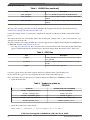
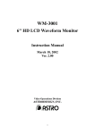
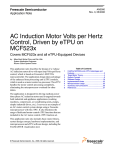
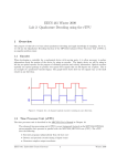
3. Choose eTPU > Options > Function Sets > <Path of the etpu libraries folder> > OK, to set the path where eTPU
libraries were downloaded, according to Generating the eTPU code. See Figure 2.
eTPU Libraries Integration to CodeWarrior (CW) 10.x, Rev. 0, 8/2012
Freescale Semiconductor, Inc.
7
Using the eTPU Graphical Configuration Tool
Figure 2. Setting the path to eTPU Files
4. Close the eTPU Graphical Configuration Tool without saving and open it again; this will update the link that will point
to the path setting on step 3.
5. Click the Processor tab and choose MPC5674F to select the target CPU. Click Processor tab and choose System clock
> 128 MHz to set the Clock Settings to 128 MHz.
6. Click the Function Set tab and choose etpu_set.h to select the eTPU Function Set to be used.
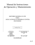
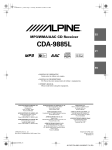
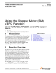
7. Configure the Engine A, as depicted in Figure 3.
• Select Engine A tab.
• Choose TCR1 > Clock Source, and select Internal: eTPU clock divided by 2.
• Set all other configuration by default.
eTPU Libraries Integration to CodeWarrior (CW) 10.x, Rev. 0, 8/2012
8
Freescale Semiconductor, Inc.
Using the eTPU Graphical Configuration Tool
Figure 3. Configuring the Engine A
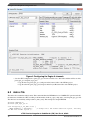
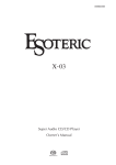
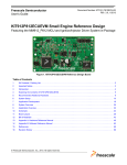
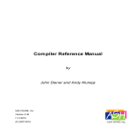
8. Configure the Engine A Channels, as shown in Figure 4.
• Click the Add Function button, and the Add eTPU Function windows dialog box appears.
• Go to Parameter Values section and change the priority value to Middle.
• Set the freq value to 2000 kHz and set the duty value to 5000; it represents 50%. (Resolution = 0.01%)
• Set all other values by default.
eTPU Libraries Integration to CodeWarrior (CW) 10.x, Rev. 0, 8/2012
Freescale Semiconductor, Inc.
9
Using the eTPU Graphical Configuration Tool
Figure 4. Configuring the Engine A channels
• Save the eTPU configuration as pwm_etpu_gct.c in a known folder. Go to this folder and there will be two files,
pwm_etpu_gct.c and pwm_etpu_gct.h.
• Copy the first one (pwm_etpu_gct.c ) and paste in the Sources folder of the CW10.x project.
• Copy the other file (pwm_etpu_gct.h) and paste in the Project Headers folder of the CW10.x project.
6.3 main.c file
The main.c file contains the main() routine. This routine initializes the PXR40 device for 256 MHz CPU operation and calls
the functions to initialize the eTPU according to the information in the my_etpu_config struct, stored in pwm_etpu_gct.c file.
The time bases are enabled by calling routine fs_timer_start(). This example uses the pin ETPUA0.
#include "PXR4040.h"
#include "pwm_etpu_gct.h"
void initSysclk_at_256_MHz (void) {
FMPLL.ESYNCR2.R = 0x00000003;
/* Change clk to PLL normal mode from crystal, initially
128 MHz with 40 MHz crystal */
eTPU Libraries Integration to CodeWarrior (CW) 10.x, Rev. 0, 8/2012
10
Freescale Semiconductor, Inc.
Summary
FMPLL.ESYNCR1.R = 0xF0040030;/* EPREDIV = 4; EMFD = 48; CLKCFG = 7 */
while (FMPLL.SYNSR.B.LOCK != 1) {};/* Wait for FMPLL to LOCK */
FMPLL.ESYNCR2.R = 0x00000001; /* Change divider final value for 256 MHz sysclk */
}
int main(void) {
volatile int i = 0;
initSysclk_at_256_MHz();
SIU.PCR[114].R = 0x0600;
my_system_etpu_init ();
my_system_etpu_start();
}
/* Init system clock at 256 MHz*/
/* Enable ETPU_A Channel 0 as output */
/* Init the eTPU engine and eTPU channels
/* Start eTPU (and eMIOS) timers */
*/
/* Loop forever */
for (;;) {
i++;
}
Compile and run the project, connect the oscilloscope to ETPU_A Channel 0 and the user will see the PWM signal running at
2 kHz and 50% of duty.
7 Summary
A set of eTPU functions configured to cooperate together is called eTPU application. An eTPU application API capsulizes
several eTPU function APIs. The eTPU application API includes CPU methods which show how to initialize, control, and
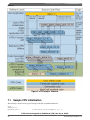
monitor an eTPU application, and to easily use the eTPU as a coprocessor. Figure 5 shows an example of the eTPU project
structure for motor control.
eTPU Libraries Integration to CodeWarrior (CW) 10.x, Rev. 0, 8/2012
Freescale Semiconductor, Inc.
11
Summary
Figure 5. eTPU project structure
7.1 Sample CPU initialization
The following code lines show a typical example of the CPU and eTPU initialization.
main()
PXR40_init(…)
mySystem_init(…);
/* Initialize sysclk frequency, etc. */
eTPU Libraries Integration to CodeWarrior (CW) 10.x, Rev. 0, 8/2012
12
Freescale Semiconductor, Inc.
Conclusion
fs_etpu_init(…)/* Configure the eTPU engine, copy code and globals */
fs_etpu_api1_init(…); /* Assign one channel to run a function */
fs_etpu_api2_init(…);
/* Assign one channel to run a function */
configure_SIU_pads();/* Assign pads for eTPU */
fs_timer_start(…);
/* Start eTPU (and eMIOS) timers */
8 Conclusion
This application note describes how to integrate the eTPU libraries into a stationary-based CW10.x project to use the eTPU
function. It also describes how to use the eTPU GCT and illustrates its use with working PWM examples. The simple C
interface routines of the eTPU PWM function enable easy implementation of the PWM function in applications. The routines
are aimed at the PXR40 family of devices, but they can be used with any device that has an eTPU.
The benefit of the eTPU host interface design is to isolate any hardware dependency from the application software by means
of the host interface API functions. In the eTPU host interface design, all the interactions between host and eTPU are
encapsulated in the interface API functions. With this interface design, the implementation of the low-level driver can be
hidden from the host application.
9 References
Numerous examples of documents are available in the general set and APIs available on http://www.freescale.com. The
following subsections categorically list these documents.
9.1 General documentation and utilities
Item
Description
Software
ETPURM
Enhanced Time Processing Unit (eTPU)
Reference Manual
-
ETPURMAD
eTPU Reference Manual Addendum
-
AN2353
The Essentials of Enhanced Time
Processing Unit
-
AN2821
eTPU Host Interface
-
AN2848
Programming the eTPU
-
AN2864
General C Functions for the eTPU
AN2864SW
AN2897
Using the eTPU Angle Clock
-
AN2933
Understanding the eTPU Channel
Hardware
-
eTPU Libraries Integration to CodeWarrior (CW) 10.x, Rev. 0, 8/2012
Freescale Semiconductor, Inc.
13
References
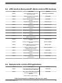
9.2 eTPU function library and API –General timing eTPU
functions
Item
Description
Software
AN2863
eTPU General Function Set (Set 1)
AN2863SW_GENERALSET
AN2849
Using the eTPU Pulse Width Modulation
(PWM) Function
AN2849SW_PWM
AN2850
Using the General Purpose Input/Output
(GPIO) eTPU Function
AN2850SW_GPIO
AN2851
Using the Input Capture (IC) eTPU
Function
AN2851SW_IC_21
AN2852
Using the Output Compare (OC) eTPU
Function
AN2852SW_OC
AN2854
Using the Synchronized Pulse-Width
Modulation eTPU Function
AN2854SW
AN2857
Using the Queued Output Match (QOM)
eTPU Function
AN2857SW_QOM
AN2858
Using the Period and Pulse Accumulator
(PPA) eTPU Function
AN2858SW
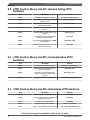
9.3 eTPU function library and API –Communication eTPU
functions
Item
Description
Software
AN2863
eTPU General Function Set (Set 1)
AN2863SW_GENERALSET
AN2847
Using the Serial Peripheral Interface
(SPI) eTPU Function
AN2847SW_SPI
AN2853
Using the Universal Asynchronous
Receiver Transmitter (UART) eTPU
Function
AN2853SW_UART
AN3379
Using the CEA709 eTPU Function
AN3379SW_CEA709_SET
9.4 eTPU function library and API –Automotive eTPU functions
Item
Description
Software
AN3768
eTPU Automotive Function Set (Set 2)
AN3768SW
AN3769
Using the Engine Position (CRANK and
CAM) eTPU Functions
AN3769SW
AN3770
Using the Fuel eTPU Function
AN3770SW
AN3771
Using the Spark eTPU Function
AN3771SW_SPARK
AN3772
Using the Knock Window eTPU Function
AN3772SW_KNOCKWINDOW
eTPU Libraries Integration to CodeWarrior (CW) 10.x, Rev. 0, 8/2012
14
Freescale Semiconductor, Inc.
References
9.5 eTPU function library and API –Motor control eTPU functions
Item
Description
Software
AN2958
Using the DC Motor Control eTPU
Function Set (set3)
AN2958SW_DCMOTORSET
AN2968
Using the AC Motor Control eTPU
Function Set (set4)
AN2968SW
AN2840
Using the DC Motor Control PWM eTPU
Functions
AN2840SW
AN2841
Using the Hall Decoder (HD) eTPU
Function
AN2841SW_HD
AN2842
Using the Quadrature Decoder (QD)
eTPU Function
AN2842SW_QD
AN2843
Using the Speed Controller (SC) eTPU
Function
AN2843SW_SC
AN2844
Using the Current Controller (CC) eTPU
Function
AN2844SW_CC
AN2845
Using the Break Controller (BC) eTPU
Function
AN2845SW_BC
AN2846
Using the Analog Sensing for DC Motors
(ASDC) eTPU Function
AN2846_ASDC
AN2869
Using the Stepper Motor (SM) eTPU
Function
AN2869SW_SM
AN2969
Using the AC Motor Control PWM eTPU
Functions
AN2969_PWMMAC
AN2970
Using the Analog Sensing for AC Motors
(ASAC) eTPU Function
AN2970_ASAC
AN2971
Using the ACIM Volts per Hertz
(ACIMVHZ) eTPU Function
AN2971_ACIMVHZ
AN2972
Using the PMSM Vector Control eTPU
Function
AN2972SW
AN2973
Using the ACIM Vector Control eTPU
Function
AN2973_ACIMVC
AN3943
Using the ACIM Resolver Interface
eTPU Function
AN3943SW
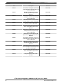
9.6 Example motor control eTPU applications
Item
Description
Software
AN2892
3-Phase BLDC Motor with Speed Closed
Loop, driven by eTPU on MCF523x
AN2892SW
AN2948
Three 3-Phase BLDC Motors with Speed
Closed Loop, driven by eTPU on
MCF523x
AN2948SW
Table continues on the next page...
eTPU Libraries Integration to CodeWarrior (CW) 10.x, Rev. 0, 8/2012
Freescale Semiconductor, Inc.
15
References
Item
Description
Software
AN2954
BLDC Motor with Speed Closed Loop
and DC-Bus Break Controller, driven by
eTPU on MCF523x
AN2954SW
AN2955
DC Motor with Speed and Current
Closed Loops, driven by eTPU on
MCF523x
AN2955SW
AN2957
BLDC Motor with Quadrature Encoder
and Speed Closed Loop, Driven by
eTPU on MCF523x
AN2957SW
AN3000
AC Induction Motor Volts per Hertz
Control, Driven by eTPU on MCF523x
AN3000SW
AN3001
AC Induction Motor Vector Control,
Driven by eTPU on MPC5500
AN3001SW
AN3002
Permanent Magnet Synchronous Motor
Vector Control, Driven by eTPU on
MCF523x
AN3002SW
AN3005
BLDC Motor with Quadrature Encoder
and Speed Closed Loop, driven by
eTPU on MPC5554
AN3005SW
AN3006
BLDC Motor with Hall Sensors and
Speed Closed Loop, driven by eTPU on
MPC5554
AN3006SW
AN3007
BLDC Motor with Speed Closed Loop
and DC-Bus Break Controller, driven by
eTPU on MPC5554
AN3007SW
AN3008
DC Motor with Speed and Current
Closed Loops, Driven by eTPU on
MPC5554
AN3008SW
AN3205
AC Induction Motor Volts per Hertz
Control with Speed Closed Loop, Driven
by eTPU on MPC5500
AN3205SW
AN3206
Permanent Magnet Synchronous Motor
Vector Control, Driven by eTPU on
MPC5500
AN3206SW
AN3769
Using the Engine Position eTPU
Functions
AN3769SW
eTPU Libraries Integration to CodeWarrior (CW) 10.x, Rev. 0, 8/2012
16
Freescale Semiconductor, Inc.
How to Reach Us:
Home Page:
www.freescale.com
Web Support:
http://www.freescale.com/support
USA/Europe or Locations Not Listed:
Freescale Semiconductor
Technical Information Center, EL516
2100 East Elliot Road
Tempe, Arizona 85284
+1-800-521-6274 or +1-480-768-2130
www.freescale.com/support
Europe, Middle East, and Africa:
Freescale Halbleiter Deutschland GmbH
Technical Information Center
Schatzbogen 7
81829 Muenchen, Germany
+44 1296 380 456 (English)
+46 8 52200080 (English)
+49 89 92103 559 (German)
+33 1 69 35 48 48 (French)
www.freescale.com/support
Japan:
Freescale Semiconductor Japan Ltd.
Headquarters
ARCO Tower 15F
1-8-1, Shimo-Meguro, Meguro-ku,
Tokyo 153-0064
Japan
0120 191014 or +81 3 5437 9125
[email protected]
Asia/Pacific:
Freescale Semiconductor China Ltd.
Exchange Building 23F
No. 118 Jianguo Road
Chaoyang District
Beijing 100022
China
+86 10 5879 8000
[email protected]
Document Number: AN4572
Rev. 0, 8/2012
Information in this document is provided solely to enable system and software
implementers to use Freescale Semiconductors products. There are no express or implied
copyright licenses granted hereunder to design or fabricate any integrated circuits or
integrated circuits based on the information in this document.
Freescale Semiconductor reserves the right to make changes without further notice to any
products herein. Freescale Semiconductor makes no warranty, representation, or
guarantee regarding the suitability of its products for any particular purpose, nor does
Freescale Semiconductor assume any liability arising out of the application or use of any
product or circuit, and specifically disclaims any liability, including without limitation
consequential or incidental damages. "Typical" parameters that may be provided in
Freescale Semiconductor data sheets and/or specifications can and do vary in different
applications and actual performance may vary over time. All operating parameters,
including "Typicals", must be validated for each customer application by customer's
technical experts. Freescale Semiconductor does not convey any license under its patent
rights nor the rights of others. Freescale Semiconductor products are not designed,
intended, or authorized for use as components in systems intended for surgical implant
into the body, or other applications intended to support or sustain life, or for any other
application in which failure of the Freescale Semiconductor product could create a
situation where personal injury or death may occur. Should Buyer purchase or use
Freescale Semiconductor products for any such unintended or unauthorized application,
Buyer shall indemnify Freescale Semiconductor and its officers, employees, subsidiaries,
affiliates, and distributors harmless against all claims, costs, damages, and expenses, and
reasonable attorney fees arising out of, directly or indirectly, any claim of personal injury
or death associated with such unintended or unauthorized use, even if such claims alleges
that Freescale Semiconductor was negligent regarding the design or manufacture of
the part.
RoHS-compliant and/or Pb-free versions of Freescale products have the functionality and
electrical characteristics as their non-RoHS-complaint and/or non-Pb-free counterparts.
For further information, see http://www.freescale.com or contact your Freescale
sales representative.
For information on Freescale's Environmental Products program, go to
http://www.freescale.com/epp.
Freescale™ and the Freescale logo are trademarks of Freescale Semiconductor, Inc.
All other product or service names are the property of their respective owners.
© 2012 Freescale Semiconductor, Inc.