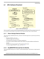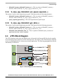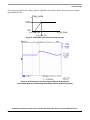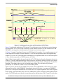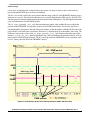
1
Freescale Semiconductor
Application Note
AN3007
Rev. 0, 08/2005
BLDC Motor with Speed Closed
Loop and DC-Bus Break Controller,
Driven by eTPU on MPC5554
Covers MPC5554 and all eTPU-equipped Devices
by: Milan Brejl & Michal Princ & Pavel Sustek
System Application Engineers
Roznov Czech System Center
This application note describes the design of a 3-phase
brushless DC (BLDC) motor drive based on Freescale’s
PowerPC MPC5554 microcontroller. The application
design takes advantage of the enhanced time processing
unit (eTPU) module, which is used as a motor control
co-processor. The eTPU completely handles the motor
control processing, eliminating the microprocessor
overhead for other duties.
BLDC motors are very popular in a wide array of
applications. Compared to a DC motor, the BLDC motor
uses an electric commutator, replacing the mechanical
commutator and making it more reliable than the DC
motor. In BLDC motors, rotor magnets generate the
rotor’s magnetic flux, allowing BLDC motors to achieve
higher efficiency. Therefore, BLDC motors may be used
in high-end white goods (refrigerators, washing
machines, dishwashers, etc.), high-end pumps, fans, and
other appliances that require high reliability and
efficiency.
The concept of the application is to create a speed-closed
loop BLDC driver using a Hall position sensor. It serves
as an example of a BLDC motor control system design
using a Freescale microprocessor with the eTPU. It also
© Freescale Semiconductor, Inc., 2005. All rights reserved.
Table of Contents
1
2
3
4
5
6
7
8
PowerPC MPC5554 and eTPU Advantages and
Features ..............................................................2
Target Motor Theory ............................................4
System Concept ..................................................8
Software Design ................................................18
Implementation Notes .......................................43
Microprocessor Usage ......................................47
Summary and Conclusions ...............................48
References ........................................................48
PowerPC MPC5554 and eTPU Advantages and Features
illustrates the usage of dedicated motor control eTPU functions that are included in the DC motor control
eTPU function set.
This application note also includes basic motor theory, system design concept, hardware implementation,
and microprocessor and eTPU software design, including the FreeMASTER visualization tool.
Figure 1. Using MPC5554DEMO, 33395 Evaluation Motor Board, and Pittman BLDC Motor
1
PowerPC MPC5554 and eTPU Advantages and
Features
1.1
PowerPC MPC5554 Microcontroller
The MPC5554 microcontroller is a family of next generation powertrain microcontrollers based on the
PowerPC Book E architecture. Featuring two 32 channels eTPU engines, 32 Kbytes of cache, 64 Kbytes
of internal SRAM, 2 Mbytes of internal Flash memory, a 64-channel eDMA controller, 3 FlexCAN
modules, 3 UARTs and four DSPI modules, the MPC5554 family has been designed for applications that
require complex, real-time control.
BLDC Motor with Speed Closed Loop and DC-Bus Break Controller, Driven by eTPU on MPC5554, Rev. 0
2
Freescale Semiconductor
PowerPC MPC5554 and eTPU Advantages and Features
This 32-bit device is based on the PowerPC operating at a core frequency up to 132 MHz. On-chip modules
include the following:
• High-performance 32-bit PowerPC Book E-compliant core
• Memory management unit (MMU) with 24-entry fully associative translation look-aside buffer
(TLB)
• 2MB of embedded Flash memory with error correction coding (ECC)
• 64 KB on-chip L2 static RAM with ECC
• 32 KB of cache that can be configured as additional RAM
• nexus IEEE-ISTO 5001 class multicore debug capabilities
• Two enhanced time processor units (eTPUs)
• 64-channel enhanced direct memory access (eDMA) controller
• Interrupt controller (INTC) capable of handling 286 satiable-priority interrupt sources
• Frequency modulated phase-locked loop (FMPLL) to assist in electromagnetic interference (EMI)
management
• Enhanced queued analog-to-digital converter (eQADC)
• Four deserial serial peripheral interface (DSPI) modules
• Three controller area network (FlexCAN) modules
• Two enhanced serial communication interface (eSCI) modules
• Eighty-eight channels of timed I/O
• Crossbar switch (XBAR)
• Enhanced modular I/O system (eMIOS)
For more information, refer to Reference 1.
1.2
eTPU Module
The eTPU is an intelligent, semi-autonomous co-processor designed for timing control, I/O handling,
serial communications, motor control, and engine control applications. It operates in parallel with the host
CPU. The eTPU processes instructions and real-time input events, performs output waveform generation,
and accesses shared data without the host CPU’s intervention. Consequently, the host CPU setup and
service times for each timer event are minimized or eliminated.
The eTPU on the MCP5554 microcontroller has two engines with up to 32 timer channels for each. In
addition, it has 16 Kbytes of code memory and 3 Kbytes of data memory that stores software modules
downloaded at boot time and that can be mixed and matched as required for any specific application.
The eTPU provides more specialized timer processing than the host CPU can achieve. This is partially due
to the eTPU implementation, which includes specific instructions for handling and processing time events.
In addition, channel conditions are available for use by the eTPU processor, thus eliminating many
branches. The eTPU creates no host CPU overhead for servicing timing events.
For more information, refer to Reference 8.
BLDC Motor with Speed Closed Loop and DC-Bus Break Controller, Driven by eTPU on MPC5554, Rev. 0
Freescale Semiconductor
3
Target Motor Theory
2
Target Motor Theory
A brushless DC (BLDC) motor is a rotating electric machine where the stator is a classic three-phase stator,
like that of an induction motor, and the rotor has surface-mounted permanent magnets (see Figure 2).
Stator
Stator winding
(in slots)
Shaft
Rotor
Air gap
Permanent magnets
Figure 2. BLDC Motor - Cross Section
In this respect, the BLDC motor is equivalent to a reversed DC commutator motor, in which the magnet
rotates while the conductors remain stationary. In the DC commutator motor, the current polarity is altered
by the commutator and brushes. Unlike the brushless DC motor, the polarity reversal is performed by
power transistors switching in synchronization with the rotor position. Therefore, BLDC motors often
incorporate either internal or external position sensors to sense the actual rotor position, or the position can
be detected without sensors.
2.1
Digital Control of a BLDC Motor
The BLDC motor is driven by rectangular voltage strokes coupled with the given rotor position (see
Figure 3). The generated stator flux interacts with the rotor flux, which is generated by a rotor magnet and
defines the torque and thus the speed of the motor. The voltage strokes must be properly applied to two
phases of the three-phase winding system so that the angle between the stator flux and the rotor flux is kept
as close to 90° as possible, to get the maximum generated torque. Therefore, the motor requires electronic
control for proper operation.
BLDC Motor with Speed Closed Loop and DC-Bus Break Controller, Driven by eTPU on MPC5554, Rev. 0
4
Freescale Semiconductor
Target Motor Theory
Voltage
+UDCB
Phase A
-UDCB
+UDCB
Phase B
-UDCB
+UDCB
Phase C
-UDCB
30º
60º
90º
120º
150º
180º
210º
240º
270º
300º
330º Electrical
angle
Figure 3. Voltage Strokes Applied to the 3-Phase BLDC Motor
For the common 3-phase BLDC motor, a standard 3-phase power stage is used (see Figure 4). The power
stage utilizes six power transistors that operate in either an independent or complementary mode.
In both modes, the 3-phase power stage energizes two motor phases concurrently. The third phase is
unpowered (see Figure 3). Thus, we get six possible voltage vectors that are applied to the BLDC motor
using a pulse width modulation (PWM) technique (see Figure 5). There are two basic types of power
transistor switching schemes: independent and complementary. Both switching modes are able to work in
bipolar or unipolar mode. The presented application utilizes the complementary bipolar PWM mode.
For more information about PWM techniques, refer to Reference 16.
U DCB
PWM_Q3
PWM_Q1
Q5
Q3
Q1
PWM_Q5
C1
Q2
PWM_Q2
Q4
PWM_Q4
Q6
PWM_Q6
GND
Phase_A
Phase_B
Phase_C
Figure 4. 3-Phase BLDC Power Stage
BLDC Motor with Speed Closed Loop and DC-Bus Break Controller, Driven by eTPU on MPC5554, Rev. 0
Freescale Semiconductor
5
Target Motor Theory
2.1.1
Commutation
Commutation provides the creation of a rotational field. As mentioned earlier, for proper operation of a
BLDC motor, it is necessary to keep the angle between the stator and rotor flux as close to 90° as possible.
We get a total of six possible stator flux vectors with a six-step control. The stator flux vector must be
changed at specific rotor positions, which are usually sensed by the Hall sensors. The Hall sensors generate
three signals that also consist of six states. Each of the Hall sensors’ states correspond to a certain stator
flux vector. All of the Hall sensors states, with corresponding stator flux vectors, are illustrated in Figure 5.
Figure 5. Stator Flux Vectors at Six-Step Control
The next two figures depict the commutation process. The actual rotor position in Figure 6 corresponds to
the Hall sensors state ABC[110] (see Figure 5). Phase A is connected to the positive DC bus voltage by
the transistor Q1, phase C is connected to the ground by transistor Q6, and phase B is unpowered.
As soon as the rotor reaches a certain position (see Figure 7), the Hall sensors state changes its value from
ABC[110] to ABC[100]. A new voltage pattern is selected and applied to the BLDC motor.
As shown below, when using the six-step control technique, it is difficult to keep the angle between the
rotor flux and the stator flux precisely at 90° in a six-step control technique. The actual angle varies from
60° to 120°.
The commutation process is repeated per each 60 electrical degrees and is critical to maintain its angular
(time) accuracy. Any deviation causes torque ripples, resulting in speed variation.
BLDC Motor with Speed Closed Loop and DC-Bus Break Controller, Driven by eTPU on MPC5554, Rev. 0
6
Freescale Semiconductor
Target Motor Theory
Figure 6. Situation Right Before Commutation (Counter-clockwise Motion)
Figure 7. Situation Right After Commutation
2.1.2
Speed Control
Commutation ensures the proper rotor rotation of the BLDC motor, while the motor speed only depends
on the amplitude of the applied voltage. The amplitude of the applied voltage is adjusted using the PWM
technique. The required speed is controlled by a speed controller, which is implemented as a conventional
proportional-integral (PI) controller. The difference between the actual and required speeds is input to the
PI controller which then, based on this difference, controls the duty cycle of the PWM pulses which
correspond to the voltage amplitude required to maintain the desired speed.
BLDC Motor with Speed Closed Loop and DC-Bus Break Controller, Driven by eTPU on MPC5554, Rev. 0
Freescale Semiconductor
7
System Concept
Power Stage
ωdesired
Σ
-
ωerror
Speed
Controller
PWM Output
Duty Cycle
ωactual
PWM
Generator
Commutation
Hall Sensors
Figure 8. Speed Controller
The speed controller calculates the PI algorithm given in the equation below:
1 t
u ( t ) = K c e ( t ) + ----- ∫ e ( τ ) dτ
TI 0
After transforming the equation into a discrete time domain using an integral approximation with the
Backward Euler method, we get the following equations for the numerical PI controller calculation:
u ( k ) = uP ( k ) + uI ( k )
uP ( k ) = Kc ⋅ e ( k )
T
u I ( k ) = u I ( k – 1 ) + K c ----- ⋅ e ( k )
TI
where:
e(k)
w(k)
m(k)
u(k)
up(k)
uI(k)
uI(k-1)
TI
T
Kc
=
=
=
=
=
=
=
=
=
=
Input error in step k
Desired value in step k
Measured value in step k
Controller output in step k
Proportional output portion in step k
Integral output portion in step k
Integral output portion in step k-1
Integral time constant
Sampling time
Controller gain
3
System Concept
3.1
System Outline
The system is designed to drive a 3-phase BLDC motor. The application meets the following performance
specifications:
• Voltage control of a BLDC motor using Hall sensors
• Targeted at PowerPC MPC5554DEMO evaluation board (MPC554DEMO), interface board with
UNI-3, 33395 evaluation motor board, and Pittman BLDC motor (N2311)
BLDC Motor with Speed Closed Loop and DC-Bus Break Controller, Driven by eTPU on MPC5554, Rev. 0
8
Freescale Semiconductor
System Concept
•
•
•
•
•
3.2
Control technique incorporates:
— Voltage BLDC motor control with speed-closed loop
— Both directions of rotation
— 4-quadrant operation
— Start from any motor position without rotor alignment
— Minimum speed of 300 RPM
— Maximum speed of 10000 RPM (limited by power supply)
Manual interface (start/stop switch, up/down push button control, LED indication)
FreeMASTER control interface (speed set-up, speed loop close/open choice)
FreeMASTER monitor
— FreeMASTER graphical control page (required speed, actual motor speed, start/stop status,
fault status)
— FreeMASTER speed control scope (observes required, ramp, and actual speeds, applied
voltage)
— Detail description of all eTPU functions used in the application (monitoring of channel
registers and all function parameters in real time)
DC bus over-current fault protection
Application Description
A standard system concept is chosen for the motor control function (see Figure 9). The system
incorporates the following hardware:
• Evaluation board MPC5554DEMO
• Interface board with UNI-3
• 33395 evaluation motor board
• Pittman BLDC motor N2311 with Hall sensors
• Power supply 12V DC, 2.7 Amps
The eTPU module runs the main control algorithm. The 3-phase PWM output signals for a 3-phase inverter
are generated according to feedback signals from Hall sensors and the input variable values, provided by
the microprocessor CPU.
BLDC Motor with Speed Closed Loop and DC-Bus Break Controller, Driven by eTPU on MPC5554, Rev. 0
Freescale Semiconductor
9
System Concept
Status LED
Hardware
Fault LED
9÷12V DC
CPU
Over-current
interrupt
Fault
Signal
EMIOS
eTPU
ON/OFF
switch
status
DOWN
FreeMaster
Remote Control
RS232
UART
UP
GPIO
ON/OFF
DC-bus break
control
Application
State Machine
enable/disable
PWM signals
BLDC
Motors
Drive
PWM
3-Phase
Power Stage
Signals
required speed
data monitoring
Hall Sensor
Signals
BLDC
motor
Figure 9. System Concept
The system processing is distributed between the CPU and the eTPU, which both run in parallel.
The CPU performs the following tasks:
• Periodically scans the user interface (ON/OFF switch, up and down buttons, FreeMASTER).
Based on the user input, it handles the application state machine and calculates the required
speeds, which is passed to the eTPU.
• Periodically reads application data from eTPU DATA RAM in order to monitor application
variables.
• In the event of an overcurrent fault, the PWM outputs are immediately temporarily disabled by
the eTPU hardware. Then, after an interrupt latency, the CPU disables the PWM outputs
permanently and displays the fault state.
The eTPU performs the following tasks:
• Six eTPU channels (PWMC) are used to generate PWM output signals.
• Three eTPU channels (HD) are used to process Hall sensor signals. On each incoming edge, a
revolution period is calculated and the PWM output signals are commuted.
• One eTPU channel (BC) is used for controlling the DC-bus break.
• eTPU controls a speed closed loop. The actual motor speed is calculated based on the revolution
period and compared with the required speed, provided by the CPU and passed through a ramp.
The speed PI control algorithm processes the error between the required and actual speed. The PI
controller output is passed to the PWM generator as a newly corrected value of the applied motor
voltage.
BLDC Motor with Speed Closed Loop and DC-Bus Break Controller, Driven by eTPU on MPC5554, Rev. 0
10
Freescale Semiconductor
System Concept
Figure 10. The Application and FreeMASTER Screen
3.2.1
User Interface
The application is interfaced by the following:
• ON/OFF switch on the interface board with UNI-3
• Up/down buttons on the interface board with UNI-3, or
FreeMASTER running on a PC connected to the MPC5554DEMO via an RS232 serial cable.
The ON/OFF switch affects the application state and enables and disables the PWM phases. When the
switch is in the off-position, no voltage is applied to the motor windings. When the ON/OFF switch is in
BLDC Motor with Speed Closed Loop and DC-Bus Break Controller, Driven by eTPU on MPC5554, Rev. 0
Freescale Semiconductor
11
System Concept
the on-position, the motor speed can be controlled either by the up and down buttons on the interface
board, or by the FreeMASTER on the PC. The FreeMASTER also displays a control page, real-time values
of application variables, and their time behavior using scopes.
FreeMASTER software was designed to provide an application-debugging, diagnostic, and demonstration
tool for the development of algorithms and applications. It runs on a PC connected to the MPC5554DEMO
via an RS232 serial cable. A small program resident in the microprocessor communicates with the
FreeMASTER software to return status information to the PC and process control information from the
PC. FreeMASTER software, executing on a PC, uses part of Microsoft Internet Explorer as the user
interface.
Note, that FreeMASTER version 1.2.31.1 or higher is required. The FreeMASTER application can be
downloaded from http://www.freescale.com. For more information about FreeMASTER, refer to
Reference 7.
3.3
Hardware Implementation and Application Setup
As previously stated, the application runs on the MPC5554 family of PowerPC microprocessors using the
following:
• MPC5554DEMO
• Interface board with UNI-3
• 33395 evaluation motor board
• Pittman N2311 3-phase BLDC motor
• Power supply, 12V DC, minimum 2.7 Amps
Figure 11 shows the connection of these parts. All system parts are supplied by Freescale and documented
according to references.
3.3.1
PowerPC MPC5554 Evaluation Board (MPC5554DEMO)
This board is not intended to be a full evaluation board for the MPC5554, but shows a minimal system for
learning about the new MPC5500 family of product.
The FLASH memory placed on the MPC5554 has three address spaces. Low and mid address spaces are
256-Kbytes, and high address spaces are 1.5 Mbyte in size. This gives a total memory space of 2Mbytes.
For more information, refer to Reference 2.
Table 1 lists all MPC5554DEMO jumper settings used in the application.
BLDC Motor with Speed Closed Loop and DC-Bus Break Controller, Driven by eTPU on MPC5554, Rev. 0
12
Freescale Semiconductor
System Concept
Figure 11. Connection of Application Parts
Table 1. . MPC5554DEMO Jumper Settings.
3.3.2
Jumper
Setting
CAN_SEL
Setting
CONFIG SWITCH
Setting
JP1 - 1
JP1 - 2
JP2
JP3
JP4
JP5
VRH_EN
SRAM_SEL
VSTBY_SWITCH
1-2
1-2
1- 2 3
1-2
1-2 3
1-2
1-2
1-2 3
ON
1
2
3
4
5
6
12
12
12
12
12
12
1
2
3
4
5
6
ON
OFF
ON
OFF
ON
OFF
Flashing the MPC5554DEMO
The eSys Flasher utility can be used for programming code into the FLASH memory on the
MPC5554DEMO. Check for correct setting of switches and jumpers. The flashing procedure is as follows:
1. Run Metrowerks MPC55xx V1.5b2 and open the project. Choose the Intflash target and compile
the application. A file simple_eflash.elf.S19, which will be loaded into FLASH memory, is created
in the project directory bin.
BLDC Motor with Speed Closed Loop and DC-Bus Break Controller, Driven by eTPU on MPC5554, Rev. 0
Freescale Semiconductor
13
System Concept
2. Run the eSysFlasher application. In the Target Configuration window select the type of the BDM
Communication as P&E Wiggler. Click OK to close the window.
3. Go to the Program section by clicking the “Program Flash” button (see Figure 12). Select the
Binary Image, set Address as 0x0 and check the “Verify after program” option (see Figure 13).
Press the “Program” and select intflash.bin file. Finally, press “Open” button at the bottom of the
window to start loading the code into the FLASH memory.
Figure 12. eSysFlasher Target Configuration Window
4. If the code has been programmed correctly, remove the BDM interface and push the RESET
button on the MPC5554Demo. The application should now run from the FLASH.
The eSYS Flasher application can be downloaded from http://www.freescale.com.
BLDC Motor with Speed Closed Loop and DC-Bus Break Controller, Driven by eTPU on MPC5554, Rev. 0
14
Freescale Semiconductor
System Concept
Figure 13. eSys Flasher Program Window
3.3.3
Interface Board with UNI-3
This board enables to connect the power stage with a motor to the MPC5554DEMO board and can be used
by software and hardware developers to test programs and tools. It supports algorithms that use Hall
sensors, LEM sensors, encoder feedback and back-EMF (electromotive force) signals for sensors control.
Input connections are made via connectors on the bottom side of the board and headers on
theMPC5554DEMO board. Output connections are made via 40-pin UNI-3 connector and expansion
headers. Power requirements are met by input connectors.
Figure 14. Interface Board with UNI-3
For more information, refer to Reference 5
BLDC Motor with Speed Closed Loop and DC-Bus Break Controller, Driven by eTPU on MPC5554, Rev. 0
Freescale Semiconductor
15
System Concept
3.3.4
Setting Overcurrent Level
The over-current fault signal is connected to the eMIOS output disable input pin (eMIOS 10) that enables,
together with a proper eTPU configuration, handling the fault by eTPU hardware. This connection is part
of the MPC5554. In order to enable handling the fault also by a software, the fault signal, available on
eMIOS 10 pin generates interrupt request to the CPU in case of a fault.
The over-current level is set by the trimmer R24 (I_SEN) on the interface board with UNI-3 (see
Figure 15). Reference 5 describes what voltage must the trimmer define for the over-current comparator.
Perform the following steps in order to set up the over-current level properly without measuring the
voltage:
1. Connect all system parts according to Figure 11.
2. Download and start the application.
3. Turn ON/OFF switch ON. Using up and down buttons set the required speed to the maximum.
4. Adjust the R24 trimmer. You can find a level from which the red LED starts to light and the motor
speed starts to be limited. Set the trimmer level somewhat higher, so that the motor can run at the
maximum speed.
5. Turn the ON/OFF switch OFF.
6. Turn ON/OFF switch ON. Using up and down buttons set the required speed to the maximum.
7. If the application goes to the fault state during the acceleration, adjust the R24 trimmer level
somewhat higher, so that the motor can get to the maximum speed.
the
Figure 15. Overcurrent Level Trimmer on Interface Board with UNI-3 (R24)
3.3.5
33395 Evaluation Board
The 33395 evaluation motor board is a 12-volt, 8-amp power stage, which is supplied with a 40-pin ribbon
cable. In combination with the MPC5554EVB and interface board with UNI-3, it provides an
out-of-the-box software development platform for small brushless DC motors. The power stage enables
BLDC Motor with Speed Closed Loop and DC-Bus Break Controller, Driven by eTPU on MPC5554, Rev. 0
16
Freescale Semiconductor
System Concept
sensing a variety of feedback signals suitable for different motor control techniques. It measures all the
three phase currents, reconstructs DC-bus current from them, DC-bus voltage, back-EMF voltages with
zero cross sensing. All the analog signals are adapted to be directly sampled by the A/D converter. This
single-board power stage contains an analog bridge gate driver integrated circuitry, sensing and control
circuitry, power N-MOSFET transistors, DC-bus brake chopper, as well as various interface connectors
for the supply and the motor.
Figure 16. 33395 Evaluation Motor Board
For more information, refer to Reference 4.
3.3.6
BLDC Motor with Hall Sensors
The enclosed motor is a low-voltage Pittman BLDC motor (N2311). The motor is capable of being
controlled by Hall sensor techniques.
BLDC Motor with Speed Closed Loop and DC-Bus Break Controller, Driven by eTPU on MPC5554, Rev. 0
Freescale Semiconductor
17
Software Design
The motor characteristics in Table 2 apply to operation at 25°C.
Table 2. Pittman BLDC Motor (N2311) Motor Characteristics
Characteristic
Symbol
Min
Type
Max
Units
Reference Winding Voltage
Vt
—
—
9.6
V
—
—
12000
RPM
Kt
—
0.007
—
Nm/A
Kt
—
1.082
—
oz-in/A
Voltage Constant
Ke
—
0.8
—
V/kRPM
Terminal Resistance
Rt
0.13
—
0.18
W
Winding Inductance
L
—
—
mH
Continuous Current
Ics
—
—
9.96
A
No Load Current @ Vt
Ips
—
1.20
—
A
Number of Poles
Jm
—
8
—
—
-10
—
80
14
—
176
Speed @ Vt
Torque Constant
Temperature Rating
Figure 33 depicts the motor timing. For more motor specifications, refer to Reference 6.
3.3.7
Power Supply
The power supply 12V/2.7A, is also used to power the 3-phase micro power stage. The application is
scaled for this 12V power supply.
4
Software Design
This section describes the software design of the BLDC motor drive application. The system processing
is distributed between the CPU and the eTPU, which run in parallel. The CPU and eTPU tasks are
described in terms of the following:
•
CPU
— Software flowchart
— Application state diagram
— eTPU application API
•
eTPU
— eTPU block diagram
— eTPU timing
BLDC Motor with Speed Closed Loop and DC-Bus Break Controller, Driven by eTPU on MPC5554, Rev. 0
18
Freescale Semiconductor
Software Design
The CPU software uses several ready-to-use Freescale software drivers. The communication between the
microprocessor and the FreeMASTER on a PC is handled by software included in fmaster.c/.h files.
The eTPU module uses the general eTPU utilities, eTPU function interface routines (eTPU function API),
and eTPU application interface routines (eTPU application API). The general utilities, included in the
etpu_util.c/.h files, are used for initialization of global eTPU module and engine settings. The eTPU
function API routines are used for initialization of the eTPU channels and interfacing each eTPU function
during run-time. An eTPU application API encapsulates several eTPU function APIs. The use of an eTPU
application API eliminates the need to initialize each eTPU function separately and to handle all eTPU
function initialization settings, and so ensures the correct cooperation of eTPU functions.
BLDC Motor with Speed Closed Loop and DC-Bus Break Controller, Driven by eTPU on MPC5554, Rev. 0
Freescale Semiconductor
19
Software Design
Source Code Files
main.c
Run-Time
Methods
eTPU Function
API
Standard eTPU
Utilities
Run-Time
Methods
Initialization Methods:
my_system_etpu_init();
my_system_etpu_start();
<user_app>_etpu_gct.c/.h
AN294046SW
etpu_<func>.c/.h
etpu_util.c/.h
Code Generated etpu_<func>_auto.h
etpu_set3.h
by eTPU
Compiler
eTPU Function
etpu_<func>.c
etpuc_set3.c
Source Code,
compiled by
ByteCraft
etpuc.h
etpuc_common.h
ETPU_C
eTPU Code
generated
by eTPU
GCT
AN2892
AN295457SW
etpu_app_<app_name>.c/.h
etpu_struct.h
CPU Code
the only
code
written by
the user
AN2864SW
User eTPU
Initialization
Code
eTPU
Application API
Origin
AN2958SW
Software Level
User Application
User written code
Freescale supplied code
Generated code
ByteCraft supplied code
Figure 17. eTPU Project Structure
BLDC Motor with Speed Closed Loop and DC-Bus Break Controller, Driven by eTPU on MPC5554, Rev. 0
20
Freescale Semiconductor
Software Design
4.1
CPU Software Flowchart
Timer 3 Interrupt
RESET
Initialize interrupts and pins
wait
FreeMaster Timer Interrupt
Read ON/OFF switch status
Handle application state machine
Service Up/Down buttons and Status LED
Read application data structure
Re-initialize all DMA BCRx registers
Fault Interrupt
FreeMaster Dispatcher
eTPU Channel Interrupt
FreeMaster Recorder
Handle overcurrent fault
eTPU Global Exception Interrupt
Handle eTPU global exception
Figure 18. CPU Software Flowchart
After reset, the CPU software initializes interrupts and pins. The following CPU processing is incorporated
in two periodic timer interrupts, one periodical eTPU channel interrupt, and two fault interrupts.
4.1.1
Timer Interrupt Service Routine
The timer interrupt is handled by the timer_isr function. The following actions are performed periodically,
in timer_isr:
• Read the ON/OFF switch status.
• Handle the application state machine.
The application state diagram is described in detail below.
• Service the up and down buttons and the status LED by the ApplicationButtonsAndStatusLed
function.
• Read the data structure through the eTPU application API routine
fs_etpu_app_bldcmhsl1_get_data (see 4.3).
4.1.2
FreeMASTER Interrupt Service Routine
The FreeMASTER interrupt service routine is called fmasterDispatcher. This function is implemented in
fmaster.c.
BLDC Motor with Speed Closed Loop and DC-Bus Break Controller, Driven by eTPU on MPC5554, Rev. 0
Freescale Semiconductor
21
Software Design
4.1.3
eTPU Channel Interrupt Service Routine
This interrupt, which is raised every PWM period by the PWMMDC eTPU function running on eTPU
channel 7, is handled by the etpu_ch7_isr function. This function calls fmasterRecorder, implemented in
fmaster.c, enabling the configuration of application variable time courses with a PWM-period time
resolution.
4.1.4
Fault Interrupt Service Routine
The over-current fault interrupt, which is raised by eMIOS input function running on eMIOS channel 10,
is handled by the emios_isr function. The following actions are performed in order to switch the motor off:
• Reset the required speed.
• Disable the generation of PWM signals.
• Switch the fault LED on.
• Enter APP_STATE_MOTOR_FAULT.
• Set FAULT_OVERCURRENT.
4.1.5
eTPU Global Exception Interrupt Service Routine
The global exception interrupt is handled by the etpu_globalexception_isr function. Assertion of the
following can cause this interrupt assertion:
• Microcode global exception
• Illegal instruction flag
• SCM MISC flag
The following actions are performed in order to switch the motor off:
• Reset the required speed.
• Disable the generation of PWM signals.
• Enter APP_STATE_GLOBAL_FAULT.
• Based on the eTPU global exception source, set FAULT_MICROCODE_GE,
FAULT_ILLEGAL_INSTR, or FAULT_MISC.
4.2
Application State Diagram
The application state diagram consists of seven states (see Figure 19). After reset, the application goes
firstly to APP_STATE_INIT. Where the ON/OFF switch is in the OFF position, the APP_STATE_STOP
follows, otherwise the APP_STATE_MOTOR_FAULT is entered and the ON/OFF switch must be turned
OFF to get from APP_STATE_MOTOR_FAULT to APP_STATE_STOP. Then the cycle between
APP_STATE_STOP, APP_STATE_ENABLE, APP_STATE_RUN, and APP_STATE_DISABLE can be
repeated, depending on the ON/OFF switch position. APP_STATE_ENABLE and
APP_STATE_DISABLE states are introduced in order to ensure the safe transitions between the
APP_STATE_STOP and APP_STATE_RUN states. Where the over-current fault interrupt is raised (see
BLDC Motor with Speed Closed Loop and DC-Bus Break Controller, Driven by eTPU on MPC5554, Rev. 0
22
Freescale Semiconductor
Software Design
red line on Figure 19), the APP_STATE_MOTOR_FAULT is entered. This fault is cleared by moving the
ON/OFF switch to the OFF position and thus entering the APP_STATE_STOP. Where the eTPU global
exception interrupt is raised (see gray line on Figure 19), the APP_STATE_GLOBAL_FAULT is entered.
The global fault is cleared by moving the ON/OFF switch to the OFF position and thus entering the
APP_STATE_INIT.
reset
ON/OFF switch
moved OFF
APP_STATE_INIT
APP_STATE_
GENERAL_FAULT
ON/OFF switch
moved OFF
APP_STATE_
MOTOR_FAULT
APP_STATE_STOP
ON/OFF switch
moved ON
APP_STATE_ENABLE
APP_STATE_DISABLE
ON/OFF switch
moved OFF
APP_STATE_RUN
over-current
fault interrupt
Figure 19. Application State Diagram
The following paragraphs describe the processing in each of the application states.
4.2.1
APP_STATE_INIT
This state is passed through only. It is entered either after a reset, or after the
APP_STATE_GLOBAL_FAULT. The following actions are performed in order to initialize (re-initialize)
the application:
• Call my_system_etpu_init routine for eTPU module initialization.
• Get eTPU functions DATA RAM addresses for FreeMASTER.
• Get the addresses of channel configuration registers for FreeMASTER.
• Initialize the UART for FreeMASTER.
• Initialize FreeMASTER.
• Call my_system_etpu_start routine for eTPU start. At this point, the CPU and the eTPU
run in parallel.
BLDC Motor with Speed Closed Loop and DC-Bus Break Controller, Driven by eTPU on MPC5554, Rev. 0
Freescale Semiconductor
23
Software Design
•
Depending on the ON/OFF switch position, enter APP_STATE_STOP or
APP_STATE_MOTOR_FAULT
4.2.1.1
Initialization and Start of eTPU Module
The eTPU module is initialized using the my_system_etpu_init function. Later, after initialization
of all other peripherals, the eTPU is started by my_system_etpu_start. These functions use the
general eTPU utilities and eTPU function API routines. Both the my_system_etpu_init and
my_system_etpu_start functions, included in bldcmhsl1_etpu_gct.c file, are generated by
eTPU graphical configuration tool. The eTPU graphical configuration tool can be downloaded from
http://www.freescale.com/webapp/sps/site/prod_summary.jsp?code=eTPU. For more information, refer
to Reference 15.
The my_system_etpu_init function first configures the eTPU module and motor settings. Some of
these settings include the following:
• Channel filter mode = three-sample mode
• Channel filter clock = etpuclk div 32
The input signals (from Hall sensors) are filtered by channel filters. The filter settings guarantee
filtering all noise pulses up to a width of 500ns and pass pulses from a width of 750ns (at 128 MHz
system clock).
• TCR1 source = etpuclk div 2
• TCR1 prescaler = 1
The TCR1 internal eTPU clock is set to its maximum rate of 64 MHz (at 128 MHz system clock),
corresponding to the 16ns resolution of generated PWM signals.
• TCR2 source = etpuclk div 8
• TCR2 prescaler = 20
The TCR2 internal eTPU clock is set to a rate of 800 kHz (at 128 MHz system clock). The TCR2
clock settings are optimized for motor speed calculation precision.
After configuring the module and engine settings, the my_system_etpu_init function initializes the
eTPU channels.
• Channel 1 - Hall decoder (HD) - phase A
Channel 2 - Hall decoder (HD) - phase B
Channel 3 - Hall decoder (HD) - phase C
Channel 5 - speed controller (SC)
Channel 7 - PWM master for DC motors (PWMMDC)
Channel 8 - PWM commuted (PWMC) - phase A - base channel
Channel 10 - PWM commuted (PWMC) - phase B - base channel
Channel 12 - PWM commuted (PWMC) - phase C - base channel
Channel 14 - analog sensing for DC motors (ASDC)
Channel 15 - break controller (BC
BLDC Motor with Speed Closed Loop and DC-Bus Break Controller, Driven by eTPU on MPC5554, Rev. 0
24
Freescale Semiconductor
Software Design
These eTPU channels are initialized by the fs_etpu_app_bldcmhsl2_init eTPU
application API function (see 4.3). The application settings are as follows:
— PWM phases-type is commuted complementary pairs
— PWM frequency 20kHz
— PWM dead-time 1µs
—
—
—
—
—
—
—
Motor speed range 14 000 RPM
Motor speed minimum 300 RPM
DC-bus voltage 9V
Number of motor pole pairs 4
Motor speed calculated using HD revolution period
Speed controller update frequency 10kHz
PI controller parameters:
P-gain is 0.5 (0x004000 * 2-15), and
I-gain is 0.0078125 (0x000100 * 2-15).
The controller parameters were experimentally tuned.
— Ramp parameters:
900ms to ramp up from zero to the maximum speed
900ms to ramp down from the maximum speed to zero
— Break controller mode - PWM-based breaking signal is generated in case of over-voltage.
— Break control signal polarity is active high.
— DC-bus voltage level, at which break control signal is ON, is 110% of the nominal DC-bus
voltage
— DC-bus voltage level, at which break control signal is OFF, is 105% of the nominal DC-bus
voltage
— ASDC function triggers A/D converter on high-low edge
— DC-bus voltage measurement time including A/D conversion time and DMA transfer time is
11us
— p_ASDC_result_queue pointer contains the address of the measured sample of DC-bus
voltage
— Measured sample of DC-bus voltage is shifted left by 8 bits
— DC-bus voltage sample offset within ASDC_result_queue is 0
— ASDC EWMA filter time constant is 450 us
The my_system_etpu_start function first applies the settings for the channel interrupt enable and
channel output disable options, then enables the eTPU timers, thus starting the eTPU.
BLDC Motor with Speed Closed Loop and DC-Bus Break Controller, Driven by eTPU on MPC5554, Rev. 0
Freescale Semiconductor
25
Software Design
Figure 20. eTPU Configuration Using the eTPU Graphical Configuration Tool
4.2.1.2
Initialization of FreeMASTER Communication
Prior to the FreeMASTER initialization, it is necessary to set pointers to the eTPU functions DATA RAM
bases and configuration register bases. Based on these pointers, which are read by FreeMASTER during
the initialization, the locations of all eTPU function parameters and configuration registers are defined.
This is essential for correct FreeMASTER operation!
BLDC Motor with Speed Closed Loop and DC-Bus Break Controller, Driven by eTPU on MPC5554, Rev. 0
26
Freescale Semiconductor
Software Design
FreeMASTER consists of software running on a PC and on the microprocessor, connected via an RS-232
serial port. A small program resident in the microprocessor communicates with the FreeMASTER on the
PC in order to return status information to the PC, and processes control information from the PC. The
microprocessor part of the FreeMASTER is initialized by two functions: iniFmasterUart and fmasterInit.
Both functions are included in fmaster.c, which automatically initializes the UART driver and installs all
necessary services.
4.2.1.3
Initialization of Necessary Peripheral Modules
Several peripheral modules needed for DC-bus voltage measurement processing must be initialized:
• An internal analog to digital converter is used for sampling the DC-bus voltage analog value.
Initialization of the AD converter module is done by the quick start configuration tool.
• Three DMA channels are used to periodically transfer data from ADC to the eTPU data memory.
Initialization of the DMA module is done by the quick start configuration tool.
For a detailed description of quick start configuration tool, refer to Reference 3.
For a detailed description of DC-bus voltage measurement and data transfer processing, see 4.4.5
4.2.2
APP_STATE_STOP
In this state, the PWM signals are disabled and the motor is off. The motor shaft can be rotated by hand,
which enables the user to explore the functionality of the Hall decoder (HD) eTPU function, to watch
variables produced by the HD, and to see Hall sensor signals in FreeMASTER.
When the ON/OFF switch is turned on, the application goes through APP_STATE_ENABLE to
APP_STATE_RUN.
4.2.3
APP_STATE_ENABLE
This state is passed through only. The following actions are performed in order to switch the motor drive
on:
• Reset the required speed.
• Enable the generation of PWM signals.
If the PWM phases were successfully enabled, the eMIOS channel 10 is configured as input, interrupt on
falling edge, and APP_STATE_RUN is entered. Where the PWM phases were not successfully enabled,
the application state does not change.
4.2.4
APP_STATE_RUN
In this state, the PWM signals are enabled and the motor is on. The required motor speed can be set using
the up and down buttons on the interface or by using FreeMASTER. The latest value is periodically written
to the eTPU.
When the ON/OFF switch is turned off, the application goes through APP_STATE_DISABLE to
APP_STATE_STOP.
BLDC Motor with Speed Closed Loop and DC-Bus Break Controller, Driven by eTPU on MPC5554, Rev. 0
Freescale Semiconductor
27
Software Design
4.2.5
APP_STATE_DISABLE
This state is passed through only. The following actions are performed in order to switch the motor drive
off:
• Reset the required speed.
• Disable the generation of PWM signals.
If PWM phases were successfully disabled, APP_STATE_STOP is entered. Where PWM phases were not
successfully disabled, the application state remains the same.
4.2.6
APP_STATE_MOTOR_FAULT
This state is entered after the over-current fault interrupt service routine. The application waits until the
ON/OFF switch is turned off. This clears the fault and the application enters the APP_STATE_STOP.
4.2.7
APP_STATE_GLOBAL_FAULT
This state is entered after the eTPU global exception interrupt service routine. The application waits until
the ON/OFF switch is turned off. This clears the fault and the application enters the APP_STATE_INIT.
4.3
eTPU Application API
The eTPU application API encapsulates several eTPU function APIs. The eTPU application API includes
CPU methods which enable initialization, control, and monitoring of an eTPU application. The use of
eTPU application API functions eliminates the need to initialize and set each eTPU function separately,
ensuring correct cooperation of the eTPU functions. The eTPU application API is device independent and
handles only the eTPU tasks.
In order to shorten the eTPU application names, abbreviated application names are introduced. The
abbreviations include the following:
• Motor type (DCM = DC motor, BLDCM = brushless DC motor, PMSM = permanent magnet
synchronous motor, ACIM = AC induction motor, SRM = switched reluctance motor, SM =
stepper motor)
• Sensor type (H = Hall sensors, E = shaft encoder, R = resolver, S = sincos, X = sensorless)
• Control type (OL = open loop, PL = position loop, SL = speed loop, CL = current loop, SVC =
speed vector control, TVC = torque vector control)
Based on these definitions, the BLDCMHSL2 is an abbreviation for BLDC motor with Hall Sensors and
speed closed loop eTPU motor - control application. As there are several BLDC motor applications with
Hall sensors and speed closed loop, the number 2 denotes the second such application in order. This second
application, moreover, demonstrates the break controller eTPU function usage for DC-bus over-voltage
protection.
The BLDCMHSL2 eTPU application API is described in the following paragraphs. There are 5 basic
functions added to the BLDCMHSL2 application API. The routines can be found in the
BLDC Motor with Speed Closed Loop and DC-Bus Break Controller, Driven by eTPU on MPC5554, Rev. 0
28
Freescale Semiconductor
Software Design
etpu_app_bldcmhsl2.c/.h files. All BLDCMHSL2 application API routines will be described in
order and are listed below:
• Initialization function:
int32_t fs_etpu_app_bldcmhsl2_init(
bldcmhsl2_instance_t * bldcmhsl2_instance,
uint8_t
PWM_master_channel,
uint8_t
PWM_phaseA_channel,
uint8_t
PWM_phaseB_channel,
uint8_t
PWM_phaseC_channel,
uint8_t
HD_phaseA_channel,
uint8_t
HD_phaseB_channel,
uint8_t
HD_phaseC_channel,
uint8_t
SC_channel,
uint8_t
BC_channel,
uint8_t
ASDC_channel,
uint8_t
PWM_phases_type,
uint32_t
PWM_freq_hz,
uint32_t
PWM_dead_time_ns,
int32_t
speed_range_rpm,
int32_t
speed_min_rpm,
int32_t
dc_bus_voltage_mv,
uint8_t
pole_pairs,
uint8_t
period_measured,
uint32_t
SC_freq_hz,
int32_t
SC_P_gain,
int32_t
SC_I_gain,
uint32_t
SC_ramp_time_ms,
uint8_t
BC_mode,
uint8_t
BC_polarity,
uint8_t
BC_u_dc_bus_ON_perc,
uint8_t
BC_u_dc_bus_OFF_perc,
uint8_t
ASDC_polarity,
uint24_t
ASDC_measure_time_us,
uint32_t *ASDC_result_queue,
•
uint8_t
ASDC_bit_shift,
uint8_t
ASDC_queue_offset,
uint32_t
ASDC_filter_time_constant_us)
Change operation functions:
int32_t fs_etpu_app_bldcmhsl2_enable(
bldcmhsl2_instance_t * bldcmhsl2_instance,
uint8_t
configuration)
BLDC Motor with Speed Closed Loop and DC-Bus Break Controller, Driven by eTPU on MPC5554, Rev. 0
Freescale Semiconductor
29
Software Design
int32_t fs_etpu_app_bldcmhsl2_disable(
bldcmhsl2_instance_t * bldcmhsl2_instance)
fs_etpu_app_bldcmhsl2_set_speed_required(
bldcmhsl2_instance_t * bldcmhsl2_instance,
int32_t
•
speed_required_rpm)
Value return functions:
fs_etpu_app_bldcmhsl2_get_data(
bldcmhsl2_instance_t * bldcmhsl2_instance,
bldcmhsl2_data_t * bldcmhsl2_data)
4.3.1
int32_t fs_etpu_app_bldcmhsl2_init(...)
This routine is used to initialize the eTPU channels for the ‘BLDC motor with speed closed loop and
DC-bus break controller’ application. This function has the following parameters:
• bldcmhsl2_instance (bldcmhsl2_instance_t*) - This is a pointer to bldcmhsl2_instance_t
structure, which is filled by fs_etpu_app_bldcmhsl2_init. This structure must be
declared in the user application. Where there are more instances of the application running
simultaneously, there must be a separate bldcmhsl2_instance_t structure for each one.
• PWM_master_channel (uint8_t) - This is the PWM master channel number. 0-31 for ETPU_A,
and 64-95 for ETPU_B.
• PWM_phaseA_channel (uint8_t) - This is the PWM phase A channel number. 0-31 for
ETPU_A, and 64-95 for ETPU_B. In the case of complementary signal generation
(PWM_phases_type==FS_ETPU_APP_BLDCMHSL2_COMPL_PAIRS), the complementary
channel is one channel higher.
• PWM_phaseB_channel (uint8_t) - This is the PWM phase B channel number. 0-31 for
ETPU_A, and 64-95 for ETPU_B. In the case of complementary signal generation
(PWM_phases_type==FS_ETPU_APP_BLDCMHSL2_COMPL_PAIRS), the complementary
channel is one channel higher.
• PWM_phaseC_channel (uint8_t) - This is the PWM phase C channel number. 0-31 for
ETPU_A, and 64-95 for ETPU_B. In the case of complementary signal generation
(PWM_phases_type==FS_ETPU_APP_BLDCMHSL2_COMPL_PAIRS), the complementary
channel is one channel higher.
• HD_phaseA_channel (uint8_t) - This is the Hall decoder phase A channel number. 0-31 for
ETPU_A, and 64-95 for ETPU_B.
• HD_phaseB_channel (uint8_t) - This is the Hall decoder phase B channel number. 0-31 for
ETPU_A, and 64-95 for ETPU_B.
• HD_phaseC_channel (uint8_t) - This is the Hall decoder phase C channel number. 0-31 for
ETPU_A, and 64-95 for ETPU_B.
• SC_channel (uint8_t) - This is the speed controller channel number. 0-31 for ETPU_A, and
64-95 for ETPU_B.
BLDC Motor with Speed Closed Loop and DC-Bus Break Controller, Driven by eTPU on MPC5554, Rev. 0
30
Freescale Semiconductor
Software Design
•
•
•
•
•
•
•
•
•
•
•
•
•
•
•
•
BC_channel (uint8_t) - This is the break controller channel number. 0-31 for ETPU_A, and
64-95 for ETPU_B.
ASDC_channel (uint8_t) - This is the analog sensing for DC motors (ASDC) channel number.
0-31 for ETPU_A, and 64-95 for ETPU_B.
PWM_phases_type (uint8_t) - This parameter determines the type of all PWM phases. This
parameter should be assigned a value of:
FS_ETPU_APP_BLDCMHSL2_SINGLE_CHANNELS, or
FS_ETPU_APP_BLDCMHSL2_COMPL_PAIRS.
PWM_freq_hz (uint32_t) - This is the PWM frequency in Hz.
PWM_dead_time_ns (uint32_t) - This is the PWM dead-time in ns.
speed_range_rpm (int32_t) - This is the maximum motor speed in rpm.
speed_min_rpm (int32_t) - This is the minimum (measurable) motor speed in rpm.
dc_bus_voltage_mv (int32_t) - This is the DC-bus voltage in mV.
pole_pairs (uint8_t) - This is the number of motor pole-pairs.
period_measured (uint8_t) - This option defines the type of period measurement for speed
calculation. This parameter should be assigned a value of:
FS_ETPU_APP_BLDCMHSL2_REV_PERIOD, or
FS_ETPU_APP_BLDCMHSL2_SECTOR_PERIOD.
SC_freq_hz (uint32_t) - This is the speed controller update frequency in Hz. The assigned value
must be equal to the PWM_freq_hz divided by 1, 2, 3, 4, 5,...
SC_P_gain (fract24_t) - This is the speed controller P-gain in 24-bit signed fractional format
(9.15).
0x008000 corresponds to 1.0
0x000001 corresponds to 0.0000305 (30.5*10-6)
0x7FFFFF corresponds to 255.9999695
SC_I_gain (fract24_t) - This is the speed controller I-gain in 24-bit signed fractional format
(9.15).
0x008000 corresponds to 1.0
0x000001 corresponds to 0.0000305 (30.5*10-6)
0x7FFFFF corresponds to 255.9999695
SC_ramp_time_ms (uint32_t) - This parameter defines the required speed ramp time in ms. A
step change of the required speed from 0 to speed_range_rpm is slowed down by the ramp to take
the defined time.
BC_mode (uint8_t) - This is the function mode. This parameter should be assigned a value of:
FS_ETPU_APP_BLDCMHSL2_BC_MODE_ON_OFF, or
FS_ETPU_APP_BLDCMHSL2_BC_MODE_PWM.
BC_polarity (uint8_t) - This is the BC output polarity. This parameter should be assigned a value
of: FS_ETPU_APP_BLDCMHSL2_BC_ON_HIGH, or
FS_ETPU_APP_BLDCMHSL2_BC_ON_LOW.
BLDC Motor with Speed Closed Loop and DC-Bus Break Controller, Driven by eTPU on MPC5554, Rev. 0
Freescale Semiconductor
31
Software Design
•
BC_u_dc_bus_ON_perc (uint8_t) - This is the proportion between U_DC_BUS, above which
the BC output is ON, and the nominal U_DC_BUS, expressed in percentage (usually about
130%).
BC_u_dc_bus_OFF_perc (uint8_t) - This is the proportion between U_DC_BUS, below which
the BC output is OFF, and the nominal U_DC_BUS, expressed in percentage (usually about
110%).
•
•
ASDC_polarity (uint8_t) - This is the polarity to assign to the ASDC function. This parameter
should be assigned a value of: FS_ETPU_APP_BLDCMHSL2_ASDC_PULSE_HIGH or
FS_ETPU_APP_BLDCMHSL2_ASDC_PULSE_LOW.
ASDC_measure_time_us (uint24_t) - Time from the first (triggering) edge to the second edge,
at which the result queue is supposed to be ready in the DATA_RAM (in us). This value depends
on the A/D conversion time and DMA transfer time.
ASDC_result_queue (uint32_t *) - Pointer to the result queue. Result queue is an array of 16-bit
words that contains the measured values.
ASDC_bit_shift (uint8_t) - This parameter defines how to align data from the result queue into
fract24 (or int24). This parameter should be assigned a values of:
FS_ETPU_APP_BLDCMHSL2_ASDC_SHIFT_LEFT_BY_8,
FS_ETPU_APP_BLDCMHSL2_ASDC_SHIFT_LEFT_BY_10,
FS_ETPU_APP_BLDCMHSL2_ASDC_SHIFT_LEFT_BY_12, or
FS_ETPU_APP_BLDCMHSL2_ASDC_SHIFT_LEFT_BY_16.
ASDC_queue_offset (uint8_t) - Position of the U_DC_BUS sample in the result queue. Offset is
defined in bytes.
ASDC_filter_time_constant_us (uint32_t) - This the time constant of the filter which applies
when processing the U_DC_BUS samples, in us.
•
•
•
•
•
4.3.2
int32_t fs_etpu_app_bldcmhsl2_enable(...)
This routine is used to enable the generation of PWM signals, commutations on Hall signal transitions, and
to start the speed controller. This function has the following parameters:
• bldcmhsl2_instance (bldcmhsl2_instance_t*) - This is a pointer to bldcmhsl2_instance_t
structure, which is filled by fs_etpu_app_bldcmhsl2_init.
• configuration (uint8_t) - This is the required configuration of the SC. This parameter should be
assigned a value of:
FS_ETPU_APP_BLDCMHSL2_SPEED_LOOP_OPENED, or
FS_ETPU_APP_BLDCMHSL2_SPEED_LOOP_CLOSED.
4.3.3
int32_t
fs_etpu_app_bldcmhsl2_disable(bldcmhsl2_instance_t *
bldcmhsl2_instance)
This routine is used to disable the generation of PWM signals, commutation on Hall signal transitions, and
to stop the speed controller. This function has the following parameter:
BLDC Motor with Speed Closed Loop and DC-Bus Break Controller, Driven by eTPU on MPC5554, Rev. 0
32
Freescale Semiconductor
Software Design
•
bldcmhsl2_instance (bldcmhsl2_instance_t*) - This is a pointer to bldcmhsl2_instance_t
structure, which is filled by fs_etpu_app_bldcmhsl2_init.
4.3.4
fs_etpu_app_bldcmhsl2_set_speed_required(...)
This routine is used to set the required motor speed. This function has the following parameters:
• bldcmhsl2_instance (bldcmhsl2_instance_t*) - This is a pointer to bldcmhsl2_instance_t
structure, which is filled by fs_etpu_app_bldcmhsl2_init.
• speed_required_rpm (int32_t) - This is the required motor speed in rpm.
4.3.5
fs_etpu_app_bldcmhsl2_get_data(...)
This routine is used to get the application state data. This function has the following parameters:
• bldcmhsl2_instance (bldcmhsl2_instance_t*) - This is a pointer to bldcmhsl2_instance_t
structure, which is filled by fs_etpu_app_bldcmhsl2_init.
• bldcmhsl2_data (bldcmhsl2_data_t*) - This is a pointer to bldcmhsl2_data_t structure of
application state data, which is updated.
4.4
eTPU Block Diagram
The eTPU functions used to drive the BLDC motor with speed closed loop and DC-bus break controller
are located in the motor-control set of eTPU functions (set3 - DC motors). The eTPU functions within the
set serve as building blocks for various motor-control applications. The following paragraphs describe the
functionality of each block.
CPU
eTPU
Hardware
BC
DC-Bus
Break
ASDC
ADC
Trigger
DC-bus
voltage
Fault
EMIOS
applied
voltage
duty-cycles
PWMC
PWMMDC
Output Disable
fault interrupt
Motor
Inverter
commutation
required
speed
SC
revolution period
HD
Hall
Sensors
Figure 21. Block Diagram of eTPU Processing
BLDC Motor with Speed Closed Loop and DC-Bus Break Controller, Driven by eTPU on MPC5554, Rev. 0
Freescale Semiconductor
33
Software Design
4.4.1
PWM Generator (PWMMDC+PWMC)
The generation of PWM signals for motor-control applications with eTPU is provided by three eTPU
functions:
• PWM - master for DC motors (PWMMDC)
• PWM - full range (PWMF)
•
PWM - commuted (PWMC)
The PWM Master for DC motors (PWMMDC) function calculates a PWM duty cycle and updates the
three PWM phases. The phases may be driven either by the PWM full range (PWMF) function, which
enables a full (0% to 100%) duty-cycle range, or by the PWM commuted (PWMC) function, which
enables switching the phase ON and OFF. The PWMC function is used in the described application.
The PWMC function generates the PWM signals. The PWMMDC function controls three PWMC
functions, three PWM phases, and does not generate any drive signal. The PWMMDC can be executed
even on an eTPU channel not connected to an output pin (channels 16 to 32).
new input values
period
new input values
PWMMDC
update
applied_voltage
no update
update
no update
update
polarity: active-high OR active-low
center-aligned OR edge-aligned
single channel OR complementary pair
variable PWM periods
PWMC
PWMC
PWMC
Figure 22. Functionality of PWMMDC+PWMC
For more details about the PWMMDC, PWMF, and PWMC eTPU functions, refer to Reference 11.
4.4.2
Hall Decoder (HD)
The Hall decoder eTPU function is intended to process signals generated by Hall sensors in motion control
systems. The HD function uses three adjacent eTPU channels configured as inputs. The HD function
calculates the following parameters for the CPU:
BLDC Motor with Speed Closed Loop and DC-Bus Break Controller, Driven by eTPU on MPC5554, Rev. 0
34
Freescale Semiconductor
Software Design
•
•
Sector - Determines the position of the motion system in one of the sectors.
Direction - Determines the direction of the motion system. A direction value 0 means a positive
(incremental) direction, other values mean a negative (decremental) direction.
Revolution counter - Determines the number of motion system electrical revolutions. The
revolution counter is incremented or decremented on each revolution, based on the current
direction.
Revolution period - Determines the TCR time of the last revolution. The parameter value is
updated each time the sector is changed. The revolution period is measured from the last edge of a
similar type (low-high / high-low), on the same channel, to the current edge.
Sector period - Determines the TCR time between the last two changes of the sector. The
parameter value is updated each time the sector is changed. The sector period is measured from
the last edge to the current edge.
Last edge time - Stores the TCR time of the last incoming edge.
•
•
•
•
The HD function also performs commutations of PWMC phases.
PWMC
PWMC
PWMC
commutation of PWM phases
sector
direction
revolution_period
sector_period
HD
revolution_counter
sector_period
sector_period
sector_period
Figure 23. Functionality of HD
For more details about the HD eTPU function, refer to Reference 9.
4.4.3
Speed Controller (SC)
The speed controller eTPU function is not intended to process input or output signals. Its purpose is to
control another eTPU function’s input parameter. The SC function can be executed even on an eTPU
channel not connected to an output pin. The SC function includes a general PID controller algorithm. The
controller calculates its output based on two inputs: a measured value, and a required value. The measured
value (the actual motor speed) is calculated based on inputs provided by the HD function. The required
BLDC Motor with Speed Closed Loop and DC-Bus Break Controller, Driven by eTPU on MPC5554, Rev. 0
Freescale Semiconductor
35
Software Design
value is an output of the speed ramp, whose input is a SC function parameter, and can be provided by the
CPU or another eTPU function. In the motor-control eTPU function set, this function mostly provides the
speed outer-loop.
SC
omega_actual
applied_voltage
omega_actual
PI controller
omega_ramp
scaling_factor
period
revolution_period
sector_period
ramp
requested_value
omega_desired
time
Figure 24. Functionality of SC
For more details about the SC eTPU function, refer to Reference 10.
4.4.4
Break Controller (BC)
The purpose of the break controller (BC) eTPU function is to eliminate DC-bus overvoltage when a motor
is driven in the generating mode. The BC function generates the DC-bus break control signal (see
Figure 25) based on the actual DC-bus voltage.
AC/DC
DC-bus
H-BRIDGE
AC
DC
DC-bus break
control signal
Figure 25. Functionality of BC
The described application uses the PWM mode of the BC function. In this mode, the BC function switches
softly using a PWM signal. The u_dc_bus_ON and u_dc_bus_OFF thresholds define a ramp (see
Figure 26). When the DC-bus voltage is lower than u_dc_bus_OFF, the control signal is turned off.
Between the u_dc_bus_OFF and u_dc_bus_ON thresholds, a PWM signal with a duty-cycle linearly
increasing from 0% to 100% is generated. Above the u_dc_bus_ON threshold, the control signal is turned
on. The functionality of the BC is shown in figures Figure 27, Figure 28, Figure 29. Signal 1 (dark blue
BLDC Motor with Speed Closed Loop and DC-Bus Break Controller, Driven by eTPU on MPC5554, Rev. 0
36
Freescale Semiconductor
Software Design
line) represents the DC-bus voltage, signal 2 (light blue line) reflects the DC-bus break control signal
generated by the BC.
Duty_cycle
100%
0%
U_dc_bus_OFF
U_dc_bus_ON
U_dc_bus
Figure 26. PWM Mode of the Break Controller Function
Figure 27. Oscilloscope Screen-shot Showing DC-bus Voltage Course
when a Motor Reaches to Generating Mode (Without Action of Break Controller)
BLDC Motor with Speed Closed Loop and DC-Bus Break Controller, Driven by eTPU on MPC5554, Rev. 0
Freescale Semiconductor
37
Software Design
Figure 28. Oscilloscope Screen-shot Showing Functionality of the Break Controller
Figure 29. Oscilloscope Screen-shot showing Functionality of the Break Controller in Detail
(Zoom of DC-bus Break Control Signal)
For more details about the BC eTPU function, refer to Reference 12.
BLDC Motor with Speed Closed Loop and DC-Bus Break Controller, Driven by eTPU on MPC5554, Rev. 0
38
Freescale Semiconductor
Software Design
4.4.5
Analog Sensing for DC Motors (ASDC)
The analog sensing for DC motors eTPU function (ASDC) is useful for preprocessing analog values that
are measured by the AD converter and transferred to the eTPU data memory by DMA transfer. The ASDC
function is also useful for triggering the AD converter and synchronizing other eTPU functions.
All the above mentioned ASDC features are utilized in the application. The ASDC is initialized to run in
PWM synchronized mode, e.g. the first ASDC edge is synchronized with the beginning of the PWM
period. Simultaneously, the ASDC manages to synchronize the BC function by generating the link to the
BC channel every 16th ASDC period.
The ASDC function preprocesses the DC-bus voltage analog value and passes the adjusted value as an
input to the BC function. Processing of the DC-bus voltage analog value includes bit shifting and filtering.
ADC result queue
... A ...
... B ...
bit shift
DMA
transfer
bit shift
ADC trigger
- offset
- offset
filter
filter
sign
switch
sign
switch
ASDC
a
AD converter
ADC trigger
link to outer
link to inner
loop controller loop controller
link to inner
loop controller
b
Pre-processed analog values
Figure 30. Functionality of ASDC
In order to ensure periodic sampling of the DC-bus voltage and the quick transfer of the measured data
from the AD converter to the ETPU DATA RAM, several peripheral modules are used:
• An internal analog to digital converter is used for sampling of the DC-bus voltage analog value.
• 3 direct memory access (DMA) channels are used as follows:
— DMA channel 0 is used for the transfer of the configuration word (0x80000000) from the
eqadcCQueue0 to the CFPR (CFIFO push register) of the eQADCmodule. This operation
triggers the eQADC converter sampling. The DMA channel 0 transfer is initiated by a DMA
request generated by DMAchannel 30.
— DMA channel 1 is used for the transfer of the result from the RFPR (result FIFO pop register)
to the eTPU memory where points p_ASDC_result_queue pointer. The DMA channel 30
transfer is initiated by a DMA request generated by QADC module after the conversion is
finished.
BLDC Motor with Speed Closed Loop and DC-Bus Break Controller, Driven by eTPU on MPC5554, Rev. 0
Freescale Semiconductor
39
Software Design
— DMA channel 30 is used for the transfer of the configuration word (0x0410) to the CFCR
(command FIFO control register). This set the start bit and the QADC single scan mode. The
DMA channel 30 transfer is initiated by a DMA request generated by eTPU_A channel 14.
When the transfer is complete, the link to DMA channel 0 is made
All setting is made using the quick start configuration tool, refer to Reference 3.
4.5
eTPU Timing
eTPU processing is event-driven. Once an event service begins, its execution cannot be interrupted by
another event service. The other event services have to wait, which causes a service request latency. The
maximum service request latency, or worst case latency (WCL), differs for each eTPU channel. The WCL
is affected by the channel priority and activity on other channels. The WCL of each channel must be kept
below a required limit. For example, the WCL of the PWMC channels must be lower than the PWM
period.
A theoretical calculation of WCLs, for a given eTPU configuration, is not a trivial task. The motor control
eTPU functions introduce a debugging feature that enables the user to check channel latencies using an
oscilloscope, and eliminates the necessity of theoretical WCL calculations.
As mentioned earlier, some eTPU functions are not intended to process any input or output signals for
driving the motor. These functions turn the output pin high and low, so that the high-time identifies the
period of time in which the function execution is active. An oscilloscope can be used to determine how
much the channel activity pulse varies in time, which indicates the channel service latency range. For
example, when the oscilloscope time base is synchronized with the PWM periods, the behavior of a tested
channel activity pulse can be described by one of the following cases:
• The pulse is asynchronous with the PWM periods. This means that the tested channel activity is
not synchronized with the PWM periods.
• The pulse is synchronous with the PWM periods and stable. This means that the tested channel
activity is synchronous with the PWM periods and is not delayed by any service latency.
• The pulse is synchronous with the PWM periods but its position varies in time. This means that
the tested channel activity is synchronous with the PWM periods and the service latency varies in
this time range.
BLDC Motor with Speed Closed Loop and DC-Bus Break Controller, Driven by eTPU on MPC5554, Rev. 0
40
Freescale Semiconductor
Software Design
SC activity
SC
PWMDC updates
PWMMDC
commutation
PWMC
PWMC
PWM periods
Figure 31. Oscilloscope Screen-shot and Explanation of eTPU Timing
Figure 31 explains the application eTPU timing. The oscilloscope screen-shot depicts a typical situation
described below. A live view on the oscilloscope screen enables the user to see the variation of SC and
PWMMDC activity pulses, which determines the channel service latency ranges.
In Figure 31, signals 3 (pink) and 4 (green) are PWM signals of one phase. It is a complementary pair of
center-aligned PWM signals. The base channel (3) is of active-high polarity, while the complementary
channel (4) is active-low. The PWM phase commutation is recognizable on the screen. The PWM period
is 50µs, which corresponds to a PWM frequency of 20 kHz.
Signal 1 (blue) is generated by the speed controller (SC) eTPU function. Its pulses determine the activity
of the SC. The pulse width determines the time necessary to calculate the motor speed from a revolution
period measured by the Hall decoder (HD), calculate the required speed ramp, and apply the PI controller
algorithm. This output is the new value of applied motor voltage. This calculation is performed
periodically at a 10 kHz rate, which is every second PWM period.
Signal 2 (cyan) is generated by the PWM master for DC motors (PWMMDC) eTPU function. Its pulses
determine the activity of the PWMMDC. Immediately after each SC pulse, a very narrow PWMMDC
pulse occurs. These pulses determine the service time of an SC request to update the new value of applied
motor voltage. Apart from these pulses, for every PWM period, a pulse will appear which signals a PWM
update. The PWM update activity pulse is sometimes narrow and sometimes wide. The pulse is wide when
BLDC Motor with Speed Closed Loop and DC-Bus Break Controller, Driven by eTPU on MPC5554, Rev. 0
Freescale Semiconductor
41
Software Design
a new value of applied motor voltage has been processed; it is narrow when no new value has been
processed and the PWM duty-cycles are not updated.
The live view on the oscilloscope screen shows that the range of the SC and PWMMDC channel service
latencies are very low. The only noticeable latency is caused by Hall decoder (HD) activity. The HD eTPU
function processes the Hall signals transitions and commutes the PWM phases. The Hall signals transitions
come asynchronously with the PWM periods.
The fs_etpu_pwmmdc_init_3ph function parameter update_time enables the user to adjust the
position of the PWMMDC activity pulse relative to the PWM period frame. The activity pulse has a
scheduled update_time prior to the end of the period frame, so that the update is finished by the end of the
period frame, even in the worst case latency. Reference 11 describes how to set the update_time value. The
difference between the values of the fs_etpu_pwmmdc_init_3ph function parameter start_offset,
and the fs_etpu_sc_init function parameter start_offset, determines the position of the SC activity
pulse relative to the PWM period frame. The SC activity precedes the PWMMDC activity, so that the worst
case SC latency does not affect the PWMMDC latency.
BC - PWM period
BC
ASDC
ASDC edge_offset
PWMC
PWMC
PWM periods
Figure 32. Oscilloscope Screen-shot and Explanation of ASDC and BC Timing
BLDC Motor with Speed Closed Loop and DC-Bus Break Controller, Driven by eTPU on MPC5554, Rev. 0
42
Freescale Semiconductor
Implementation Notes
Figure 32 explains the timing of ASDC and BC eTPU functions. Signals 3 (pink) and 4 (green) are PWM
signals of one phase, as in Figure 31. Signal 2 (cyan) is generated by the ASDC eTPU function. The ASDC
function triggers the AD converter by generating a DMA request on a high-low edge (active low polarity
of ASDC) and simultaneously sending the link to the BC channel every 16th ASDC period (see Figure 32).
The position of the ASDC first edge is synchronized with the beginning of the PWM period. The time
between the PWM period beginning and the ASDC first edge equals to one-quarter of the PWM period.
The ASDC pulse width determines the time necessary to sample the DC-bus voltage and to transfer this
sampled value to the eTPU data memory. ASDC starts measured sample preprocessing at the time of the
second edge when a sample is supposed to be ready in the eTPU data memory.
The break controller eTPU function responds to the link generated by the ASDC function every 16th
ASDC period. When the break controller channel receives the link, the updated value of DC-bus voltage
is compared with the defined over-voltage thresholds, and according to this comparison it generates the
PWM-based break control signal - signal 1 (blue) in Figure 32. The period of this signal is 200µs, which
corresponds to the frequency of 5 kHz.
5
Implementation Notes
5.1
Scaling of Quantities
The BLDC motor control algorithm running on eTPU uses a 24-bit fractional representation for all real
quantities except time. The 24-bit signed fractional format is represented using 1.23 format (1 sign bit, 23
fractional bits). The most negative number that can be represented is -1.0, whose internal representation is
0x800000. The most positive number is 0x7FFFFF or 1.0 - 2-23.
The following equation shows the relationship between real and fractional representations:
Real Value
Fractional Value = ----------------------------------------------Real Quatity Range
where:
Fractional value is a fractional representation of the real value [fract24].
Real value is the real value of the quantity [V, A, RPM, etc.].
Real quantity range is the maximal range of the quantity, defined in the application [V, RPM, etc.].
5.1.1
PI Controller Parameters
The PI controller parameters are set in a 32-bit extended fractional format 9.23. This format enables the
user to set values in the range of -256.0 to 256.0 - 2-23. Internally, the parameter value is transformed into
one of two 24-bit formats, either 9.15, or 1.23, based on the value.
5.2
Speed Calculation
The speed controller (SC) eTPU function calculates the angular motor speed using a revolution period
measured by the Hall decoder (HD) eTPU function. Optionally, the speed controller can use the sector
period instead of the revolution period. The sector period is the time between two consecutive Hall signal
BLDC Motor with Speed Closed Loop and DC-Bus Break Controller, Driven by eTPU on MPC5554, Rev. 0
Freescale Semiconductor
43
Implementation Notes
transitions. A sum of six sector periods equals one revolution period. At a constant speed, each of the six
sector periods may have a slightly different value, caused by an angular error in the Hall sensor positions.
This error affects the PI controller behavior in a negative way. The revolution period is not affected by this
error because the period is measured from a particular Hall signal transition to the same transition one
revolution later. The revolution period is updated on each transition—six times per period.
The revolution period measured by the HD is the period of one electrical revolution. The electrical
revolution is related to the mechanical revolution via the number of motor pole-pairs. The Pittman BLDC
motor (N2311) is a 4 pole-pair motor. Hence, the mechanical revolution period is a period of four electrical
revolutions.
The speed controller calculates the angular motor speed using the following equation:
1
omega_actual = ------------------------------------------- ⋅ scaling_factor
revolution_period
where:
omega_actual [fract24] is the actual angular speed as a fraction of the maximum speed range.
1 is expressed as fractional value 0x7FFFFF.
revolution_period [number of TCR ticks] is the period of one electrical revolution.
scaling_factor is pre-calculated using the following equation.
60 ⋅ etpu_tcr_freq
scaling_factor = ---------------------------------------------------------omega_max ⋅ pole_pairs
where:
etpu_tcr_freq [Hz] is a frequency of the internal eTPU timer (TCR2) used.
omega_max [RPM] is a maximal speed range.
pole_pairs is a number of motor pole-pairs.
The internal eTPU timer (TCR2) frequency must be set so that the calculation of omega_actual both fits
into the 24-bits arithmetic and its resolution is sufficient.
5.3
Definition of Commutation Tables
The PWM phases are commuted on each of the Hall signal transitions. This is internally done by applying
two commutation commands that are associated with the particular Hall signal transition. The first
command turns a phase off, and the second turns another phase on. Such pairs of commutation commands
must be defined for each Hall signal transition, low-high and high-low, on each phase, and for both motor
directions. These definitions are located in etpu_app_bldcmhsl1.c file. Each commutation
command is a 32-bit word that consists of the following 8-bit parts:
• Channel number of the PWM phase base channel
• New base channel commutation state:
— ON_ACTIVE_HIGH
— ON_ACTIVE_LOW
— OFF_LOW
— OFF_HIGH
BLDC Motor with Speed Closed Loop and DC-Bus Break Controller, Driven by eTPU on MPC5554, Rev. 0
44
Freescale Semiconductor
Implementation Notes
•
•
New complementary channel commutation state:
— ON_ACTIVE_HIGH
— ON_ACTIVE_LOW
— OFF_LOW
— OFF_HIGH
New phase options:
— DUTY_POS
— DUTY_NEG.
For a full description of all commutation command options, refer to Reference 14.
Figure 33 depicts the Pittman BLDC motor (N2311) motor timing diagram. The following example
describes how to define several of the commutation commands based on this timing diagram:
A Hall signal phase A low-high transition comes at 300 electrical degrees (blue dotted line). The PWM
phase B is turned off, with the pin in low state, and phase A on, with active-high polarity on the base
channel and active-low polarity on the complementary channel, on this transition. Furthermore, the PWM
phase B option is set to not change the calculated duty-cycle value, and the phase A option is set to negate
the signed duty-cycle value, which generates a negative voltage. On phase A, this applies immediately,
while, on phase B, this will apply 60 degrees later, when the phase is commuted on again. So, the
commutation commands associated with the phase A low-high transition in an incremental motor direction
are defined, using predefined macros, as follows:
phaseA_commut_cmds.lh_i_0 = PWM_phaseB_channel+
(FS_ETPU_PWMMDC_OFF_LOW
<<
8)+
(FS_ETPU_PWMMDC_OFF_LOW
<< 16)+
(FS_ETPU_PWMMDC_DUTY_POS << 24)
phaseA_commut_cmds.lh_i_1 = PWM_phaseA_channel+
(FS_ETPU_PWMMDC_ON_ACTIVE_HIGH <<
8)+
(FS_ETPU_PWMMDC_ON_ACTIVE_LOW
<< 16)+
(FS_ETPU_PWMMDC_DUTY_NEG
<< 24)
BLDC Motor with Speed Closed Loop and DC-Bus Break Controller, Driven by eTPU on MPC5554, Rev. 0
Freescale Semiconductor
45
Implementation Notes
0°
60°
120°
180°
240°
300°
360°
Hall signal
Phase A
Hall signal
Phase B
Hall signal
Phase C
voltage
Phase A
voltage
Phase B
voltage
Phase C
Figure 33. Pittman BLDC Motor (N2311) Timing Diagram
For decremental direction, read the motor timing diagram from right to left. The Hall signal phase A
low-high transition comes at 120 electrical degrees (red dotted line). The PWM phase A is turned off and
phase B on during this transition. The PWM phase A option is set to negate the duty-cycle in order to
generate negative phase voltage, and the phase B option not to negate in order to generate positive voltage.
So, the commutation commands associated with the phase A low-high transition in a decremental motor
direction are as follows:
phaseA_commut_cmds.lh_d_0 = PWM_phaseA_channel+
(FS_ETPU_PWMMDC_OFF_LOW
<<
8)+
(FS_ETPU_PWMMDC_OFF_LOW
<< 16)+
(FS_ETPU_PWMMDC_DUTY_NEG << 24)
phaseA_commut_cmds.lh_d_1 = PWM_phaseB_channel+
(FS_ETPU_PWMMDC_ON_ACTIVE_HIGH <<
8)+
(FS_ETPU_PWMMDC_ON_ACTIVE_LOW
<< 16)+
(FS_ETPU_PWMMDC_DUTY_POS
<< 24)
This way all commutation commands can be defined
BLDC Motor with Speed Closed Loop and DC-Bus Break Controller, Driven by eTPU on MPC5554, Rev. 0
46
Freescale Semiconductor
Microprocessor Usage
6
Microprocessor Usage
Table 3 shows how much memory is needed to run the application.
Table 3. Memory Usage in Bytes
Memory
Available
Used
FLASH (external)
2M
29 324
RAM
64K
3 096
eTPU code RAM
16K
4920
eTPU data RAM
3K
680
The eTPU module usage in terms of time load can be easily determined based on the following facts:
• According to Reference 14, the maximum eTPU load produced by PWM generation is 946 eTPU
cycles per one PWM period. The PWM frequency is set to 20 kHz, thus the PWM period is 3200
eTPU cycles (eTPU module clock is 64 MHz, half of the 128-MHz CPU clock).
• According to Reference 8, the speed controller calculation takes 244 eTPU cycles. The
calculation is performed every second PWM period.
• According to Reference 9, the processing of one Hall signal transition, including the
commutation, takes 308 eTPU cycles. The Hall signal transitions come asynchronously to the
PWM periods. Six transitions are processed per one electrical motor revolution.
• According to Reference 13, the ASDC maximum eTPU load takes 42 + 80 eTPU cycles (both the
first and then the second edge processing is performed). The ASDC function processing is
executed every PWM period.
• According to Reference 12, the BC maximum eTPU load per one update in slave PWM switching
mode is 64 eTPU cycles, and the BC maximum eTPU load per one PWM edge is 20 eTPU cycles.
The BC update is performed every 16 PWM periods. PWM frequency of the DC-bus break
control signal is 5 kHz, which means that the BC-PWM update is performed every 4 PWM
periods.
The values of eTPU load by each of the functions are influenced by compiler efficiency. The above
numbers are given for guidance only and are subject to change. For up to date information, refer to the
information provided in the latest release available from Freescale.
The peak of the eTPU time load occurs when both the speed controller calculation and a Hall signal
transition are processed within one PWM period. This peak value must be kept below 100%, which
ensures that all processing fits into the PWM period, no service latency is longer than the PWM period,
and thus the generated PWM signals are not affected.
BLDC Motor with Speed Closed Loop and DC-Bus Break Controller, Driven by eTPU on MPC5554, Rev. 0
Freescale Semiconductor
47
Summary and Conclusions
Table 4 shows the eTPU module time load in several typical situations.
Table 4. eTPU Time Load
7
Situation
Average Time Load [%]
Peak Time Load Within
PWM Period [%]
Motor Speed 300 RPM
(120 commutations per second)
31.9
45.4
Motor Speed 10000 RPM
(4000 commutations per second)
33.5
45.4
Summary and Conclusions
This application note provides the user with a description of the demo application 3-phase BLDC motor
with speed closed loop. The application also demonstrates usage of the eTPU module on the PowerPC
MPC5554, which results in a CPU independent motor drive. Lastly, the demo application is targeted at the
MPC5554 family of devices, but it could be easily reused with any device that has an eTPU.
8
References
Table 5. References
1. MPC5554 Reference Manual, MPC5554RM
2. MPC5554DEMO User’s Manual, MPC5554DEMO EVBUM
3. MPC5550 Quick Start User’s Manual
4. 33395 Evaluation Motor Board Designer Reference Manual
DRM33395/D
5. Interface Board with UNI-3 User’s Manual
6. Pittman’s Motors web: http://www.pittmannet.com
7. FreeMASTER web page, http://www.freescale.com, search
keyword “FreeMASTER”
8. Enhanced Time Processing Unit Reference Manual, ETPURM
9. “Using the Hall Decoder (HD) eTPU Function”, AN2841
10. “Using the Speed Controller (SC) eTPU Function,” AN2843
11. “Using the DC Motor Control PWM eTPU Functions,” AN2480
12. “Using the Break Controller (BC) eTPU Function,” AN2845
BLDC Motor with Speed Closed Loop and DC-Bus Break Controller, Driven by eTPU on MPC5554, Rev. 0
48
Freescale Semiconductor
References
Table 5. References (continued)
13. “Using the Analog Sensing for DC Motors (ASDC) eTPU
Function,” AN2846
14. “Using the DC Motor Control eTPU Function Set (set3),” AN2958
15. eTPU Graphical Configuration Tool, http://www.freescale.com,
search keyword “ETPUGCT”
16. “DSP56F80x MC PWM Module in Motor Control Applications,”
AN1927
BLDC Motor with Speed Closed Loop and DC-Bus Break Controller, Driven by eTPU on MPC5554, Rev. 0
Freescale Semiconductor
49
THIS PAGE INTENTIONALLY LEFT BLANK
BLDC Motor with Speed Closed Loop and DC-Bus Break Controller, Driven by eTPU on MPC5554, Rev. 0
50
Freescale Semiconductor
THIS PAGE INTENTIONALLY LEFT BLANK
BLDC Motor with Speed Closed Loop and DC-Bus Break Controller, Driven by eTPU on MPC5554, Rev. 0
Freescale Semiconductor
51
How to Reach Us:
Home Page:
www.freescale.com
E-mail:
[email protected]
USA/Europe or Locations Not Listed:
Freescale Semiconductor
Technical Information Center, CH370
1300 N. Alma School Road
Chandler, Arizona 85224
+1-800-521-6274 or +1-480-768-2130
[email protected]
Europe, Middle East, and Africa:
Freescale Halbleiter Deutschland GmbH
Technical Information Center
Schatzbogen 7
81829 Muenchen, Germany
+44 1296 380 456 (English)
+46 8 52200080 (English)
+49 89 92103 559 (German)
+33 1 69 35 48 48 (French)
[email protected]
Japan:
Freescale Semiconductor Japan Ltd.
Headquarters
ARCO Tower 15F
1-8-1, Shimo-Meguro, Meguro-ku,
Tokyo 153-0064, Japan
0120 191014 or +81 3 5437 9125
[email protected]
Asia/Pacific:
Freescale Semiconductor Hong Kong Ltd.
Technical Information Center
2 Dai King Street
Tai Po Industrial Estate
Tai Po, N.T., Hong Kong
+800 2666 8080
[email protected]
For Literature Requests Only:
Freescale Semiconductor Literature Distribution Center
P.O. Box 5405
Denver, Colorado 80217
1-800-441-2447 or 303-675-2140
Fax: 303-675-2150
[email protected]
Information in this document is provided solely to enable system and
software implementers to use Freescale Semiconductor products. There are
no express or implied copyright licenses granted hereunder to design or
fabricate any integrated circuits or integrated circuits based on the
information in this document.
Freescale Semiconductor reserves the right to make changes without further
notice to any products herein. Freescale Semiconductor makes no warranty,
representation or guarantee regarding the suitability of its products for any
particular purpose, nor does Freescale Semiconductor assume any liability
arising out of the application or use of any product or circuit, and specifically
disclaims any and all liability, including without limitation consequential or
incidental damages. “Typical” parameters that may be provided in Freescale
Semiconductor data sheets and/or specifications can and do vary in different
applications and actual performance may vary over time. All operating
parameters, including “Typicals”, must be validated for each customer
application by customer’s technical experts. Freescale Semiconductor does
not convey any license under its patent rights nor the rights of others.
Freescale Semiconductor products are not designed, intended, or authorized
for use as components in systems intended for surgical implant into the body,
or other applications intended to support or sustain life, or for any other
application in which the failure of the Freescale Semiconductor product could
create a situation where personal injury or death may occur. Should Buyer
purchase or use Freescale Semiconductor products for any such unintended
or unauthorized application, Buyer shall indemnify and hold Freescale
Semiconductor and its officers, employees, subsidiaries, affiliates, and
distributors harmless against all claims, costs, damages, and expenses, and
reasonable attorney fees arising out of, directly or indirectly, any claim of
personal injury or death associated with such unintended or unauthorized
use, even if such claim alleges that Freescale Semiconductor was negligent
regarding the design or manufacture of the part.
Freescale™ and the Freescale logo are trademarks of Freescale
Semiconductor, Inc. All other product or service names are the property
of their respective owners.© Freescale Semiconductor, Inc. 2004. All rights
reserved.
AN3007
Rev. 0
08/2005