1
Freescale Semiconductor
Application Note
AN2869
Rev. 0.1, 04/2006
Using the Stepper Motor (SM)
eTPU Function
Covers the MCF523x, MPC5500, and all eTPU-equipped
devices
by: Milan Brejl
System Application Engineer, Roznov Czech System Center
1
Introduction
The stepper motor (SM) Enhanced Time Processor Unit
(eTPU) function is one of the functions in the standard
set of eTPU functions (set1). This application note is
intended to provide simple C interface routines to the SM
eTPU function. The routines are targeted at the
MCF523x family of devices, but they could be easily
used with any device that contains an eTPU.
2
Function Overview
The SM function provides the eTPU with the capability
of driving two-phase or three-phase stepper motors in
full-step or half-step modes. The eTPU can accelerate
the motors, run them at constant speed (or slew), and
decelerate the motor independently of the device’s CPU.
The CPU need only initialize the function once, and then
supply a desired position each time a move is required.
The acceleration/deceleration profile is freely configured
by the user via a table of step rates.
The SM eTPU function is based on the table stepper
motor (TSM) TPU function. The SM eTPU function
© Freescale Semiconductor, Inc., 2004, 2006. All rights reserved.
Table of Contents
1
2
3
4
5
6
7
Introduction..........................................................1
Function Overview...............................................1
Function Description............................................2
C Level API for Function....................................12
TPU-Compatible C Level API ............................17
Example Use of Function ..................................19
Summary and Conclusions ...............................24
Function Description
expands the TSM TPU functionality in the following items:
• Support of 3-phase motors
• Acceleration table size is unlimited (limited only by the amount of available memory)
• 16-bit acceleration ratios
• 24-bit position values (current position and desired position)
3
Function Description
The SM function supports full- and half-step, unipolar and bipolar driving of two- or three-phase stepper
motors, using one, two, four or six adjacent eTPU channels. Given a move request by the CPU, the eTPU
independently accelerates, slews, and decelerates the motor to the desired position, thus relieving the CPU
of almost all overhead associated with controlling the motor. The current motor position is maintained by
the eTPU as a 24-bit parameter that can be read by the CPU at any time.
The CPU requests a move by writing a 24-bit desired position value. When the eTPU has completed
moving the motor to the desired position, it issues an interrupt request to the CPU. If the appropriate
interrupt enable bit is set, then a CPU interrupt will result, allowing optional interrupt driven control.
The algorithm employed in the eTPU re-evaluates the requested destination on every step. This means that
the CPU can change the desired position at any time during a movement, and the eTPU will adjust its
strategy to get to the new desired position as quickly as possible. For example, if the motor is currently
moving clockwise from position A to position B at a given slew rate when the CPU writes a new desired
position C, which is anticlockwise from the current position, the eTPU will immediately decelerate the
motor, reverse direction, accelerate, slew, and decelerate in the anticlockwise direction, to reach position
C.
The SM function generates the actual step patterns to drive the motor via synchronized output matches on
a defined number of channels. The step patterns generated are defined by the user. The SM function
operates on a master channel and an adjustable number of slave channels. The master channel is chosen
by the user and the slave(s) are then defined immediately after the master, in numeric order.
The SM function uses the same user-defined step period profile during acceleration and deceleration. The
user specifies this profile via a table in eTPU DATA_RAM. A 24-bit start period defines the period of the
first and last steps in any move, i.e. the start/stop rate (pull-in rate) of the motor. The acceleration profile
is programmed into a table of 16-bit constants; they are used sequentially to fractionally multiply the start
period during acceleration to obtain the ’nth’ step period.
The user also specifies a slew period that defines the exact maximum running speed of the motor. When
accelerating, the eTPU uses a new value from the acceleration table for each step until the calculated step
period (table parameter × start period) is smaller than the slew period. When this point is reached, the
eTPU switches to the slew period. The eTPU also uses the slew period if it reaches the end of the
acceleration table. The slew period parameter allows the terminal speed of the motor to be controlled
independently of the acceleration table length and content.
Using the Stepper Motor (SM) eTPU Function, Rev. 0.1
2
Freescale Semiconductor
Function Description
3.1
Example Configurations
The SM function is designed to provide as much flexibility as possible in the generation of the step patterns
that drive the motor. This flexibility allows the SM function to meet the needs of unusual drive schemes.
However, since the primary purpose of the SM function is to drive stepper motors in a conventional
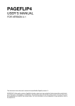
manner, it has been tested using the configurations depicted in Figures 1 to 9.
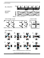
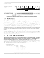
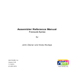
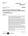
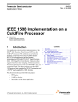
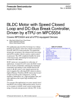
Each of the configurations defines a pin sequence, number of channels, and mode (full-step/half-step). The
bipolar and unipolar versions of any configuration are the same from the eTPU point of view, because the
generated step patterns are equal in both versions.
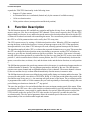
During initialization, each SM channel pin is initialized low or high to match the value of the
corresponding channel bit in the pin sequence. For example, if 0x333333 is the initial pin sequence in the
full-step drive of a 2-phase motor, then the master channel is initialized pin high, according to bit 0 of the
pin sequence, and the following slave channel is also pin high, according to bit 1 of the pin sequence (see
Figure 1). To change the initial pin states, replace the pin sequence by one of its rotated versions:
0x666666, 0xCCCCCC or 0x999999 (in etpu_sm.h file).
To generate a step, the pin sequence is rotated left or right once, depending on the motor direction (left
when direction is decremental, right when direction is incremental). The master channel pin level for the
next step is defined by the LSB of the rotated pin sequence. The pin levels of the slave channels are
determined by the next bits of the pin sequence. In full-step mode, every bit is used. In half-step mode,
every second bit is used. The figures show the effective positions of the bits that determine the pin levels
of the master and slave channels.
Using the Stepper Motor (SM) eTPU Function, Rev. 0.1
Freescale Semiconductor
3
Function Description
0x
pin_sequence
3
3
3
3
3
3
001100110011001100110011
BA
direction of rotation
generated
signals
A
B
step #
1 2 3 4 ...
motor bridge model
A
motor model
B
1 2
3 4
1
2
pole I.
3
4
IV.
II.
III.
rotor stepping
step
#1
#2
#3
#4
pole I.
II.
IV.
III.
Figure 1. . Full-step bipolar drive of a 2-phase motor.
Using the Stepper Motor (SM) eTPU Function, Rev. 0.1
4
Freescale Semiconductor
Function Description
0x
pin_sequence
3
3
3
3
3
3
001100110011001100110011
BA
direction of rotation
generated
signals
A
B
step #
1 2 3 4 ...
motor bridge model
motor model
1
2
1 2
3 4
A
B
pole I.
3
4
IV.
II.
III.
rotor stepping
step
#1
#2
#3
#4
pole I.
II.
IV.
III.
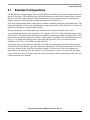
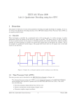
Figure 2. . Full-step unipolar drive of a 2-phase motor.
Using the Stepper Motor (SM) eTPU Function, Rev. 0.1
Freescale Semiconductor
5
Function Description
0x
pin_sequence
0
7
0
7
0
7
000001110000011100000111
D C B A
direction of rotation
generated
signals
A
B
C
D
step #
1 2 3 4 5 6 7 8 ...
motor bridge model
C
A
B
1 2
A
C
motor model
D
D
1 2
B
1
2
pole I.
3
4
IV.
II.
III.
rotor stepping
step
#1
#2
#3
#4
#6
#7
#8
pole I.
II.
IV.
III.
#5
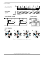
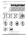
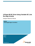
Figure 3. . Half-step bipolar drive of a 2-phase motor.
Using the Stepper Motor (SM) eTPU Function, Rev. 0.1
6
Freescale Semiconductor
Function Description
0x
pin_sequence
0
7
0
7
0
7
000001110000011100000111
D C B A
direction of rotation
generated
signals
A
B
C
D
step #
1 2 3 4 5 6 7 8 ...
motor bridge model
motor model
1
2
1 2
C
A
B
3 4
D
pole I.
3
4
IV.
II.
III.
rotor stepping
step
#1
#2
#3
#4
#6
#7
#8
pole I.
II.
IV.
III.
#5
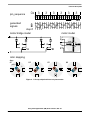
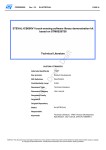
Figure 4. . Half-step unipolar drive of a 2-phase motor.
Using the Stepper Motor (SM) eTPU Function, Rev. 0.1
Freescale Semiconductor
7
Function Description
0x
pin_sequence
0
C
3
0
C
3
000011000011000011000011
F E D CB A
direction of rotation
generated
signals
A
B
C
D
E
F
step #
1 2 3 4 5 6 ...
motor model
motor bridge
A
D
B
1 2
E
C
F
3 4
5 6
1
2
3
4
I.
VI.
V.
A
D
E
B
C
F
II.
III.
IV.
5
6
rotor stepping
step
#1
I.
#2
VI.
#4
III.
V.
#5
#3
II.
IV.
#6
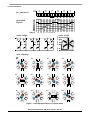
Figure 5. . Full-step bipolar drive of a 3-phase motor.
Using the Stepper Motor (SM) eTPU Function, Rev. 0.1
8
Freescale Semiconductor
Function Description
0x
pin_sequence
0
C
3
0
C
3
000011000011000011000011
F E D CB A
direction of rotation
generated
signals
A
B
C
D
E
F
step #
1 2 3 4 5 6 ...
motor bridge
motor model
1 2
3 4
5 6
1
2
3
4
I.
VI.
V.
D
A
B
E
C
F
II.
III.
IV.
5
6
rotor stepping
step
#1
I.
#2
#3
#4
II.
VI.
III.
V.
IV.
#5
#6
Figure 6. . Full-step unipolar drive of a 3-phase motor.
Using the Stepper Motor (SM) eTPU Function, Rev. 0.1
Freescale Semiconductor
9
Function Description
0x
pin_sequence
0
0
7
0
0
7
000000000111000000000111
F E D C B A
direction of rotation
generated
signals
A
B
C
D
E
F
step #
1 2 3 4 5 6 7 8 9 10 11 12 ...
motor bridge
A
motor model
D
B
1 2
E
C
3 4
F
5 6
1
2
3
4
I.
VI.
V.
A
D
E
B
C
F
II.
III.
IV.
5
6
rotor stepping
step
#1
I.
VI.
#9
#3
#4
#6
#7
#8
#10
#11
#12
III.
V.
#5
#2
II.
IV.
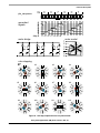
Figure 7. . Half-step bipolar drive of a 3-phase motor.
Using the Stepper Motor (SM) eTPU Function, Rev. 0.1
10
Freescale Semiconductor
Function Description
0x
pin_sequence
0
0
7
0
0
7
000000000111000000000111
F E D C B A
direction of rotation
generated
signals
A
B
C
D
E
F
step #
1 2 3 4 5 6 7 8 9 10 11 12 ...
motor model
motor bridge
1 2
3 4
5 6
1
2
3
4
I.
VI.
V.
D
A
B
E
C
F
II.
III.
IV.
5
6
rotor stepping
step
#1
I.
#2
#3
#4
#6
#7
#8
#10
#11
#12
II.
VI.
III.
V.
#5
#9
IV.
Figure 8. . Half-step unipolar drive of a 3-phase motor.
Using the Stepper Motor (SM) eTPU Function, Rev. 0.1
Freescale Semiconductor
11
C Level API for Function
0x
pin_sequence
A
A
A
A
A
A
101010101010101010101010
A
direction of rotation
generated signal
A
step #
1 2 3 4 ...
Figure 9. . General drive of a stepper motor using an external driver clocked by the eTPU.
3.2
Performance
Like all eTPU functions, the SM function performance in an application is, to some extent, dependent upon
the service time (latency) of other active eTPU channels. This is due to the operational nature of the
scheduler. When a single SM function is in use and no other eTPU channels are active, the minimum time
between any two steps must be greater than 210 eTPU instruction cycles. For the MPC5554 with a system
frequency of 128 MHz, the maximum step frequency is 304,700 steps per second. For the MCF5235 with
a system frequency of 150 MHz, the maximum step frequency is 178,500 steps per second.
When more eTPU channels are active, performance decreases. In order to ensure the correct functionality
of the SM, make sure that the slew period is longer or equal to the worst case latency of the SM master
channel.
Maximum step-frequency is influenced by compiler efficiency. The above numbers are given for guidance
only and are subject to change. For up to date information refer to the information provided in the eTPU
SM software release available from Freescale.
4
C Level API for Function
The following routines provide easy access to the SM function for the application developer. Use of these
functions eliminate the need to directly control the eTPU registers. There are six functions added to the
application programming interface (API). The routines can be found in the etpu_sm.h and
etpu_sm.c files, which should be included in the link file along with the top level development file(s).
These routines use standard eTPU utilities, that are located in the etpu_util.h and etpu_util.c
files. The routines will be described in order and are listed below:
• Initialization Function:
int32_t fs_etpu_sm_init( uint8_t
uint8_t
int24_t
int24_t
int24_t
channel,
configuration,
start_position,
start_period,
slew_period,
Using the Stepper Motor (SM) eTPU Function, Rev. 0.1
12
Freescale Semiconductor
C Level API for Function
const uint16_t *p_accel_tbl,
uint16_t accel_tbl_size )
•
Change Operation Functions:
void fs_etpu_sm_enable( uint8_t channel, uint8_t priority)
void fs_etpu_sm_disable( uint8_t channel, uint8_t polarity)
void fs_etpu_sm_set_dp( uint8_t channel, int24_t desired_position)
void fs_etpu_sm_set_sp( uint8_t channel, int24_t slew_period)
•
Value Return Functions:
int24_t fs_etpu_sm_get_dp( uint8_t channel)
int24_t fs_etpu_sm_get_cp( uint8_t channel)
uint8_t fs_etpu_sm_get_flags( uint8_t channel)
4.1
Initialization Function
4.1.1
int32_t fs_etpu_sm_init(...)
This routine is used to initialize the eTPU channels for the SM function. The SM eTPU channels must be
initialized once, and then can be repeatedly enabled and disabled by fs_etpu_sm_enable() and
fs_etpu_sm_disable() functions. This function has the following parameters:
• channel (uint8_t): This is the SM master channel number. This parameter should be assigned a
value of 0-31 for ETPU_A, and 64-95 for ETPU_B, with respect to the number of following slave
channels. The slave channels are defined immediately after the master, in numeric order.
• configuration (uint8_t): This is the pre-defined configuration parameter. This parameter should
be assigned a value of:
— FS_ETPU_SM_2PHASE_FULL_STEP
— FS_ETPU_SM_2PHASE_HALF_STEP
— FS_ETPU_SM_3PHASE_FULL_STEP
— FS_ETPU_SM_3PHASE_HALF_STEP
— FS_ETPU_SM_EXT_DRIVER
The pre-defined configurations correspond to the examples described in Section 3.1, “Example
Configurations”, and pre-define the number of channels used, the pin sequences, and the mode
(full-step/half-step). If an application requires a change to a configuration, edit the pre-defined values in
the file etpu_sm.h.
• start_position (int24_t): This is the starting current_position value.
• start_period (int24_t): This is the start period as a number of TCR1 ticks. The start period is the
first and last step period of a movement. If an application uses frequencies in Hz, instead of
periods in TCR1 cycles, one of the following expressions can be used instead of start_period:
etpu_a_tcr1_freq/start_frequency;
Using the Stepper Motor (SM) eTPU Function, Rev. 0.1
Freescale Semiconductor
13
C Level API for Function
etpu_b_tcr1_freq/start_frequency;
•
slew_period (int24_t): This is the slew period as a number of TCR1 ticks. The slew period is the
step period when the motor rotates at max speed. The slew period is the shortest period of a
movement. If an application uses frequencies in Hz, instead of periods in TCR1 cycles, one of the
following expressions can be used instead of slew_period:
etpu_a_tcr1_freq/slew_frequency;
etpu_b_tcr1_freq/slew_frequency;
•
•
4.2
4.2.1
accel_tbl (const uint16_t*): This parameter is the pointer to the acceleration table. The
acceleration table is an array of unsigned fract16. The nth step period results from the fractional
multiplication of the start_period and accel_tbl[n].
accel_tbl_size (uint16_t): This parameter is the acceleration table size as a number of 16-bit
acceleration steps.
Change Operation Functions
void fs_etpu_sm_enable(...)
This routine is used to enable the SM eTPU channels. This function has the following parameters:
• channel (uint8_t): This is the SM master channel number. This parameter should be assigned a
value of 0-31 for ETPU_A, and 64-95 for ETPU_B, with respect to the number of following slave
channels. The slave channels are defined immediately after the master, in numeric order.
• priority (uint8_t): This is the priority to assign to the SM function. The eTPU priority definitions
are defined in etpu_utils.h:
— FS_ETPU_PRIORITY_HIGH
— FS_ETPU_PRIORITY_MIDDLE
— FS_ETPU_PRIORITY_LOW
— FS_ETPU_PRIORITY_DISABLED
4.2.2
void fs_etpu_sm_disable(...)
This routine is used to disable the SM eTPU channels. This function has the following parameters:
• channel (uint8_t): This is the SM master channel number. This parameter should be assigned a
value of 0-31 for ETPU_A, and 64-95 for ETPU_B, with respect to the number of following slave
channels. The slave channels are defined immediately after the master, in numeric order.
• polarity (uint8_t): This is the polarity of the generated signals. This parameter can be assigned a
value of:
— FS_ETPU_SM_ACTIVE_HIGH
— FS_ETPU_SM_ACTIVE_LOW
Using the Stepper Motor (SM) eTPU Function, Rev. 0.1
14
Freescale Semiconductor
C Level API for Function
4.2.3
void fs_etpu_sm_set_dp(uint8_t channel, int24_t
desired_position)
This function sets where to move the stepper motor, and the command for movement. This function has
the following parameters:
• channel (uint8_t): This is the SM master channel number. This parameter must be assigned the
same value that is assigned to the channel parameter in the initialization routine. If there are more
SMs running simultaneously on the eTPU(s), the channel parameter distinguishes which SM
function is accessed.
• desired_position (int24_t): This is the desired position that the motor should move to.
After etpu_sm_set_dp(...) is called, the motor moves until there is a match between the
current_position and the desired_position. Also, the etpu_sm_set_dp function can be called at any
time, even when the motor is stepping towards another value. The SM function will automatically take care
of slowing the motor, reversing the direction (if necessary), and accelerating towards the new
desired_position as needed.
4.2.4
void fs_etpu_sm_set_sp(uint8_t channel, int24_t
slew_period)
The slew period parameter specifies the minimum step period of the motor (and therefore its maximum
speed).
• channel (uint8_t): This is the SM master channel number. This parameter must be assigned the
same value as was assigned to the channel parameter in the initialization routine. If there are more
SMs running simultaneously on the eTPU(s), the channel parameter distinguishes which SM
function is accessed.
• slew_period (int24_t): Slew period as a number of TCR1 ticks. If the application uses
frequencies in Hz, instead of periods in TCR1 cycles, one of the following expressions can be
used instead of slew_period:
etpu_a_tcr1_freq/slew_frequency;
etpu_b_tcr1_freq/slew_frequency;
The slew_period parameter is used under two circumstances:
1. The end of the acceleration table is reached.
2. The period value, obtained from the fractional multiplication of the start_period value by an
acceleration parameter (from the table), is less than slew_period. This allows the slew_period to
be used to limit the maximum speed of a particular motor when multiple motors are sharing a
common acceleration table.
The slew_period also allows a motor to make moves of the same length at different speeds, without
requiring a reprogramming of the acceleration table.
Using the Stepper Motor (SM) eTPU Function, Rev. 0.1
Freescale Semiconductor
15
C Level API for Function
NOTE
slew_period should only be changed between moves and not while the
motor is running.
4.3
4.3.1
Value Return Functions
int24_t fs_etpu_sm_get_dp(uint8_t channel)
This function reads the desired_position and contains the following parameter:
• channel (uint8_t): This is the SM master channel number. This parameter must be assigned the
same value as was assigned to the channel parameter in the initialization routine. If there are more
SMs running simultaneously on the eTPU(s), the channel parameter distinguishes which SM
function is accessed.
The value of the desired_position is returned as an int24_t.
4.3.2
int24_t fs_etpu_sm_get_cp(uint8_t channel)
This function reads the current_position of the SM that can be used for program control when compared
against the desired_position or some other value. This function has the following parameter:
• channel (uint8_t): This is the SM master channel number. This parameter must be assigned the
same value as was assigned to the channel parameter in the initialization routine. If there are more
SMs running simultaneously on the eTPU(s), the channel parameter distinguishes which SM
function is accessed.
The value of the current_position is returned as an int24_t.
4.3.3
uint8_t fs_etpu_sm_get_flags(uint8_t channel)
This function reads the status flags of the SM. There are the following flags:
— STEPPING - indicates if the motor is currently stepping or not
— DIRECTION - distinguishes if the motor is going in a decremental (left) direction or an
incremental (right) direction
— SLEW - indicates if the motor is currently in a slew rate
This function has the following parameter:
• channel (uint8_t): This is the SM master channel number. This parameter must be assigned the
same value as was assigned to the channel parameter in the initialization routine. If there are more
SMs running simultaneously on the eTPU(s), the channel parameter distinguishes which SM
function is accessed.
The flags are returned as an int8_t.
The following examples show how the returned flags value can be used for program control. The
flag masks and flag values defined in etpu_sm.h are used:
Using the Stepper Motor (SM) eTPU Function, Rev. 0.1
16
Freescale Semiconductor
TPU-Compatible C Level API
if ((flags & FS_ETPU_SM_STEPPING)
if ((flags & FS_ETPU_SM_STEPPING)
== FS_ETPU_SM_STEPPING_ON)
== FS_ETPU_SM_STEPPING_OF)
{...}
{...}
if ((flags & FS_ETPU_SM_DIRECTION) == FS_ETPU_SM_DIRECTION_DEC) {...}
if ((flags & FS_ETPU_SM_DIRECTION) == FS_ETPU_SM_DIRECTION_INC) {...}
if ((flags & FS_ETPU_SM_SLEW)
if ((flags & FS_ETPU_SM_SLEW)
5
== FS_ETPU_SM_SLEW_ON)
== FS_ETPU_SM_SLEW_OFF)
{...}
{...}
TPU-Compatible C Level API
The TPU-compatible API provides backward-compatibility from eTPU to TPU. The following functions
allow control of the eTPU SM function using the TPU TSM API function calls:
• Initialization Function:
void tpu_tsm_init( struct TPU3_tag *tpu,
UINT8
channel,
UINT8
priority,
INT16
start_position,
UINT16 table_size_index,
UINT16 slew_period,
UINT16 start_period,
UINT16 pin_sequence,
UINT8
number_channels,
UINT16 *table,
UINT8
table_size)
•
Change Operation Functions:
void tpu_tsm_mov(struct TPU3_tag *tpu, UINT8 channel, UINT16 position)
•
Value Return Functions:
UINT16 tpu_tsm_rd_dp(struct TPU3_tag *tpu, UINT8 channel);
UINT16 tpu_tsm_rd_cp(struct TPU3_tag *tpu, UINT8 channel);
5.1
5.1.1
Initialization Function
void tpu_tsm_init
This routine will initialize the channels of the eTPU for the SM function, in the same way as for the TPU
TSM function. This function has the following parameters:
• *tpu—Not used.
• channel—The channel number of the SM master channel.
• priority—The priority level which is assigned to all channels used for this SM function. This
parameter should be assigned a value of: FS_ETPU_PRIORITY_HIGH,
FS_ETPU_PRIORITY_MIDDLE, or FS_ETPU_PRIORITY_LOW.
Using the Stepper Motor (SM) eTPU Function, Rev. 0.1
Freescale Semiconductor
17
TPU-Compatible C Level API
•
•
•
•
•
•
•
•
5.2
5.2.1
start_position—A 16-bit integer which establishes the initial value for both the desired position
and the current position. This is efficient, since both values need to be set to the same value when
the SM function is initialized.
table_size_index—Combines the table size and the table index values into a single 16-bit input.
The first 8 bits, the table size, is the number of steps defined in the acceleration table. The table
index is set in the last 8 bits of this parameter and must be set to the value of zero.
slew_period—Combines the slew period with the 1-bit "S" value. The slew period value must be
shifted left by 1 bit, after encoding into a hex value. For example, an original value of $2000 will
be encoded as $4000. The least significant bit is an "S" bit and must always be written as zero
(and only at initialization).
start_period—Combines the start period with the 1-bit "A" value. The start period value must be
shifted left by 1 bit after encoding into a hex value. For example, an original value of $6800 will
be encoded as $D000. The least significant bit is an "A" bit. A value of 0 will initialize a
two-channel TSM function, and a value of 1 will initialize a four-channel function. This value
must not be changed after initialization.
pin_sequence—Determines the step patterns that are output on two or four TPU pins. Two
channel and four channel example values are $3333, and $E0E0 respectively.
number_channels—Used with the master channel designation to determine which channels will
be the parameter table channels for the TSM function. Either a two- or four-channel designation is
valid. The master channel is included in this number.
*table—The pointer to the acceleration table.
table_size—Not used.
Change Operation Functions
void tpu_tsm_mov(struct TPU3_tag *tpu, UINT8 channel,
UINT16 position)
This function will designate where to move the stepper motor. This is accomplished by the following input
parameters:
• *tpu—Not used.
• channel—The channel number of the SM master channel.
• position—The value of the new desired position.
Using the Stepper Motor (SM) eTPU Function, Rev. 0.1
18
Freescale Semiconductor
Example Use of Function
5.3
5.3.1
Value Return Functions
UINT16 tpu_tsm_rd_dp(struct TPU3_tag *tpu, UINT8
channel)
This routine will read the value of the desired position, which is used for program control when compared
against some other value.
• *tpu—Not used.
• channel—The channel number of the SM master channel.
The value of the desired position is returned as an UINT16 function.
5.3.2
UINT16 tpu_tsm_rd_cp(struct TPU3_tag *tpu, UINT8
channel)
This routine will read the value of the current position, which is used for program control when compared
against some other value.
• *tpu—Not used.
• channel—The channel number of the SM master channel.
The value of the current position is returned as an UINT16 function.
6
Example Use of Function
6.1
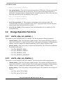
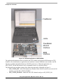
Demo Application
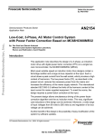
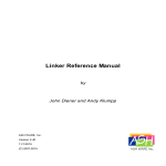
This section describes an example application, which is created using Metrowerks CodeWarior 4.0 and
runs on MCF523x Evaluation Board (MCF523xEVB). Even if no stepper motor is connected, the stepping
pattern is clearly visible on six LEDs that are connected to eTPU channels 8 to 13.
Using the Stepper Motor (SM) eTPU Function, Rev. 0.1
Freescale Semiconductor
19
Example Use of Function
FreeMaster
LEDs
FreeMaster
RS-232
Interface
BDM
Interface
Figure 10. . SM demo application on MCF523xEVB.
The application demonstrates how to initialize the eTPU module and assign the SM function to eTPU
channels. After initialization, an application state machine is started. Within the state machine, the SM
function is enabled and disabled based on ON/OFF switch moves. When the application is in
APP_STATE_ON the SM function can be commanded to move to a desired position.
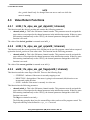
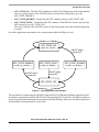
The application state machine consists of the following states and is illustrated in Figure 11:
• APP_STATE_OFF—SM eTPU channels are disabled. If the ON/OFF switch is moved to the ON
position, go to the APP_STATE_ENABLE.
• APP_STATE_ENABLE—Enable the SM eTPU channels and go to APP_STATE_ON.
Using the Stepper Motor (SM) eTPU Function, Rev. 0.1
20
Freescale Semiconductor
Example Use of Function
•
•
•
APP_STATE_ON—The SM eTPU channels are enabled. The SM function can be commanded to
move to a given position. If the ON/OFF switch is moved to the OFF position, go to the
APP_STATE_DISABLE.
APP_STATE_DISABLE—Disable the SM eTPU channels and go to APP_STATE_OFF.
APP_STATE_FAULT—Disable the SM eTPU channels. If the ON/OFF switch is moved to the
OFF position, go to APP_STATE_OFF.
This state is entered if the ON/OFF switch is in the ON position at the time when the application
is started.
Out of the application state machine, the current position and the SM flags are read.
APP_STATE_ON
fs_etpu_sm_set_dp(…);
ON/OFF switch
moved OFF
APP_STATE_ENABLE
APP_STATE_FAULT
APP_STATE_DISABLE
fs_etpu_sm_enable(…);
fs_etpu_sm_disable(…);
fs_etpu_sm_disable(…);
ON/OFF switch
moved ON
ON/OFF switch
moved OFF
APP_STATE_OFF
Figure 11. . Demo application state machine.
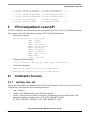
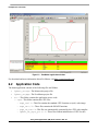
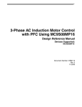
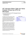
The user interface is made using the ON/OFF switch on MCF523xEVB and FreeMaster application on PC.
FreeMaster communicates with the MCF523xEVB through the RS-232 serial line. FreeMaster enables to
set the desired position and displays the current position and SM flags. Moreover, FreeMaster depicts the
desired and the current positions in a time chart.
Using the Stepper Motor (SM) eTPU Function, Rev. 0.1
Freescale Semiconductor
21
Example Use of Function
Figure 12. . FreeMaster application window.
For download and more information about FreeMaster visit http://www.freescale.com.
6.2
Application Code
The demo application consists of the following files and folders:
• 3phase_sm.mcp—The Metrowerks project file.
• 3phase_sm.pmp—The FreeMaster project file.
• src —This folder contains the application source code:
— etpu - This folder contains the eTPU files.
– etpu_set1.h - This file contains the standard eTPU function set (set1) code image.
– etpu_sm.c/.h - These files contains the SM API functions.
– etpu_sm_auto.h - This file was automatically generated by the eTPU code compiler.
– 3phase_sm_etpu_gct.c/.h - These files contain initialization of eTPU for this
Using the Stepper Motor (SM) eTPU Function, Rev. 0.1
22
Freescale Semiconductor
Example Use of Function
application. They were originally generated by the eTPU Graphical Configuration Tool.
– etpu_util.c/.h - These files contain useful macros and prototypes for using the
eTPU.
– typedefs.h - This file contains type definitions.
— pcmaster - This folder contains FreeMaster routines for MCF523x.
•
•
— init - This folder contains MCF523x header files, etc.
— main.c/.h - This is the main application file and its header file.
— vectors.s - This file contains the vector table.
— int_handlers.c - This file contains the general interrupt handlers.
pcmaster - This folder contains FreeMaster HTML page source.
lcf - This folder contains the Metrowerks linker command files, MCF523xEVB configuration,
etc.
The eTPU initialization consists of two function calls. First, the my_system_etpu_init() function
is called, and second, after initialization of all other peripherals, the eTPU is started by
my_system_etpu_start(). Both my_system_etpu_init() and
my_system_etpu_start() functions are generated by eTPU Graphical Configuration Tool and are
included in 3phase_sm_etpu_gct.c file. Graphical Configuration Tool can be downloaded from
http://www.freescale.com.
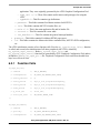
6.2.1
Function Calls
fs_etpu_sm_init(
/* channel
*/
SM0_A_MASTER,
/* configuration
*/
FS_ETPU_SM_3PHASE_HALF_STEP,
/* start_position
*/
0,
/* start_period
*/
etpu_a_tcr1_freq/StartFrequency,
/* start_period
*/
etpu_a_tcr1_freq/StartFrequency,
/* slew_period
*/
etpu_a_tcr1_freq/SlewFrequency,
/* p_accel_tbl
*/
accel_tbl,
/* accel_tbl_size
*/
SM_ACCEL_TABLE_SIZE
/* channel
*/
SM0_A_MASTER,
/* priority
*/
FS_ETPU_PRIORITY_MIDDLE,
/* configuration
*/
FS_ETPU_SM_3PHASE_HALF_STEP
);
fs_etpu_sm_enable(
Using the Stepper Motor (SM) eTPU Function, Rev. 0.1
Freescale Semiconductor
23
Summary and Conclusions
);
fs_etpu_sm_disable(
/* channel
*/
SM0_A_MASTER,
/* configuration
*/
FS_ETPU_SM_3PHASE_HALF_STEP
/* polarity
*/
FS_ETPU_SM_ACTIVE_HIGH
*/
SM0_A_MASTER,
);
fs_etpu_sm_set_dp(
/* channel
/* desired_position */
DesiredPosition
);
CurrentPosition = fs_etpu_sm_get_cp(
/* channel
*/
SM0_A_MASTER,
);
Flags = fs_etpu_sm_get_flags(
/* channel
*/
SM0_A_MASTER,
);
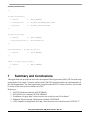
7
Summary and Conclusions
This application note provides the user with a description of the stepper motor (SM) eTPU function usage
and examples. The simple C interface routines to the SM eTPU function enable easy implementation of
the SM in applications. The demo application is targeted at the MCF523x family of devices, but it could
be easily reused with any device that has an eTPU.
References:
1. MCF5235 Reference Manual, MCF5235RM/D
2. M523xEVB User’s Manual, M5235EVBUM/D
3. FreeMaster web page, http://www.freescale.com, search keyword “FreeMaster”
4. Enhanced Time Processing Unit Reference Manual, ETPURM/D
5. eTPU Graphical Configuration Tool, http://www.freescale.com, search keyword “ETPUGCT”
Using the Stepper Motor (SM) eTPU Function, Rev. 0.1
24
Freescale Semiconductor
Revision History
8
Revision History
Table 1 provides a revision history of this document.
Table 1. Revision History
Rev
Number
Date of
Release
Substantive Changes
0.1
04/2006
In section 3.2, changed 304.700 and 178.500 steps to 304,700 and 178,500 steps.
0
10/2004
Initial customer-release version.
Using the Stepper Motor (SM) eTPU Function, Rev. 0.1
Freescale Semiconductor
25
How to Reach Us:
Home Page:
www.freescale.com
E-mail:
[email protected]
USA/Europe or Locations Not Listed:
Freescale Semiconductor
Technical Information Center, CH370
1300 N. Alma School Road
Chandler, Arizona 85224
+1-800-521-6274 or +1-480-768-2130
[email protected]
Europe, Middle East, and Africa:
Freescale Halbleiter Deutschland GmbH
Technical Information Center
Schatzbogen 7
81829 Muenchen, Germany
+44 1296 380 456 (English)
+46 8 52200080 (English)
+49 89 92103 559 (German)
+33 1 69 35 48 48 (French)
[email protected]
Japan:
Freescale Semiconductor Japan Ltd.
Technical Information Center
3-20-1, Minami-Azabu, Minato-ku
Tokyo 106-0047, Japan
0120 191014 or +81 3 3440 3569
[email protected]
Asia/Pacific:
Freescale Semiconductor Hong Kong Ltd.
Technical Information Center
2 Dai King Street
Tai Po Industrial Estate
Tai Po, N.T., Hong Kong
+800 2666 8080
[email protected]
For Literature Requests Only:
Freescale Semiconductor Literature Distribution Center
P.O. Box 5405
Denver, Colorado 80217
1-800-441-2447 or 303-675-2140
Fax: 303-675-2150
[email protected]
Information in this document is provided solely to enable system and
software implementers to use Freescale Semiconductor products. There are
no express or implied copyright licenses granted hereunder to design or
fabricate any integrated circuits or integrated circuits based on the
information in this document.
Freescale Semiconductor reserves the right to make changes without further
notice to any products herein. Freescale Semiconductor makes no warranty,
representation or guarantee regarding the suitability of its products for any
particular purpose, nor does Freescale Semiconductor assume any liability
arising out of the application or use of any product or circuit, and specifically
disclaims any and all liability, including without limitation consequential or
incidental damages. “Typical” parameters that may be provided in Freescale
Semiconductor data sheets and/or specifications can and do vary in different
applications and actual performance may vary over time. All operating
parameters, including “Typicals”, must be validated for each customer
application by customer’s technical experts. Freescale Semiconductor does
not convey any license under its patent rights nor the rights of others.
Freescale Semiconductor products are not designed, intended, or authorized
for use as components in systems intended for surgical implant into the body,
or other applications intended to support or sustain life, or for any other
application in which the failure of the Freescale Semiconductor product could
create a situation where personal injury or death may occur. Should Buyer
purchase or use Freescale Semiconductor products for any such unintended
or unauthorized application, Buyer shall indemnify and hold Freescale
Semiconductor and its officers, employees, subsidiaries, affiliates, and
distributors harmless against all claims, costs, damages, and expenses, and
reasonable attorney fees arising out of, directly or indirectly, any claim of
personal injury or death associated with such unintended or unauthorized
use, even if such claim alleges that Freescale Semiconductor was negligent
regarding the design or manufacture of the part.
Freescale™ and the Freescale logo are trademarks of Freescale
Semiconductor, Inc. All other product or service names are the property
of their respective owners.© Freescale Semiconductor, Inc. 2004, 2006. All
rights reserved.
AN2869
Rev. 0.1
04/2006