1
Introduction to Open Source BDM
Open Source BDM Interface Users Manual
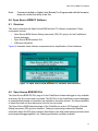
1.0 Introduction to Open Source BDM
This document describes an Open Source programming and debugging development tool
designed to work with Freescale HCS08 microcontrollers. Called Open Source BDM, it can be
obtained from the 8-bit message board at http://forums.freescale.com. While there is no support
for Open Source BDM from Freescale, the Open Source BDM is provided with all required
source code for both hardware and software components. Because it is open source, the
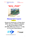
source code can be used and/or modified from its original design free of charge. Figure 1
provides a pictorial overview of the typical connections required for programming and
debugging using the Open Source BDM. A PC connects to the Open Source BDM PCB, in turn
the PCB is connected to a Programming/Debug target. In this example, the GB60
demonstration boards are being programmed and debugged.
Figure 1. Debugging with Open Source BDM
Open Source BDM, with its hardware and software components, provides a transparent
connection between a computer running CodeWarrior Development Studio for HCS08 version
5.0 to a Freescale HCS08 microcontroller via the microcontrollers BKGD pin. With a connection
to the BKGD pin, the Open Source BDM enables debuggers and other software tools to
communicate with the microcontroller including downloading of user code into the
1
Open Source BDM Interface Users Manual
microcontroller’s on-chip flash. Programming and debugger functionality is made possible by the
HCS08 microcontroller’s Background Debug Controller (BDC) and In-Circuit Emulator (ICE)
Debug (DBG) modules.
1.1 About the HCS08 BDC/ICE Debug Module
HCS08 microcontrollers contain a single-wire background debug interface, supporting in-circuit
programming of on-chip nonvolatile memory and sophisticated non-intrusive debug capabilities.
The BKGD pin on HCS08 devices provides this single-wire background debug interface to the
on-chip BDC and ICE Debug modules. See the Development Tools chapter of any HCS08 data
sheet for more information about both the BDC and ICE Debug modules. While the interface is
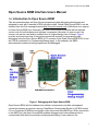
single wire, typically a 6-pin connector, a BDM port is used to interface with the target. Figure 2
depicts the 6-pin BDM port.
Figure 2 . Target 6-Pin Connector for BKGD Pin
The primary function of this pin is for bidirectional serial communication of active background
mode commands and data. During reset, this pin is used to select between starting in active
background mode or starting the user’s application program. Additionally, this pin requests a
timed sync response pulse, allowing a host development tool to determine the correct clock
frequency for background debug serial communications.
BDC commands are sent serially from a host computer to the BKGD pin of the target HCS08
MCU. All commands and data are sent MSB-first using a custom BDC communications protocol.
Two groups of BDC commands are listed below. A complete list of these commands is provided
in the Development Tools chapter.
1. Active Background Mode Commands: These commands allow the CPU registers to be
read or written. Users can also trace one user instruction at a time, or begin the user
program in this mode.
2. Non-intrusive Commands: These commands permit read or write of MCU memory
locations, or access status and control registers within the background debug
controller. Non-intrusive commands can be executed at any time.
With a single-wire background debug interface, a relatively simple interface pod is used to
translate commands from a host computer into commands for the BDC. In the case of the Open
Source BDM, a Low-speed (LS) universal serial bus (USB) interface is used to communicate
2
Introduction to Open Source BDM
between the host PC and the pod. Functionality provided by the BDC and ICE DBG modules
include:
•
•
Single pin for mode selection and background communications
BDC registers not located in the memory map
•
•
•
•
•
•
•
•
SYNC command to determine target communications rate
Non-intrusive commands for memory access
Active background mode commands for CPU register access
GO and TRACE1 commands
BACKGROUND command can wake CPU from Stop or Wait modes
One hardware address breakpoint built into BDC
Oscillator runs in Stop mode when BDC is enabled
COP watchdog disabled while in Active Background mode
•
Features of the debug module (DBG) include:
— Two trigger comparators: Two address + read/write (R/W) or One full address + data
+ R/W
— Flexible 8-word by 16-bit first-in, first-out (FIFO) buffer for capture information:
change-of-flow addresses or event-only data
— Two types of breakpoints: Tag breakpoints for instruction opcodes and force
breakpoints for any address access
— Nine trigger modes
1.2 Scope of the User Manual
This documentation describes the Open Source BDM solution. The description provides
sufficient detail, enabling the Open Source community to update, change, and maintain the Open
Source BDM. This user manual describes the the organization and operation of the following:
•
•
•
•
Open Source BDM Generic Debug Instrument (GDI) DLL plug-in for the CodeWarrior
hiwave debugger
Open Source BDM interface DLL and USB driver (libusb.lib)
HC908JB16 USB/BDM firmware
Open Source BDM PCB hardware
1.3 Open Source BDM Overview
While using the Open Source BDM, supplemental understanding of a debugger pod may be
required with possibly more user maintenance to provide a low-cost alternative for development
tools. The Open Source BDM software and hardware were developed to support existing and
future HCS08 devices. It is designed to provide maximum accuracy and performance for HCS08
devices. Open Source BDM is compatible with CodeWarrior Studio HCS08 version 5.0, and
currently supports the following HCS08 families:
3
Open Source BDM Interface Users Manual
•
•
•
•
GB60
AW6
QG8
RCx
As other HCS08 families are developed and released, the open source community may have to
modify the Open Source BDM along with installation of CodeWarrior Studio HCS08 version 5.0
service packs. Other features of the Open Source BDM are:
•
•
•
•
•
•
•
•
•
•
•
•
•
•
•
Open source distribution
Low-cost development tools
Designed for the modern and widely available USB interface
Firmware developed with the HCS08 CodeWarrior Special Edition version
Supports targets with operating voltages from 1.8 to 5.0V
Supports target bus speeds from 1.0 to 20MHz
Double-side PCB uses mostly though-hole design for ease of assembly
PCB can optionally supply 5.0V power to the MCU target board
PCB has an optional 16-pin MONO8 header to program the JB16
PC USB DLL drivers source code is provided in ANSI C
JB16 firmware source is mostly C with some assembly for time critical operations
Firmware can be flash programmed using USB and Freescale interface. See AN2399 these procedures are documented within this document.
Windows USB drivers included using Open Source LIBUSB USB drivers
Uses a JB16 MCU with 12MHz crystal clock source
Documented API for easy integration into debuggers
As indicated, all the Open Source BDM source code is provided without charge. In addition, the
Open Source BDM hardware uses low-cost components and is very simple to assemble.
Unassembled PCB cost approximately under five U.S. dollars and the components can also be
obtained for less than U.S. five dollars, depending on volume. Subsequent sections provide a
detailed description of both the Open Source BDM hardware and software.
1.4 Open Source BDM Block Diagram
To better understand the implementation of the Open Source BDM, Figure 3 delineates the Open
Source BDM solution into its most basic components. The diagram illustrates part of the Open
Source BDM IP residing on the PC host for the debugging software and some resides on the
Open Source BDM PCB.
At the time of release, the Open Source BDM is supported by the version 5.0 release of
CodeWarrior Development Studio for Freescale HC(S)08 Microcontrollers. The Studio provides
both a software development IDE and a debugger.
4
Introduction to Open Source BDM
Figure 3. Block Diagram
Figure 3 illustrates five primary components, four software in nature and one hardware; these
are itemized below. All of the software components are intended to be used as binaries by
majority of users. For those who would like to look deeper, the source code of the JB16 firmware
and the Open Source BDM interface DLL is provided in Table 1.
5
Open Source BDM Interface Users Manual
Table 1 Open Source BDM IP Components
Component
Description/Interfaces
Available/Comments
Open Source
BDM GDI driver
File - OpenSourceBDM_gdi.dll
Software interfacing with the CW V5.0
debugger GDI interface, providing function
call to the Open Source BDM USB driver.
This software is available only as object
code in the form of a DLL.
Open Source
BDM USB driver
File - OpenSourceBDM.dll
Software interfacing with the Open Source
BDM GDI driver, providing function calls to the
Windows USB drivers. This file is also
required for the PC when it detects the Open
Source BDM PCB as a new USB device on
the PC USB port.
This software is available as both object
(DLL) and source code. The DLL is
provided in an Open Source BDM USB
install package. Point the PC Hardware
Wizard to the USB install package when
the PC detected the Open Source BDM
PCB.
Windows USB
drivers
File - libusb.lib
Software used by the Open Source BDM USB
driver it interfaces to PC USB ports.
This USB library is compiled with the
Open Source BDM USB driver and is also
part of the Open Source BDM USB install
package. The source code for libusb can
be found at (http://libusb.sourceforge.net/)
JB16 USB/BDM
firmware
File - OpenSourceBDM.s19
Software running on the JB16 that receives
commands via USB from the PC and converts
them into commands as defined by the BDC.
These command are serial outputted - “bit banged” - by the JB16 using port pins to drive
the BKGD pin on the user’s target.
This file is provide as a S-recorded and
need to be programmed the the JB16 onchip flash
Open Source
BDM PCB
hardware
PCB: OpenSourceBDM Pod ver. 1.0
This hardware contains the JB16 and circuitry,
clock, and power to provide the interface to
the program/debug target.
All schematics and gerber files for the
Open Source BDM PCB is provided along
with a Bill of Materials (BOM). Also
included is a complete HW description
which enables you to build the interface
1.5 Open Source BDM Package
This section describes the contents of the Open Source BDM package. The package is
distributed in zip file and includes both release and development folders. The development files
folder contains source files while the release files folder contains only binary release files. A
detailed discussion is provided for each of these items in the next sections. An illustration of the
unzipped Open Source BDM package directory structure is provided in Figure 4.
6
Open Source BDM PCB Hardware and MC68HC908JB16
Figure 4. Unzipped Open Source BDM Package
1.6 Support and Licensing
Open Source BDM is not supported by Freescale; it is open source. Any bugs, enhancements,
or support questions should be addressed through the Open Source BDM forum. Open Source
BDM has been thoroughly tested, but there are no guarantees about error-free operation. All of
the work, with exception of the GDI DLL, is available to anyone under the GNU general public
license. The Open Source BDM is a deriviative project of the TBMDL project.
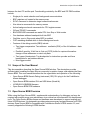
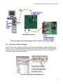
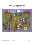
2.0 Open Source BDM PCB Hardware and MC68HC908JB16
Photos of the Open Source BDM PCB top and bottom sides are provided in Figure 5. The bottom
side shows the MC68HC908JB16 used to decode incoming USB messages into BDC
commands and then bit-bang the BDC commands to a target. The Open Source BDM PCB is
designed with many desirable features, making it a robust development tool. The following list is
a summary of those features:
•
•
•
Based on MC68HC908JB16 MCU from Freescale with a 12MHz crystal
Provides circuitry to facilitate Firmware upgrades of the MC68HC908JB16
USB interface with a type B USB connector
7
Open Source BDM Interface Users Manual
•
•
•
•
PCB provides optional circuitry used to update the Open Source BDM PCB to support
other targets besides HCS08 devices
Double-side PCB uses mostely through-hole design for ease of assembly
PCB can optionally supply 5.0V power to the MCU target board
PCB has an optional 16-pin MONO8 header to program the JB16
Top Side
Bottom Side
Figure 5. Open Source BDM PCB
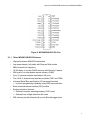
2.1 MC68HC908JB16 Overview
The Open Source BDM is based on MC68HC908JB16 MCU from Freescale. The
MC68HC908JB16 provides:
•
•
•
Relatively low-cost HC08
A low speed USB 2.0 compatible interface
Surface mount 28-pin SOIC package
Figure 6 provides quick reference of the MC68HC908JB16 pinout.
8
Open Source BDM PCB Hardware and MC68HC908JB16
Figure 6. MC68HC908JB16 Pin-Out
2.1.1 Other MC68HC908JB16 Features
•
•
•
•
•
•
•
•
•
•
•
High-performance M68HC08 architecture
Low-power design; fully static with Stop and Wait modes
6MHz internal bus frequency
16,384 bytes of on-chip FLASH memory with Security1 feature
384 bytes of on-chip random access memory (RAM)
Up to 21 general-purpose input/output (I/O) pins
Two 16-bit, 2-channel timer interface modules (TIM1 and TIM2)
Universal Serial Bus specification 2.0 low-speed functions
— In-circuit programming capability using USB communication
Serial communications interface (SCI) module
System protection features:
— Optional computer operating properly (COP) reset
— Optional Low-voltage detection with reset
IRQ interrupt pin with internal pull-up and Schmidt-trigger input
9
Open Source BDM Interface Users Manual
2.1.2 MC68HC908JB16 USB
Open Source BDM is designed to use USB as the means of talking to the computer because:
•
USB provide plug and play functionality
•
USB can provide power to the Open Source BDM PCB and the target, avoiding the
requirement of an additional power supplies
— By routing the USB power to the BDM connector, the Open Source BDM PCB can
also provide 5.0V power to the target board
The LS USB peripheral of the MC68HC908JB16 provides sufficient USB functionality to
facilitate the Open Source BDM operations. The MC68HC908JB16 USB features include:
•
•
1.5Mbps data rate
On-chip 3.3V regulator
•
Three Endpoints
— Endpoint 0 with 8-byte transmit buffer and 8-byte receive buffer
— Endpoint 1 with 8-byte transmit buffer
— Endpoint 2 with 8-byte transmit buffer and 8-byte receive buffer
2.1.3 MC68HC908JB16 Development
•
•
The development environment and the hiwave debugger looks the same for both HC08
and HC(S)08
The development environment is available free of charge for the size of project
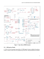
2.2 Open Source BDM PCB
The schematics are provided for the Open Source BDM PCB in Figure 7. The schematics
provide details of the power and clocking connections for the Open Source BDM PCB. These
schematics also show various jumpers settings. The optional circuity is not discussed in this
document.
Besides the HC908JB16, the schematic of the Open Source BDM interface shows several main
parts:
•
•
10
A USB interface with jumper options
— Options to program the HC908JB16
— Options for standard Open Source BDM operation
BDM interface driver based on 74LVC1T45 buffer with tri-state outputs
Open Source BDM PCB Hardware and MC68HC908JB16
Figure 7 . Open Source BDM Schematic
2.2.1 USB interface Details
A 1.5 KΩ (±1%) pull-up resistor is provided on D-USB signal. A jumper is added to the pull-up
resistor in order to assist in the ICP programming of the JB16, using techniques from AN2399.
11
Open Source BDM Interface Users Manual
Note:
PCB is provided with footprint for the USB B connector. This is actually in violation of
the USB specification as low-speed devices should have the cable hard-wired to
them, but a detachable cable is very useful. If violation of the specification is not
desired, solder the cable straight into the PCB.
2.2.2 Response Time and Transfer Rate
By the nature of the USB protocol the response time for low and full speed devices cannot be
below 1ms. Optimization of the communication protocol on the USB to achieve maximum
throughput was tested. However, practical limitations, caused by the Windows operating system,
cause additional delays. Average execution times for different kinds of commands are detailed
in Table 2.
Table 2 Average Execution Command Times
Command Type
Short
Normal
Data transfer
Description
Average Execution Speed
Commands which transfer up to 5 bytes of data into
Open Source BDM and require no return values.
3ms
Commands which transfer up to 5 bytes of data into
Open Source BDM and request up to 8 bytes of return
values.
4ms
Commands which transfer large blocks of data.
6.7 kB/s
When programming the flash of the target MCU, there is additional overhead created by the flash
programming routines. The speed is also dependant on crystal frequency; the higher, the better.
The Metrowerks hiwave debugger with Open Source BDM interface connected to HCS08 target
with 4.0MHz crystal typically programs the flash at 2.7kB/s rate.
2.2.3 AN2399 ICP Programming Jumpers
The ICP programming setup, procedures, and operation details are provided in the JB16 USB/
BDM firmware section.
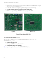
2.3 Open Source BDM Layout and Guidelines
The Open Source BDM is a two-sided PCB, roughly 3 in x 3 in larger, illustrated in Figure 8. The
gerber files are provided with the Open Source BDM in a later release. The gerber files can be
used to develop the design into another form factor if desired.
12
Open Source BDM PCB Hardware and MC68HC908JB16
Top View
Bottom View
Figure 8. Open Source PCB Layout
2.4 Getting Open Source BDM Components
A complete BOM is provided in Table 3, including all parts required for the Open Source BDM.
Each part is provided with order numbers from Digi-Key. Some of these components are
available as free samples. Free samples of Freescale’s HC908JB16 are available from
www.freescale.com.
Table 3 BOM
Generic Part
MC68HC908JB16DW
Description
Package
MCU
28-Pin SOIC
SN74LVC1T45DBVR
Level Shifter
6-Pin SOT-23
Crystal, 12 MHz
Citizen HC49US12.000MABJB-UB HC-49US
Component No.
U1
Digi-Key Part No.
Qty
MC68HC908JB16DW-ND
1
U2, U13
296-16843-1-ND
2
Y1
300-8492-ND
1
Capcitator, Electronic, 4.7µF
Panasonic ECE-A1VKG4R7
Radial Lead
C3, C7, C10, C18
P920-ND
4
Capcitator, Ceramic, 27pF
EPCOS B37979N1270J054
Radial Lead
C12, C13
495-1005-1-ND
2
Capcitator, 0.1µF
Kemet C320C104K5R5CA
Resistor, 10 1/4W 5%
Radial Lead
C4, C6, C17, C19
399-2054-ND
4
Axial Lead
R2, R3
10QBK-ND
2
Resistor, 470K 1/4W, 5%
Axial Lead
R18, R19
470KQBK-ND
2
Resistor, 10M 1/4W 5%
Axial Lead
R10
10MQBK-ND
1
Resistor, 470 1/4W 5%
Axial Lead
R11
470QBK-ND
1
Resistor, 47 1/4W 5%
Axial Lead
R22, R23
47QBK-ND
2
Resistor, 1.5K 1/4W 1%
Axial Lead
R20
1.5KXBK-ND
1
Resistor, 10K 1/4W 5%
Axial Lead
R21, R8*
10KQBK-ND
2
D3
LED, Green, Round, 5mm, T13/4
Fairchild HLMP3950A
Radial Lead
HLMP3950AFS-ND
1
USB Connector, Type B, PCB
Tyco 292304-1
Through Hole PCB S1
A31725-ND
1
Power Connector, 2-Pin Terminal Blk On-Shore Tech ED555/2
Through Hole PCB J1
ED1514-ND
1
Dual Row Header, 22-Pin
Molex/Waldom Electronics Corp.
Through Hole PCB JP2, J2
WM6822-ND
1
Single Row Header, 9-Pin
Molex/Waldom Electronics Corp.
Through Hole PCB JP1, JP3, JP4, JP5 WM6509-ND
1
13
Open Source BDM Interface Users Manual
3.0 JB16 USB/BDM Firmware
The HC908JB16 firmware was developed with the 3.1 special edition version of the CodeWarrior
Development Studio for HCS08. The project also works with the 5.0 special edition version. The
special edition provides a free solution for developing and debugging the Open Source BDM
project.
3.1 Firmware Description
The CodeWarrior Project Manger window for the HC908JB16 firmware project is illustrated in
Figure 9. The source files are organized so the firmware is delineated into logical blocks
including:
•
•
•
USB Block
Command Processing Block
BDM Block
Figure 9. Open Source BDM CodeWarrior Project Manager
14
JB16 USB/BDM Firmware
main.c/.h
Main program
Command.h
Provides command code use within the USB
messages
cmd_processing.c/.h
Decodes USB messages and commands into BDM
commands conform to the BDC. This source code
calls functions from bdm.c/.h.
bdm.c/.h
Provides tx/rx function to driver JB16 ports controlling
the targets BKGD pin. Time critical code uses
assembly code.
usb.c/.h
Provides function for USB communication using
endpoint 0 and endpoint 2
3.2 Programming Firmware into HC908JB16
Before a computer can recognize the Open Source BDM interface as a valid USB peripheral, the
Open Source BDM firmware requires downloading into the HC908JB16 microprocessor. The
following text describes programming of a blank HC908JB16 using the USB interface.
Programming the HC908JB16 using the USB interface uses the techniques described in
AN2399. A step-by-step guide is provided below.
1. Unzip the USB_ICP_demo.zip onto your computer. Included in these files are the
USB ICP drivers.
3.2.1 Configuring the Open Source BDM PCB
2. Close Jumpers JP3 and JP4. Also make sure R20 is not placed. This configures
the JB16 for USB In Circuit Programming.
3. Connect the Open Source BDM board to your computer through the USB cable.
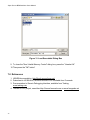
3.2.2 Installing USB ICP Drivers
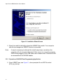
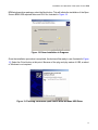
4. Once the Open Source BDM board to the computer, you should be prompted that
a new device has been detected and the Hardware Wizard should appear. Select
Install from a list or specific location, illustrated in Figure 10.
15
Open Source BDM Interface Users Manual
Figure 10. Installation Wizard Screen
5. Direct the install to the folder where the USBICP files reside. Your computer
should now recognize a USBICP device is connected.
Note:
It may be necessary to attempt this install many times, sometimes the
computer will not recognize the board. If this occurs try connecting reset to
GND before plugging in the USB cable, then releasie reset. Reset and GND
are accessible at the MON08 header.
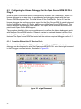
3.2.3 Operation of AN2399 Flash Programming Application
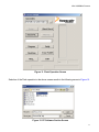
6. Open USBICP.exe, see Figure 11, when prompted for an IMP file select
jb16_icp_me.imp.
16
JB16 USB/BDM Firmware
Figure 11. Flash Operation Screen
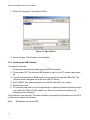
Selection of the Flash operation in the above screen results in the following screen in Figure 12.
Figure 12. PC Software Section Screen
17
Open Source BDM Interface Users Manual
7. Select File. Navigate to the desired s19 file.
Figure 13. Open Screen
8. Select Program. The firmware is now installed.
3.2.4 Updating the USB Firmware
To update the firmware:
1. Power down the board by removing the USB connection.
2. Close jumper JP5. This tells the USB firmware to jump to the ICP routines upon powerup.
3. Connect the Open Source BDM board to your computer through the USB cable. The
computer should recognize the board as a USB ICP device.
4. Open USBICP.exe. when prompted for an IMP file select jb16_icp_me.imp
5. Select Erase Flash.
6. If Problems persist with In Circuit Programming to update the firmware the best solution
is to replace the JB16 unit with a blank part. This will ensure that an update to the
firmware can be completed.
The Firmware is now removed. The steps outlined in programming the firmware into the JB16
can be used to update the firmware.
Note:
18
Remember to remove R20.
Open Source BDM PC Software
Note:
Firmware installed on Alpha Units (Boards Pre-Programmed with the firmware)
does not contain the ability to do this.
4.0 Open Source BDM PC Software
4.1 Overview
This section describes the Open Source BDM solution PC software components. These
components include:
•
•
•
Open Source BDM Generic Debug Instrument (GDI) DLL plug-in for the CodeWarrior
hiwave debugger
Open Source BDM interface DLL
USB driver (libusb.lib)
Figure 14 illustrates these software components and a simplification of their interfaces.
Figure 14. Open Source BDM Windows PC Software and Interfaces
4.2 Open Source BDM GDI DLL
The Open Source BDM GDI DLL plug-in for the CodeWarrior hiwave debugger is only available
as a binary file. No source code is provided. The GDI DLL for the CodeWarrior hiwave debugger
is created partially based on information not available in the public domain. The license attached
to these files does not allow disclosure of the file’s source code.
The Open Source BDM takes advantage of the CodeWarrior version 5.0 Degugger’s Generic
Debug Instrument (GDI) protocol interface. Tasking Incoporated provides more detailed
information about the GDI Open Interface Specification (see http://www.tasking.com/resources/
technologies/debuggers/gdikdi/); the Tasking specification is publicly available.
19
Open Source BDM Interface Users Manual
4.3 Open Source BDM DLL and LIBUSB
The Open Source BDM DLL provides an interface between the Open Source BDM GDI DLL and
the Open Source BDM firmware. This section describes the API of the Open Source BDM DLL
including a Windows Open Source USB drivers library, LIBUSB. The source code for the Open
Source BDM DLL is available.
4.3.1 Command.h
Command.h provides command code use within the USB messages. This file matches the
command.h file in the Open Source BDM firmware.
4.3.2 OpenSourceBDM.h/.c
OpenSourceBDM.c/.h provides the API functions for the Open Source BDM DLL. These
functions are called by the Open Source BDM GDI DLL. The functions in turn call functions of
LIBUSB. These functions are encapsulated into the OpenSourceBDM.dll. OpenSourceBDM.dll
is a part of the Windows USB install package for the Open Source BDM. The Open Source BDM
DLL functions are listed and briefly described below.
unsigned char OpenSourceBDM_OpenSourceBDM_dll_version(void)
Returns version of the DLL in BCD format (major in upper nibble and minor in lower nibble).
unsigned char OpenSourceBDM_init(void)
Initializes the USB interface, returning the number of Open Source BDM devices found attached
to the computer. This function should be called before a device can be opened.
unsigned char OpenSourceBDM_open(unsigned char device_no)
Opens communication with device number device_no. First device has number 0. Returns 0 on
success and non-zero on failure. A device must be open before any communication with the
device can take place.
void OpenSourceBDM_close(void)
Closes communication with currently opened device.
unsigned int OpenSourceBDM_get_version(void)
Returns version of HW (MSB) and SW (LSB) of the Open Source BDM interface in BCD format.
20
Open Source BDM PC Software
unsigned char OpenSourceBDM_get_last_sts(void)
Returns status of the last executed command: 0 on success and non-zero on failure.
unsigned char OpenSourceBDM_set_target_type(target_type_e target_type)
This function sets target MCU type. target_type can be either HC12 or HCS08. Returns 0 on
success and non-zero on failure.
unsigned char OpenSourceBDM_target_sync(void)
Measures BDM frequency of the target using the SYNC BDM feature and connects to the target.
Returns 0 on success and non-zero on failure (no device connected or the SYNC feature not
supported). If this function succeeds, there is no need to set the BDM communication speed as
it is measured automatically.
unsigned char OpenSourceBDM_target_reset(target_mode_e target_mode)
Resets the target MCU to normal or special mode. target_mode can be either SPECIAL_MODE
or NORMAL_MODE. Returns 0 on success and non-zero on failure (reset pin stuck to ground,
etc.).
unsigned char OpenSourceBDM_bdm_sts(bdm_status_t *bdm_status)
bdm_status is a pointer to allocated structure the function fills with current state of BDM
communication. Returns 0 on success and non-zero on failure.
The structure has the following format:
typedef struct {
ackn_state_e ackn_state;
reset_state_e reset_state;
connection_state_e connection_state; } bdm_status_t;
ackn_state can be either ACKN (target supports ACKN BDM feature) or WAIT (target does not
support ACKN BDM feature).
reset_state can be either RESET_INACTIVE (no reset activity detected) or RESET_DETECTED
(target was reset since the last call). reset_state defaults to RESET_INACTIVE after each call.
connection_state can be NO_CONNECTION (no target MCU detected), SYNC (target supports
the SYNC BDM feature) or MANUAL_SETUP (BDM speed was set-up by calling
OpenSourceBDM_set_speed - see below).
21
Open Source BDM Interface Users Manual
unsigned char OpenSourceBDM_target_go(void)
Starts target code execution from current PC address. Returns 0 on success and non-zero on
failure.
unsigned char OpenSourceBDM_target_step(void)
Steps over a single target instruction. Returns 0 on success and non-zero on failure.
unsigned char OpenSourceBDM_target_halt(void)
Brings the target into active background mode, i.e., debug mode with user code execution halted.
Returns 0 on success and non-zero on failure.
unsigned char OpenSourceBDM_set_speed(float crystal_frequency)
Sets the BDM communication speed. crystal_frequency is crystal, or external source, frequency
in MHz. Returns 0 on success and non-zero on failure. It is essential to provide frequency
accurate at least to two decimal places in MHz.
float OpenSourceBDM_get_speed(void)
Returns crystal (or external source) frequency of the target in MHz.
unsigned char OpenSourceBDM_read_byte(unsigned int address)
Reads one byte from memory at the supplied address.
void OpenSourceBDM_write_byte(unsigned int address, unsigned char data)
Writes one byte to memory at the supplied address.
void OpenSourceBDM_read_block(unsigned int address, unsigned int count, unsigned
char *data)
Reads count bytes from address address. The data is written to a user supplied buffer.
void OpenSourceBDM_write_block(unsigned int address, unsigned int count, unsigned
char *data)
Writes count bytes to address address. The data is take from a user supplied buffer.
22
Open Source BDM PC Software
unsigned char OpenSourceBDM_read_regs(registers_t *registers)
Reads contents of target registers. Returns 0 on success and non-zero on failure. The register
values are filed into user-allocated structure of the following format:
typedef union {
struct {
unsigned int pc;
unsigned int sp;
unsigned int ix;
unsigned int iy;
unsigned int d;
unsigned int ccr;
} hc12;
struct {
unsigned
unsigned
unsigned
unsigned
unsigned
} hcs08;
int pc;
int sp;
int hx;
int a;
int ccr;
} registers_t;
void OpenSourceBDM_write_reg_pc(unsigned int value)
Writes a new value into the PC target register.
void OpenSourceBDM_write_reg_sp(unsigned int value)
Writes a new value into the SP target register.
void OpenSourceBDM_write_reg_x(unsigned int value)
Writes a new value into the H:X (S08) target register.
void OpenSourceBDM_write_reg_d(unsigned int value)
Writes a new value into the A (S08) target register.
void OpenSourceBDM_write_reg_ccr(unsigned int value)
Writes a new value into the CCR target register.
LIBUSB
The LIBUSB is Open Source software available under combination of GNU general and lesser
general public licenses. The Open Source BDM DLL functions utilize the following LIBUSB API
functions:
23
Open Source BDM Interface Users Manual
•
•
•
•
•
•
•
•
•
usb_find_buses
usb_find_devices
usb_close
usb_open
usb_get_version
usb_init
usb_control_msg
usb_bulk_write
usb_bulk_read
5.0 Erasing and Programming Algorithms
Other aspects of the development tool system are the erasing and programming algorithms.
Before a new program can be uploaded into the target system, the target must be erased before
it can be programmed. In order to both erase and program the target, a program must be loaded
into RAM first. Both are separate erase and program algorithms. These programs provide a
means to write to, and erase flash.
Every part family and every derivative has a distinct erasing and programming algorithm file.
These files are not included in this version of the Open Source BDM, but some erasing and
programming algorithm file from within the CodeWarrior installation can be used. Erasing and
programming algorithm are not directly supported by CodeWarrior, consquently they are not
guaranteed. Figure 15 illustrates the location of these files within the CodeWarrior installation in
the fpp directory. It is not necessary to access the files directly, the Open Source BDM is
configured to access the files during target erase and programming operations.
Figure 15. Path to FPP
24
Installation and Operation of the Open Source BDM
6.0 Installation and Operation of the Open Source BDM
6.1 Configuration of the Open Source BDM PCB
This section assumes the Open Source BDM firmware is programmed on to the JB16.
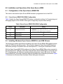
6.1.1 Open Source BDM PCB HCS08 Configuration
Table 4 details the Open Source BDM PCB jumper configuration settings for Programming and
debugging targets for the HCS08. Other types of target may required other settings.
Table 4 Open Source BDM PCB HCS08 Configuration
Jumper
Description
Setting
•
JP1
Target Power Selection
•
Short 1-2: Power target externally via J1 or target is selfpowered
Short 2-3: Power target using 5V USB power
JP3
Flash Program
Off
JP4
Flash Program
Off
JP5
Flash Erase
Off
6.2 Installing Windows Open Source BDM DLL and USB Drivers
The following procedure specifies the installing of the Open Source BDM USB hardware drivers
under the Windows operating system. This procedure assumes Open Source BDM windows
USB driver package is unpacked onto the development PC, running the CodeWarrior Studio.
With the Open Source BDM PCB configured, the Open Source BDM PCB can be connected to
the development PC USB port. When the configured Open Source BDM PCB is connected to the
PC for the first time, the Windows operating system recognizes a new USB device, the Open
Source BDM PCB. This initial connection starts the Windows driver installation procedure. Figure
16 illustrates the Windows New Hardware Wizard dialog box that opens.
25
Open Source BDM Interface Users Manual
Figure 16. Found New Hardware Dialog Box
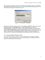
For this installation, select the option to Install from a Specific Location, then click Next. When
the Next button is selected, the Specify Location of the Drivers dialog box opens, illustrated in
Figure 17.
Figure 17. Specifying Location of Drivers Dialog Box
In the Specify Location of the Drivers dialog box, point the Hardware Wizard to the unzipped
Open Source BDM windows driver package, using the Browse button. Once the Windows
Specify Location of the Drivers dialog box is configured with the correct path to the Open Source
26
Installation and Operation of the Open Source BDM
BDM windows driver package, select the Next button. This will initiate the installation of the Open
Source BDM USB required driver and DLL file, ilustrated in Figure 18.
Figure 18. Driver Installation in Progress
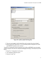
Once the installation procedure is completed, the device will be ready to use, illustrated in Figure
19. Select the Finish button at this point. Because of the plug and play nature of USB, a reboot
of Windows is not required.
Figure 19. Finishing Installation Open Source BDM Windows USB Driver
27
Open Source BDM Interface Users Manual
6.3 Configuring the Hiwave Debugger for the Open Source BDM GDI DLL
Plug-in
Once the Open Source BDM device is recognized by Windows, the CodeWarrior version 5.0
hiwave debugger is one step closer to programming and debugging targets with the Open
Source BDM development tool. The initial release of the CodeWarrior version 5.0 and the
hiwave debugger does not have obvious support for the Open Source BDM. A patch is planned
for the CodeWarrior version 5.0 Studio, adding more visible Open Source BDM support. This
section describes configuration of the hiwave for the Open Source BDM with and without the
patch to add Open Source BDM support.
The procedure detailed in this section explains how to configure the hiwave debugger to work
with the Open Source BDM interface. Please be certain to download the latest version of the
tools from Metrowerks. The debugger interface of older versions do not support the required
features. The Open Source BDM was tested with the minimum required debugger version 6.1.
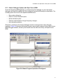
6.3.1 Operation Without the CW Service Patch
Even without the Open Source BDM patch for the CodeWarrior HCS08 Studio, the hiwave
debugger can be configured to select the OpenSourceBDM GDI DLL using the set gdi command
in the Debugger command window, illustrated in Figure 20.
Figure 20. set gdi Command
28
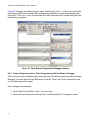
Installation and Operation of the Open Source BDM
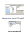
When the set gdi command is executed, the GDI Setup DLL dialog box opens. To use the Open
Source BDM, select the Browse button to choose the required OpenSourceBDM_gdi.dll file. The
GDI Setup DLL dialog box is illustrated in Figure 21.
Figure 21. GDI Setup DLL Dialog Box
Sometimes the "set gdi" command does not force a change of the GDI DLL setup (note the active
GDI setup is shown in the debugger menu, i.e. Open Source BDM menu option vs.
MultilinkCyclonePro vs. MONITOR-HCS08 vs. Softec-HCS08). This issue occurs when the
Softec-HCS08 debugger target is selected in the Code Warrior IDE. The solutions is to NOT to
select the Softec-HCS08 debugger target (select P&E instead). When a service patch for Code
Warrior to add support for the Open Source BDM is avaiable, the set gdi command is not
necessary since the Open Source BDM target will be selectable from the Code Warrior IDE.
6.3.2 Operation With the CW Service Patch
In this case, when a project is created, it can be created based on the Open Source BDM
connection. Figure 22 illustrates the Connection Option dialog box. CodeWarrior provides a
Open Source BDM option in this dialog box.
29
Open Source BDM Interface Users Manual
Figure 22. New Project Debugger Interface Connections Dialog Box
Alternatively, if the project was built with other connection using the New Project Debugger
Interface Connections dialog box, it can be easily changed in the CodeWarrior IDE project
manager, illustrated Figure 23. Also, the set gdi command can still be used in the hiwave
debugger.
Figure 23. Project Manager Connection Options
30
Installation and Operation of the Open Source BDM
6.3.3 Hiwave Debugger Options with Open Source BDM
Once the OpenSourceBDM GDI DLL is configured and the debugger is open, the hiwave
debugger and OpenSourceBDM GDI DLL provide full featured functionality provided below. The
folowing options are found in the OpenSourceBDM menu:
•
•
•
•
•
Show status dialog box
Reset to normal command option
Select derivative option
Detection and indication of target frequency changes
Auto derivative selection
Otherwise, operation for the hiwave debugger remains unchanged from other debugger
interfaces. Figure 24 illustrates the hiwave program opened and configured for the Open Source
BDM debugger interface, shown by the hiwave menu bar with menu entry call Open Source
BDM.
Figure 24. Hiwave Program Opened and Configured
31
Open Source BDM Interface Users Manual
6.4 Programming and Erasing Flash with Open Source BDM
Using the Open Source BDM is no different than using other debugger development tools. The
basics steps for configuration and operation of the Open Source BDM for programming and
debugging a target system are:
1. Build or otherwise obtain the Open Source BDM PCB
2. Configure the debugger hardware for the Open Source BDM PCB. See "Open Source
BDM PCB HCS08 Configuration," Section 6.1.1
3. Connect the debugger hardware as shown in Figure1
4. If necessary, install the debugger hardware windows drivers. See "Installing Windows
Open Source BDM DDL and USB Drivers," Section 6.1
5. Develop a user application and select the desired debugger interface in the CodeWarrior
IDE. See "Configuring the Hiwave Debugger for the Open Source BDM GDI DLL Plug-in"
Section 6.3
6. Execute the command to open the hiwave debugger, making certain the correct
debugger interface is selected. Open Source BDM. See step five above.
7. The hiwave debugger opens and erases, then programs the target system. A manually
selected file can also be used to upload into the target system. See "Step-by-step
Instructions: Flash Programming with the Hiwave Debugger," Section 6.4.2
8. Debug the code using the hiwave debugger. Users have access to all debugger
functions including breakpoints, trace, program halt/go, program step/step-over/stepinto, and many other debugger command options.
Figure 25 illustrates the cable connections between the PC, the Open Source BDM, and the
user target. Detailed information is provided below about using the CodeWarrior IDE.
32
Installation and Operation of the Open Source BDM
Figure 25. Cable Connections Between the PC and the Open Source BDM
6.4.1 Opening the Hiwave Debugger
Once the main code is added, the project code can be downloaded into the target MCU flash
memory. Figure 26 shows pressing the debug icon in the CodeWarrior IDE’s program manger
window will initiate the programming of the target MCU flash memory. This icon executes a
command to open the hiwave program.
Figure 26. Code Warrior IDE Debug Icon
33
Open Source BDM Interface Users Manual
Figure 27 illustrates the hiwave program again. Selecting the Load... or Flash command in the
Open Source BDM menu initiates flash programming algorithms to erase and reprogram the
target MCU. The Load... menu command will first allow a selected file to upload during the flash
programming operation.
Figure 27. Code Warrior Programmer/Debugger Interface
6.4.2 Step-by-Step Instructions: Flash Programming with the Hiwave Debugger
This sections provides detailed step-by-step instructions for flash programming with the Hiware
debugger. From the Open Source BDM menu, both the "Flash" and "Load" command can be
used to flash program the target.
6.4.2.1 Using the Load Command:
1. Select Open Source BDM > Load... from the menu
2. When the load command is executed, the "Load Executable File" dialog box opens.
34
Installation and Operation of the Open Source BDM
Figure 28. Load Executable File Dialog Box
3. The user must navigate to the file that will be used to program the part and select it
4. Before pressing the "Open Button," the "Automatically erase and program into FLASH
and EEPROM" checkbox must be checked
To make the "Automatically erase and program into FLASH and EEPROM" option the default
setting for a project, the user must configure the debugger accordingly. These steps are provide
below:
1. Select File > Configuration from the menu
2. The "Preference" dialog box opens
3. Select the "Load" Tab
35
Open Source BDM Interface Users Manual
Figure 29. Preferences Dialog Box
4.
5.
6.
7.
Check the "Automatically erase and program into FLASH and EEPROM" checkbox
Close "Preference" dialog box by pressing the "OK" button
Select File > Save Configuration from the menu
Next time, auto erase and flash functions will be performed by default
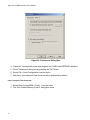
6.4.2.2 Using the Flash Command:
1. Select Open Source BDM > Flash... from the menu
2. The "Non Volatile Memory Control" dialog box opens
36
Installation and Operation of the Open Source BDM
Figure 30. Non Volatile Memory Control Dialog Box
3.
4.
5.
6.
7.
8.
Press the "Select All" button
Press the "Erase" button
Press the "Load..." button
When the load button is pressed, the "Load Executable File" dialog box opens.
The user must navigate to the file that will be used to program the part and select it
Pressing the "Open" button programs the part
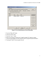
37
Open Source BDM Interface Users Manual
Figure 31. Load Executable Dialog Box
9. To close the "Non Volatile Memory Control" dialog box, press the "Unselect All"
10. Then press the "OK" button"
7.0 References
1. LIBUSB documentation, http://libusb.sourceforge.net/
2. Data sheet to HC908JB16, MC68HC908JB16.PDF available from Freescale
3. Documentation to Generic Debugging Interface, available from Tasking,
www.tasking.com
4. TBDML HCS12 project, see either http://forums.freescale.com or www.freegeeks.net
38