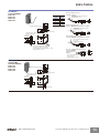
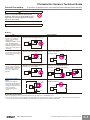
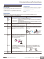
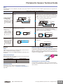
1
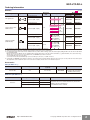
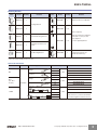
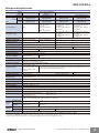
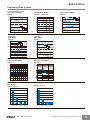
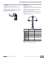
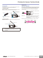
Laser Photoelectric Sensor with Built-in Amplifier E3Z-LT/LR/LL The Most Compact Laser Sensor The Most Reliable E3Z ■ Excellent quality of E3Z such as the maximum ambient operating temperate of 55°C, IP67 degree of protection is inherited. ■ Safe and reliable class 1 (JIS/IEC) laser used ■ Excellent detection performance supporting long distance and low hysteresis ■ Complete Compliance with RoHS ■ Spot diameters can be customized. Increasing the spot diameter makes optical axis adjustment easier. Be sure to read Safety Precautions on page 9. Applications Count bottles. Detect the sides of large tiles. Greatly Enhanced Beam Visibility for Easier Optical Axis Adjustment of Sensors Reliable Detection of Small Objects and Narrow Gaps with the Small Spot Detect chip components on tape. Detect protruding straws. Long-distance Sensing at 300 mm (White Paper) A Low Black/White Error for Applications with Mixed Colors Optical Customization for E3Z Lasers That Fit the Application! The E3Z laser system has an original modular structure. Spot diameters can be customized, as shown in the examples below. For example, when a through-beam model is used at far range, the optical axis can be easily adjusted by widening the spot, and minute objects can be easily detected by minimizing the spot at close range. These applications improve product value. Advanced Optical Technology of the E3Z Laser Holder Laser Modular Conceptual Diagram Laser beam directional deviation can be suppressed and spot diameters can be freely customized. This is achieved through high-precision alignment technology based on LD and emitter lens modularization. Laser beam LD (semiconductor laser) Emitter lens The lens position can be adjusted inline. (Patent pending.) By precisely adjusting the emitter lens in the vertical, horizontal, and depth directions, alignment can be achieved with minimal directional deviation (to ±1 degree). http://www.ia.omron.com/ (c)Copyright OMRON Corporation 2007 All Rights Reserved. 1 E3Z-LT/LR/LL Ordering Information Sensors Red light Sensing method Appearance Connection method Response time Pre-wired (2 m)*3 Through-beam Model NPN output PNP output E3Z-LT61 E3Z-LT81 Sensing distance *4 Connector (M8, 4 pins) 60 m E3Z-LT66 E3Z-LT86 Pre-wired (2 m)*3 *2 E3Z-LR61 E3Z-LR81 E3Z-LR66 E3Z-LR86 E3Z-LL61 E3Z-LL81 E3Z-LL66 E3Z-LL86 E3Z-LL63 E3Z-LL83 E3Z-LL68 E3Z-LL88 15 m (300 mm) (Using E39-R1) Retro-reflective with MSR function *1 Connector (M8, 4 pins) 7m 1 ms (Using E39-R12) (200 mm) 7m (Using E39-R6) Pre-wired (2 m)*3 (200 mm) 20 to 40 mm (Min. distance set) Connector (M8, 4 pins) 20 to 300 mm (Max. distance set) Distance-settable (BGS Models) Pre-wired (2 m)*3 Connector (M8, 4 pins) 25 to 40 mm 0.5 ms (Min. distance set) 25 to 300 mm (Max. distance set) *1. The Reflector is sold separately. Select the Reflector model most suited to the application. *2. Values in parentheses indicate the minimum required distance between the Sensor and Reflector. *3. Pre-wired Models with a 0.5-m cable are also available for these products. When ordering, specify the cable length by adding “0.5M” to the end of the model number (e.g., E3Z-LT61 0.5M). M12 Pre-wired Connector Models are also available. When ordering, add “-M1J” to the end of the model number (e.g., E3Z-LT61-M1J). The cable is 0.3 m long. The following connection forms are also available. Ask your OMRON representative for details. • Pre-wired Models with 1-m or 5-m cables • Pre-wired Connector Models with M8 4-pin connectors, M8 3-pin connectors, or e-CON connectors. *4. Consult with your OMRON representative if a distance of more than 10 m is required. Models with large custom-size spots can be produced. These make optical axis adjustment easier and allow the beam to be received more stably by the Receiver even if vibration is present. Accessories Slits (for E3Z-LT@@) Slit width Sensing distance Minimum detectable object (typical) Model Contents 0.5 mm dia. 3m 0.1 mm dia. E39-S65A One set (contains Slits for both the Emitter and Receiver) Reflectors (for E3Z-LR@@) Name Reflector Sensing distance (typical) Model 15 m (300 mm) E39-R1 7 m (200 mm) E39-R12 7 m (200 mm) E39-R6 http://www.ia.omron.com/ Remarks • Retro-reflective models are not provided with Reflectors. • Separate the Sensor and the Reflector by at least the distance given in parentheses. • The MSR function is enabled. (c)Copyright OMRON Corporation 2007 All Rights Reserved. 2 E3Z-LT/LR/LL Mounting Brackets Appearance Model Quantity E39-L153 1 Appearance Remarks Model Quantity Remarks E39-L98 1 Metal Protective Cover Bracket * E39-L150 1 set Mounting Brackets E39-L104 1 (Sensor adjuster) E39-L43 1 Easily mounted to the aluminum frame rails of conveyors and easily adjusted. Horizontal Mounting Bracket * E39-L142 1 Horizontal Protective Cover Bracket * E39-L44 1 Rear Mounting Bracket E39-L151 1 set For left to right adjustment E39-L144 1 Compact Protective Cover Bracket (For E3Z only) * Note: When using Through-beam models, order one bracket for the Receiver and one for the Emitter. * Cannot be used for Standard Connector models. Sensor I/O Connectors Size Cable Appearance Cable type 2m Straight 5m M8 2m L-shaped M12 (For -M1J models) Straight L-shaped 432 1 Connector on One End XS3F-M421-405-A XS3F-M422-402-A XS3F-M422-405-A 2m XS2F-D421-DC0-A 3-wire XS2F-D421-GC0-A 2m XS2F-D422-DC0-A 5m XS2F-D422-GC0-A 2m E39-ECON2M 0.5 to 1 m 1.1 to 1.5 m 12 3 4 http://www.ia.omron.com/ 4-wire 5m Connectors of Both Ends 432 1 e-CON XS3F-M421-402-A 5m 5m Standard Model 1.6 to 2 m E39-ECON5M 4-wire E39-ECONW@M Replace the box (@) in the model number by the cable length in increments of 0.1 m. (c)Copyright OMRON Corporation 2007 All Rights Reserved. 3 E3Z-LT/LR/LL Ratings and Specifications Sensing method Retro-reflective with MSR function Through-beam Response Model Item Distance-settable (BGS models) Standard response High-speed response NPN output E3Z-LT61/-LT66 E3Z-LR61/-LR66 E3Z-LL61/-LL66 E3Z-LL63/-LL68 PNP output E3Z-LT81/-LT86 E3Z-LR81/-LR86 E3Z-LL81/-LL86 E3Z-LL83/-LL88 Sensing distance 0.3 to 15 m (when using E39-R1) 0.2 to 7 m (when using E39-R12) 0.2 to 7 m (when using E39-R6) 60 m * Set distance range --- Spot diameter (typical) 5-mm dia. at 3 m Standard sensing object Opaque: 12-mm dia. min. Minimum detectable object (typical) 6-mm-dia. opaque object at 3 m White paper (100 100 mm): 20 to 300 mm Black paper (100 100 mm): 20 to 160 mm White paper (100 100 mm): 25 to 300 mm Black paper (100 100 mm): 25 to 100 mm White paper (100 100 mm): 40 to 300 mm Black paper (100 100 mm): 40 to 160 mm White paper (100 100 mm): 40 to 300 mm Black paper (100 100 mm): 40 to 100 mm 0.5-mm dia. at 300 mm Opaque: 75-mm dia. min. --0.2-mm-dia. stainless-steel pin gauge at 300 mm Differential travel --- 5% max. of set distance Black/white error --- 5% at 160 mm 5% at 100 mm Directional angle Receiver: 3 to 15 Light source (wavelength) Red LD (655 nm), JIS CLass 1, IEC Class 1, FDA Class II Power supply voltage 12 to 24 VDC10%, ripple (p-p): 10% max. Current consumption 35 mA (Emitter 15 mA, Receiver 20 mA) Control output Load power supply voltage: 26.4 VDC max., Load current: 100 mA max., Open collector output Residual output voltage Load current of less than 10 mA: 1 V max. Load current of 10 to 100 mA: 2 V max. Output mode switching Switch to change between light-ON and dark-ON Protection circuits Reversed power supply polarity protection, Output short-circuit protection, and Reversed output polarity protection Response time Operate or reset: 1 ms max. Sensitivity adjustment One-turn adjuster Ambient illumination (Receiver side) Incandescent lamp: 3,000 lx max. Sunlight: 10,000 lx max. Ambient temperature range Operating: 10 to 55C, Storage: 25 to 70C (with no icing or condensation) Ambient humidity range Operating: 35% to 85%, Storage: 35% to 95% (with no icing or condensation) Insulation resistance 20 M: min. at 500 VDC Dielectric strength 1,000 VAC, 50/60 Hz for 1 min Vibration resistance Destruction: 10 to 55 Hz, 1.5-mm double amplitude for 2 hours each in X, Y, and Z directions Shock resistance Destruction: 500 m/s2 3 times each in X, Y, and Z directions Degree of protection IP67 (IEC 60529) Connection method Pre-wired cable (standard length: 2 m): Standard M8 Connector: Indicator Operation indicator (orange) Stability indicator (green) Emitter for Through-bream Models has power indicator (orange) only. Weight (packed state) Material --- 30 mA max. Reversed power supply polarity protection, Output short-circuit protection, Mutual interference prevention, and Reversed output polarity protection Operate or reset: 0.5 ms max. Five-turn endless adjuster Pre-wired cable (2 m) Approx. 120 g Approx. 65 g Standard Connector Approx. 30 g Approx. 20 g Case PBT (polybutylene terephthalate) Lens Accessories Modified polyarylate resin E3Z-L@@1/-L@@3 E3Z-L@@6/-L@@8 Methacrylic resin Modified polyarylate resin Instruction manual (Neither Reflectors nor Mounting Brackets are provided with any of the above models.) Note: An emission stop function can be added to Through-beam Models as a custom function. Ask your OMRON representative for details. * Consult with your OMRON representative if a distance of more than 10 m is required. Models with large custom-size spots can be produced. These make optical axis adjustment easier and allow the beam to be received more stably by the Receiver even if vibration is present. http://www.ia.omron.com/ (c)Copyright OMRON Corporation 2007 All Rights Reserved. 4 E3Z-LT/LR/LL Engineering Data (Typical) Through-beam Models E3Z-LT@@ + E39-65A 150 100 Retro-reflective Models E3Z-LR@@ 20 Distance Y (mm) Distance (mm) Distance Y (mm) Parallel Operating Range Through-beam Models E3Z-LT@@ 15 10 50 5 0 20 40 60 0 80 2 4 6 8 10 −5 −50 60 E39-R1 Y 40 20 0 −10 −20 Y Sensing object: 100 × 100 mm white paper 1.50 X 1.00 0.50 0.00 0 50 100 150 200 30 Distance X (m) 3 2 Y Sensing object: 100 × 100 mm white paper 1 X 0 350 250 −0.50 25 Operating Range at a Set Distance of 40 mm BGS Models E3Z-LL@@ Operating range Y (mm) Operating range Y (mm) 2.00 20 −60 Distance (m) Distance X (m) 2.50 15 −40 −15 Operating Range at a Set Distance of 300 mm BGS Models E3Z-LL@@ 10 E39-R12 X −150 5 −20 Y −100 X E39-R6 10 20 30 40 50 60 300 −1 −1.00 −1.50 −2 −2.00 −2.50 −3 Distance X (mm) Distance X (mm) 10000 Retro-reflective Models E3Z-LR@@ Excess gain ratio (multiple) Excess gain ratio (multiple) Excess Gain vs. Set Distance Through-beam Models E3Z-LT@@ 1000 100 E39-R1 10 E39-R12 1 E39-R6 100 0 10 20 30 40 50 60 70 0.1 80 0 10 20 30 Distance (m) 350 300 E3Z-LL@3/-LL@8 Sensing distance (mm) Sensing distance (mm) Close Range Characteristics BGS Models E3Z-LL@1/-LL@6 Distance (m) 300 mm 250 200 350 300 300 mm 250 200 160 mm 150 150 100 100 40 mm 50 0 10 mm White paper Setting: 300 mm 12 mm Black paper Setting: 160 mm 0 mm White paper Setting: 40 mm 40 mm 9 mm Black paper Setting: 40 mm http://www.ia.omron.com/ 100 mm 40 mm 50 10 mm 0 White paper Setting: 300 mm 21 mm Black paper Setting: 100 mm White paper Setting: 40 mm 0 mm 40 mm 9 mm Black paper Setting: 40 mm (c)Copyright OMRON Corporation 2007 All Rights Reserved. 5 E3Z-LT/LR/LL 50 Sensing distance (mm) 50 40 30 40 30 20 20 10 10 E3Z-LL@1/-LL@6 White Paper with a Set Distance of 300 mm Sensing distance (mm) Sensing distance (mm) Sensing Distance vs. Sensing Object Material BGS Models E3Z-LL@1/-LL@6 E3Z-LL@3/-LL@8 White Paper with a Set Distance of 40 mm White Paper with a Set Distance of 40 mm 350 300 250 200 150 100 50 0 White Veneer Card- Black Black SUS paper board paper rubber 0 0 Mirror surface White Veneer Card- Black Black SUS paper board paper rubber Material Material BGS Models (Same for All Models) E3Z-LT@@, E3Z-LR@@ E3Z-LL@@ 100 100 80 Spot diameter (mm) 120 Mirror surface Material Emission Spot Diameter vs. Distance Through-beam and Retro-reflective Models (Same for All Models) Spot diameter (mm) Sensing distance (mm) E3Z-LL@3/-LL@8 White Paper with a Set Distance of 100 mm White Veneer Card- Black Black SUS paper board paper rubber Mirror surface b 90 80 a 70 Spot shape Dimension a 60 60 1.4 1.2 Dimension a 1.0 0.8 50 30 b 0.4 20 20 Dimension b 0.6 40 40 Dimension b 0.2 a 10 0 0 White Veneer Card- Black Black SUS paper board paper rubber 0 0 Mirror surface Spot shape 10 20 30 40 50 60 Set distance (m) 0 100 200 300 400 500 600 Set distance (mm) Material E3Z-LL@3 (LL@8) Hysteresis (%) Hysteresis (%) Hysteresis vs. Distance BGS Models E3Z-LL@1 (LL@6) 2.50 2.00 Black paper 1.50 2.50 2.00 Black paper 1.50 1.00 1.00 White paper White paper 0.50 0.50 0.00 0.00 0 100 200 300 400 0 100 200 300 Set distance (mm) 20 Distance setting: 300 mm Sensing object: White paper 100 × 100 mm 15 10 5 0 (Upwards and Downwards) Inclination angle −5 −10 Inclination Characteristics (Horizontal) BGS Models E3Z-LL@@ Sensing distance variation (%) Sensing distance variation (%) Inclination Characteristics (Vertical) BGS Models E3Z-LL@@ 20 15 5 0 −5 −10 Sensing object −20 −40 −30 Center line −20 −10 −15 −θ 0 10 20 30 40 Inclination angle θ (°) http://www.ia.omron.com/ Distance setting: 300 mm Sensing object: White paper 100 × 100 mm 10 +θ −15 400 Set distance (mm) (Left and Right) Inclination angle +θ −θ Sensing Center object line −20 −40 −30 −20 −10 0 10 20 30 40 Inclination angle θ (°) (c)Copyright OMRON Corporation 2007 All Rights Reserved. 6 E3Z-LT/LR/LL I/O Circuit Diagrams NPN Output Model E3Z-LT61 E3Z-LT66 E3Z-LR61 E3Z-LR66 Operation mode Timing charts Light-ON Light incident Light interrupted Operation indicator ON (orange) OFF ON Output transistor OFF Load Operate (e.g., relay) Reset (Between brown and black leads) Dark-ON Operation selector Light incident Light interrupted Operation indicator ON (orange) OFF ON Output transistor OFF Load Operate (e.g., relay) Reset (Between brown and black leads) Through-beam Receivers, Retro-reflective Models E3Z-LL61 E3Z-LL66 E3Z-LL63 E3Z-LL68 D side (DARK ON) (Control output) Black ZD Blue 3 M8 4-pin Connector Pin Arrangement 1 2 2 e-CON Connector Pin Arrangement M8 3-pin Connector Pin Arrangement 1 Press fit 2 4 4 1 4 3 1 3 3 4 Pin 2 is not used. M12 Connector Pin Arrangement 2 2 12 to 24 VDC M8 3-pin Connector Pin Arrangement M8 4-pin Connector Pin Arrangement e-CON Connector Pin Arrangement 1 Press fit 2 4 4 1 4 1 3 3 3 Blue 3 4 Pins 2 and 4 are not used. FAR Operation ON indicator (orange) OFF ON Output transistor OFF Load Operate (e.g., relay) Reset (Between brown and black leads) Load (Relay) 100 mA max. 4 3 12 to 24 VDC Brown D side (DARK ON) Operation mode Timing charts Operation selector Light-ON Light incident Light interrupted Operation indicator ON (orange) OFF ON Output transistor OFF Load Operate (e.g., relay) Reset (Between blue and black leads) 1 Operation indicator L side (LIGHT ON) NEAR FAR Operation indicator ON (orange) OFF Output ON transistor OFF Load Operate (e.g., relay) Reset (Between brown and black leads) Dark-ON M12 Connector Pin Arrangement 1 NEAR Light-ON (Orange) 0V Brown 3 1 Stability indicator (Green) Photoelectric Sensor Main Circuit 1 Photo-electric Sensor Main Circuit 12 to 24 VDC Brown Operation indicator L side (LIGHT ON) Through-beam Emitter Power indicator (orange) Output circuit Stability indicator (Green) (Orange) (Control output) Photoelectric Sensor Main Circuit M12 Connector Pin Arrangement 4 2 Blue 3 0V e-CON Connector Pin Arrangement M8 3-pin Connector Pin Arrangement 4 1 4 Load (Relay) Black ZD M8 4-pin Connector Pin Arrangement 1 2 100 mA max. 1 Press fit 2 4 3 1 3 3 3 4 Pin 2 is not used. PNP Output Model E3Z-LT81 E3Z-LT86 E3Z-LR81 E3Z-LR86 Dark-ON Light incident Light interrupted Operation indicator ON (orange) OFF ON Output transistor OFF Load Operate (e.g., relay) Reset (Between blue and black leads) Output circuit Through-beam Receivers, Retro-reflective Models 12 to 24 VDC Brown 1 Operation indicator L side (LIGHT ON) Stability indicator (Green) (Orange) ZD Black Photoelectric Sensor Main Circuit M12 Connector Pin Arrangement 2 2 Load (Relay) 0V Blue M8 3-pin Connector e-CON Connector Pin Arrangement Pin Arrangement 4 4 1 4 100 mA max. 3 M8 4-pin Connector Pin Arrangement 1 D side (DARK ON) 4 (Control output) 1 3 1 2 3 3 Pin 2 is not used. Press fit 3 4 Through-beam Emitter Brown Power indicator (orange) M12 Connector Pin Arrangement 1 1 Photo-electric Sensor Main Circuit 12 to 24 VDC 2 2 1 4 E3Z-LL81 E3Z-LL86 E3Z-LL83 E3Z-LL88 1 Press fit 2 4 4 1 3 3 3 NEAR FAR Operation indicator ON (orange) OFF Output ON transistor OFF Load Operate (e.g., relay) Reset (Between blue and black leads) NEAR Dark-ON e-CON Connector M8 3-pin Connector Pin Arrangement Pin Arrangement 3 4 Blue 3 Light-ON M8 4-pin Connector Pin Arrangement Brown L side (LIGHT ON) Operation indicator (Orange) 12 to 24 VDC 1 Stability indicator (Green) ZD Photoelectric Sensor Main Circuit 4 Black (Control output) 100 mA max. Load (Relay) 3 0V Blue FAR Operation ON indicator OFF (orange) ON Output transistor OFF Load Operate (e.g., relay) Reset (Between blue and black leads) http://www.ia.omron.com/ Pins 2 and 4 are not used. M12 Connector Pin Arrangement D side (DARK ON) M8 4-pin Connector Pin Arrangement 1 2 2 4 1 M8 3-pin Connector Pin Arrangement 4 4 3 1 3 e-CON Connector Pin Arrangement 1 Press fit 2 3 Pin 2 is not used. 3 4 (c)Copyright OMRON Corporation 2007 All Rights Reserved. 7 E3Z-LT/LR/LL Plugs (Sensor I/O Connectors) M8 4-pin Connectors e-CON Connector Wire color E39-ECON@M XS3F-M422-402-A XS3F-M422-405-A 12 3 4 XS3F-M421-402-A XS3F-M421-405-A 432 1 Brown White Blue Black 1 2 3 4 1 432 1 2 4 3 M12 Connectors E39-ECONW@M Pin No. 2 1 3 4 Wire color 1 2 3 4 Brown Blue Black XS2F-D421-DC0-A XS2F-D421-GC0-A XS2F-D422-DC0-A XS2F-D422-GC0-A Å@ Classification DC Wire color Brown White Blue Black Connector pin No. 1 2 3 4 Application Power supply (+V) --Power supply (0 V) Output Note: 1. Pin 2 is not used. 2. The above M8 and M12 Connectors made by OMRON are IP67. Nomenclature Sensors with Sensitivity Adjustment and Mode Selector Switch Through-beam Models E3Z-LT@@ (Receiver) Distance-settable Sensor BGS Models E3Z-LL@@ Retro-reflective Models E3Z-LR@@ Stability indicator (green) Operation indicator (orange) Sensitivity adjuster Operation selector http://www.ia.omron.com/ Distance adjuster (5-turn endless) Stability indicator (green) Operation indicator (orange) Mode selector switch (c)Copyright OMRON Corporation 2007 All Rights Reserved. 8 E3Z-LT/LR/LL Safety Precautions Refer to Warranty and Limitations of Liability. WARNING This product is not designed or rated for ensuring safety of persons. Do not use it for such purpose. To ensure safe use of laser products, do not allow the laser beam to enter your eye. Direct exposure may adversely affect your eyesight. CAUTION Do not connect an AC power supply to the Sensor. If AC power (100 VAC or more) is supplied to the Sensor, it may explode or burn. Precautions for Safe Use Be sure to abide by the following precautions for the safe operation of the Sensor. ● Operating Environment Do not use the Sensor in locations with explosive or flammable gas. ● Wiring Power Supply Voltage and Output Load Power Supply Voltage Make sure that the power supply to the Sensor is within the rated voltage range. If a voltage exceeding the rated voltage range is supplied to the Sensor, it may explode or burn. Power Supply Voltage The maximum power supply voltage is 26.4 VDC. Applying a voltage exceeding the rated range may damage the Sensor or cause burning. Load Do not use a load that exceeds the rated load. Load Short-circuiting Do not short-circuit the load, otherwise the Sensor may be damaged or it may burn. Connection without Load Do not connect the power supply to the Sensor with no load connected, otherwise the internal elements may explode or burn. Always connect a load when wiring. Precautions for Correct Use Do not use the product in atmospheres or environments that exceed product ratings. ● Laser Warning Labels Be sure that the correct laser warning label (enclosed) is attached for the country of intended use of the equipment containing the Photoelectric Sensor. Refer to the user's manual for details. ● Usage Environment Water Resistance The Sensor is rated IP67. Do not use it in water, in the rain, or outdoors. Ambient Environment Do not install the product in the following locations. Doing so may result in product failure or malfunction. Locations subject to excess dust and dirt Locations subject to direct sunlight Locations subject to corrosive gas Locations subject to organic solvents Locations subject to shock or vibration Locations subject to exposure to water, oil, or chemicals Locations subject to high humidity or condensation ● Designing Power Reset Time The Sensor is ready to operate 100 ms after the Sensor is turned ON. If the load and Sensor are connected to independent power supplies respectively, be sure to turn ON the Sensor before supplying power to the load. ● Wiring Avoiding Malfunctions If using the Sensor with an inverter or servomotor, always ground the FG (frame ground) and G (ground) terminals, otherwise the Sensor may malfunction. ● Mounting Mounting the Sensor If Sensors are mounted face-to-face, make sure that the optical axes are not in opposition to each other. Otherwise, mutual interference may result. Always install the Sensor carefully so that the aperture angle range of the Sensor will not cause it to be directly exposed to intensive light, such as sunlight, fluorescent light, or incandescent light. Do not strike the Photoelectric Sensor with a hammer or any other tool during the installation of the Sensor, or the Sensor will lose its water-resistive properties. Use M3 screws to mount the Sensor. When mounting the case, make sure that the tightening torque applied to each screw does not exceed 0.54 N·m. Metal Connectors Always turn OFF the power supply to the Sensor before connecting or disconnecting the metal connector. Hold the connector cover to connect or disconnect it. If the XS3F is used, always tighten the connector cover by hand. Do not use pliers. If the tightening is insufficient, the degree of protection will not be maintained and the Sensor may become loose due to vibration. The appropriate tightening torque is 0.3 to 0.4 N·m. If other commercially available connectors are used, follow the recommended connector application conditions and recommended tightening torque specifications. http://www.ia.omron.com/ (c)Copyright OMRON Corporation 2007 All Rights Reserved. 9 E3Z-LT/LR/LL Mounting Direction for Distance-settable Models Make sure that the sensing side of the Sensor is parallel with the surface of the sensing objects. Normally, do not incline the Sensor towards the sensing object. The stability indicator may turn off in reaction to reflection from background objects. In such cases, incline the Sensor by 10 as shown in the illustration for more stable detection. Reflection Background object, conveyor, etc. Sensing side Surface of sensing object If the sensing object has a glossy surface, however, incline the Sensor by 5 to 10 as shown in the illustration, provided that the Sensor is not influenced by background objects. Approx. 10˚ ● Adjusting Distance-settable Models Indicator Operation Distance threshold (settable) Unstable NEAR Stable NEAR NEAR region Unstable FAR Stable FAR FAR region Glossy object BGS If there is a mirror-like object below the Sensor, the Sensor may not operate stably. Therefore, incline the Sensor or separate the Sensor from the mirror-like object as shown below. L/ON D/ON Stability (green) ON OFF Operation (orange) ON OFF ON Stability (green) Operation (orange) OFF ON OFF Note:If the stability indicator is lit, the detection/no detection status is stable within the rated ambient operating temperature (10 to 55C). Sensing object ● Inspection and Maintenance Cleaning Mirror-like object Do not install the Sensor in the wrong direction. Refer to the following illustration. Correct Correct Sensing object Sensing object Moving Moving direction direction Never use paint thinners or other organic solvents to clean the surface of the product. Incorrect Sensing object Moving direction Install the Sensor as shown in the following illustration if each sensing object greatly differs in color or material. Correct Incorrect Moving direction Moving direction http://www.ia.omron.com/ (c)Copyright OMRON Corporation 2007 All Rights Reserved. 10 E3Z-LT/LR/LL Dimensions (Unit: mm) Sensors Through-beam Pre-wired Models E3Z-LT61 E3Z-LT81 20 M12 Pre-wired Connector (E3Z-LT@@-M1J) 8 *4-dia. vinyl-insulated round cable with 2 or 3 conductors, Standard length: 0.3 m 10.8 10.4 Emitter Power indicator (orange) 17 Optical axis Lens Terminal No. Specifications 1 +V 2 --- 3 0V 4 --- 2.1 31 25.4 18 15.5 3.5 dia. Pins 2 and 4 are not used. Two, M3 4 1 3 M8 Pre-wired Connector (Ask your OMRON representative for details.) *4-dia. vinyl-insulated round cable with 2 or 3 conductors, Standard length: 0.3 m 4-dia. vinyl-insulated round cable with 2 conductors (Conductor cross section: 0.2 mm2 (AWG24), Insulator diameter: 1.1 mm), Standard length: 2 m 8 2 M12×1 2 4 1 3 M8 10.8 10.4 Operation selector Sensitivity adjuster Stability indicator (green) 7.2 Lens 2.1 Terminal No. Specifications 1 +V 2 --- 31 25.4 11 15.5 Two, M3 Pin V4-dia. vinyl-insulated round cable with 3 conductors (Conductor cross section: 0.2 mm2 (AWG24), Insulator diameter: 1.1 mm), Standard length: 2m Through-beam Standard Connector Models E3Z-LT66 E3Z-LT86 20 1 3 M8×1 17 Optical axis 18 *4-dia. vinyl-insulated round cable with 2 or 3 conductors, Standard length: 0.3 m 4 4.3 3.2 Receiver M8 3-pin Pre-wired Connector (Ask your OMRON representative for details.) 20 12.45 8.8 Operation indicator (orange) 3 0V 4 Output 2 is not used. Press-fit e-CON Pre-wired Connector (Ask your OMRON 1 representative for 2 3 details.) 5.9 15 4 *4-dia. vinyl-insulated round cable with 2 or 3 conductors, Standard length: 0.3 m, 2 m 15.6 * The Emitter cable has two conductors and the Receiver cable has three conductors. 8 10.8 10.4 Emitter Power indicator (orange) 17 Optical axis Lens 2.1 31 25.4 18 15.5 3.5 dia. 10.4 Two, M3 8 M8 connector 9.75 20 12.45 8.8 Operation indicator (orange) 4.3 3.2 10.8 10.4 Receiver Stability indicator (green) 7.2 Optical axis 18 Operation selector Sensitivity adjuster 17 Lens 2.1 31 25.4 11 15.5 10.4 Two, M3 M8 connector 9.75 http://www.ia.omron.com/ (c)Copyright OMRON Corporation 2007 All Rights Reserved. 11 E3Z-LT/LR/LL Retro-reflective Models Pre-wired Models E3Z-LR61 E3Z-LR81 M12 Pre-wired Connector (E3Z-LR@@-M1J) Terminal No. Specifications 1 +V 20 12.6 8.8 Operation indicator (orange) 2 --- 3 0V 4 Output 4.3 3.2 10.8 10.4 Operation selector Stability indicator (green) Receiver Optical axis *4-dia. vinyl-insulated round cable with 3 conductors, Standard length: 0.3 m 4 1 3 2 M12 × 1 M8 Pre-wired Connector (Ask your OMRON representative for details.) *4-dia. vinyl-insulated round cable with 3 conductors, Standard length: 0.3 m Sensitivity adjuster 2 4 1 3 17 Lens 2.1 M8 4 19.5 4 M8 3-pin Pre-wired Connector (Ask your OMRON representative for details.) 31 25.4 15.5 *4-dia. vinyl-insulated round cable with 3 conductors, Standard length: 0.3 m Two, M3 Emitter 4 4-dia. vinyl-insulated round cable with 3 conductors (Conductor cross section: 0.2 mm2 (AWG24), Insulator diameter: 1.1 mm), Standard length: 2m 1 3 M8 × 1 Press-fit e-CON Pre-wired Connector (Ask your OMRON 1 representative for 2 3 details.) 5.9 15 4 *4-dia. vinyl-insulated round cable with 3 conductors, Standard length: 0.3 m, 2 m Retro-reflective Models Standard Connector Models E3Z-LR66 E3Z-LR86 15.6 20 12.6 8.8 Operation indicator (orange) 4.3 3.2 10.8 10.4 Operation selector Stability indicator (green) Receiver Sensitivity adjuster 17 Lens 2.1 Optical axis 4 19.5 4 31 25.4 15.5 Emitter 10.4 Two, M3 M8 connector 9.75 http://www.ia.omron.com/ (c)Copyright OMRON Corporation 2007 All Rights Reserved. 12 E3Z-LT/LR/LL BGS Models Pre-wired Models E3Z-LL61 E3Z-LL81 E3Z-LL63 E3Z-LL83 M12 Pre-wired Connector (E3Z-LL@@-M1J) Terminal No. Specifications 1 +V 2 --- 20 12.7 8 Operation indicator (orange) 4.3 10.8 10.4 3 0V 4 Output *4-dia. vinyl-insulated round cable with 4 conductors, Standard length: 0.3 m 4 1 3 M8 Pre-wired Connector (Ask your OMRON representative for details.) *4-dia. vinyl-insulated round cable with 4 conductors, Standard length: 0.3 m 2 Distance adjuster Operation selector Receiver lens (7.0 dia.) Stability indicator (green) Emitter lens (2.5 dia.) 17 Receiver Optical axis 4 3 1 M8 2.1 10 4 4 2 M12×1 M8 3-pin Pre-wired Connector (Ask your OMRON representative for details.) 31 25.4 *4-dia. vinyl-insulated round cable with 4 conductors, Standard length: 0.3 m 13.5 4 Two, M3 Emitter 1 4-dia. vinyl-insulated round cable with 4 conductors (Conductor cross section: 0.2 mm2 (AWG24), Insulator diameter: 1.1 mm), Standard length: 0.5 m, 2m Press-fit e-CON Pre-wired Connector (Ask your OMRON representative for details.) *4-dia. vinyl-insulated round cable with 4 conductors, Standard length: 0.3 m, 2 m BGS Models Standard M8 Connector Models E3Z-LL66 E3Z-LL86 E3Z-LL68 E3Z-LL88 Operation indicator (orange) 3 M8×1 5.9 1 2 3 4 15 15.6 20 12.7 8 4.3 10.8 10.4 Distance adjuster Operation selector Stability indicator (green) Receiver lens (7.0 dia.) 17 Emitter lens (2.5 dia.) Receiver 2.1 Optical axis 10 4 4 31 25.4 13.5 Emitter 10.4 Two, M3 M8 connector 9.75 http://www.ia.omron.com/ (c)Copyright OMRON Corporation 2007 All Rights Reserved. 13 E3Z-LT/LR/LL Accessories (Order Separately) Slit E39-S65A Reflector E39-R1 Two, 3.5 dia. 40.3 34 7.5 7 10.4 3.4 0.5 dia. 32.2 59.9 52 15.5 4.5 0.2 8 2.7 1.6 Material SUS301 stainless steel Materials Reflective surface: Acrylic Rear surface: ABS Reflector E39-R6 Reflector E39-R12 40 34 4.8 5.5 Four, R1.4 2.9 R3.7 60 52 40 45 23 15 30 23 Two, 3.4 dia. 3.5 37 3.5 Materials Reflective surface: Acrylic Rear surface: ABS Cat. No. E850-E1-01 Four, R3 R3.7 Materials Reflector: Polycarbonate (surface) Acrylic (interior) Frame: ABS In the interest of product improvement, specifications are subject to change without notice. http://www.ia.omron.com/ (c)Copyright OMRON Corporation 2007 All Rights Reserved. 14 Photoelectric Sensors Technical Guide General Precautions For precautions on individual products, refer to Safety Precautions in individual product information. WARNING These Sensors cannot be used in safety devices for presses or other safety devices used to protect human life. These Sensors are designed for use in applications for sensing workpieces and workers that do not affect safety. Precautions for Safe Use To ensure safety, always observe the following precautions. ● Wiring Item Typical examples Power Supply Voltage Do not use a voltage in excess of the operating voltage range. Applying a voltage in excess of the operating voltage range, or applying AC power (100 VAC or greater) to a DC Sensor may cause explosion or burning. Load Short-circuiting Do not short-circuit the load. Doing so may cause explosion or burning. • DC Three-wire NPN Output Sensors Load Brown Sensor --- Black Blue • DC Three-wire NPN Output Sensor Load Brown Sensor • AC Two-wire Sensors Example: E3E2 (Load short circuit) Black Blue + - Brown Load (Load short circuit) Sensor Blue Incorrect Wiring Do not reverse the power supply polarity or otherwise wire incorrectly. Doing so may cause explosion or burning. • DC Three-wire NPN Output Sensors Example: Incorrect Polarity • DC Three-wire NPN Output Sensors Example: Incorrect Polarity Wiring Load Brown Sensor Load Black + Blue Load Brown Brown Sensor Black Blue Sensor - Blue + - Black + Connection without a load If the power supply is connected directly without a load, the internal elements may burst or burn. Be sure to insert a load when connecting the power supply. • DC Three-wire NPN Output Sensors Brown Sensor 12 to 24VDC • AC 2-wire Sensors Example: E3E2 etc. Brown Black Sensor Blue Blue 0V ● Operating Environment (1) Do not use a Sensor in an environment where there are explosive or inflammable gases. (2) Do not use the Sensor in environments where the cables may become immersed in oil or other liquids or where liquids may penetrate the Sensor. Doing so may result in damage from burning and fire, particularly if the liquid is flammable. http://www.ia.omron.com/ (c)Copyright OMRON Corporation 2007 All Rights Reserved. C-1 Photoelectric Sensors Technical Guide Precautions for Correct Use ● Design Power Reset Time Turning OFF Power The Sensor will be ready to detect within approximately 100 ms after the power is turned ON. If the Sensor and the load are connected to separate power supplies, turn ON the Sensor power before turning ON the load power. Any exceptions to this rule are indicated in Safety Precautions in individual product information. An output pulse may be generated when the power is turned OFF. It is recommended that the load or load line power be turned OFF before the Sensor power is turned OFF. Power Supply Types An unsmoothed full-wave or half-wave rectifying power supply cannot be used. Mutual Interference Mutual interference is a state where an output is unstable because the Sensors are affected by light from the adjacent Sensors. The following measures can be taken to avoid mutual interference. Countermeasure 1 2 Concept Through-beam Sensors Reflective Sensors Use a Sensor with the interference prevention function. If Sensors are mounted in close proximity, use Sensors with the interference prevention function. 10 or fewer Sensors: E3X-DA@-S, E3X-MDA, E3C-LDA Fiber Sensors Performance, however, will depend on conditions. Refer to pages E3X-DA-S/E3X-MDA and E3C-LDA. 5 or fewer Sensors: E3X-NA Fiber Sensors 2 or fewer Sensors: E3T, E3Z, E3ZM, E3ZM-C, E3S-C, E3G-L1/L3, or E3S-C Built-in Amplifier Photoelectric Sensors (except Through-beam Sensors) E3C Photoelectric Sensor with separate amplifier Install an inference prevention filter. A mutual interference prevention polarizing filter can be installed on only the E3Z-TA to allow close-proximity mounting of up to 2 Sensors. Mutual Interference Prevention Polarizing Filter: E39-E11 Separate Sensors to distance where interference does not occur. Check the parallel movement distance range in the catalog, verify the set distance between adjacent Sensors, and install the Sensors accordingly at a distance at least 1.5 times the parallel movement distance range. --If the workpieces move from far to near, chattering may occur in the vicinity of the operating point. For this type of application, separate the Sensors by at least 1.5 times the operating range. 1.5 × L 3 Workpiece Workpiece L Sensor Alternate Emitters and Receivers. Sensor Close mounting of Sensors is possible by alternating the Emitters with the Receivers in a zigzag fashion (up to two Sensors). However, if the workpieces are close to the Photoelectric Sensors, light from the adjacent Emitter may be received and cause the Sensor to change to the incident light state. Emitter 4 --Workpiece Receiver Receiver Emitter Offset the optical axes. 5 6 Adjust the sensitivity. If there is a possibility that light from another Sensor may enter the Receiver, change the position of the Emitter and Receiver, place a light barrier between the Sensors, or take other measures to prevent the light from entering the Receiver. (Light may enter even if the Sensors are separated by more than the sensing distance.) If Sensors are mounted in opposite each other, slant the Sensors as shown in the following diagram. (This is because the Sensors may affect each other and cause output chattering even if separated by more than the Sensor sensing distance.) Sensor Sensor θ θ Lowering the sensitivity will generally help. http://www.ia.omron.com/ (c)Copyright OMRON Corporation 2007 All Rights Reserved. C-2 Photoelectric Sensors Technical Guide Noise Countermeasures for noise depend on the path of noise entry, frequency components, and wave heights. Typical measures are as given in the following table. Noise intrusion path and countermeasure Type of noise Before countermeasure After countermeasure Noise enters from the noise source through the frame (metal). +V Common mode noise (inverter noise) Sensor Inverter motor 0V IM Common noise applied between the mounting board and the +V and 0-V lines, respectively. (1) Ground the inverter motor (to 100 Ω or less) (2) Ground the noise source and the power supply (0-V side) through a capacitor (film capacitor, 0.22 μF, 630 V). (3) Insert an insulator (plastic, rubber, etc.) between the Sensor and the mounting plate (metal). Insert an insulator. Noise Mounting block (metal) +V Inverter motor Sensor 0V (3) (2) Noise Noise Mounting block (metal) Noise propagates through the air from the noise source and directly enters the Sensor. Radiant noise Ingress of high-frequency electromagnetic waves directly into Sensor, from power line, etc. Noise source (1) • Insert a shield (copper) plate between the Sensor and the noise source e.g., a switching power supply). • Separate the noise source and the Sensor to a distance where noise does not affect operation. +V Sensor Shield plate (copper) 0V Noise source Noise enters from the power line. Power line noise Noise Ingress of electromagnetic induction from high-voltage wires and switching noise from the switching power supply Noise IM +V Sensor +V Sensor 0V • Insert a capacitor (e.g., a film capacitor), noise filter (e.g., ferrite core or insulated transformer), or varistor in the power line. Noise 0V Insert a capacitor, etc. Noise Sensor +V 0V ● Wiring Cable Separation from High Voltage (Wiring Method) Unless otherwise indicated, the maximum length of cable extension is 100 m using wire that is 0.3 mm2 or greater. Exceptions are indicated in Safety Precautions in individual product information. Do not lay the cables for the Sensor together with high-voltage lines or power lines. Placing them in the same conduit or duct may cause damage or malfunction due to induction interference. As a general rule, wire the Sensor in a separate system, use an independent metal conduit, or use shielded cable. Cable Tensile Strength When wiring the cable, do not subject the cable to a tension greater than that indicated in the following table. Cable diameter Less than 4 mm 4 mm or greater Tensile strength 30 N max. 50 N max. Note: Do not subject a shielded cable or coaxial cable to tension. Repeated Bending Power line Work Required for Unconnected Leads Unused leads for self-diagnosis outputs or other special functions should be cut and wrapped with insulating tape to prevent contact with other terminals. Normally, the Sensor cable should not be bent repeatedly. (For bending-resistant cable, see Attachment to Moving Parts on page C-4.) http://www.ia.omron.com/ (c)Copyright OMRON Corporation 2007 All Rights Reserved. C-3 Photoelectric Sensors Technical Guide Power Supply When using a commercially available switching regulator, ground the FG (frame ground) and G (ground) terminals. If not grounded, switching noise in the power supply may cause malfunction. Example of Connection with S3D2 Sensor Controller DC Three-wire NPN Output Sensors Reverse operation is possible using the signal input switch on the S3D2. Blue 0 V Black OUT ● Mounting Attachment to Moving Parts To mount the Photoelectric Sensor to a moving part, such as a robot hand, consider using a Sensors that uses a bending-resistant cable (robot cable). Although the bending repetition tolerance of a standard cable is approximately 13,000 times, robot cable has an excellent bending tolerance of approximately 500,000 times. Cable Bending Destruction Test (Tough Wire Breaking Test) With current flowing, bending is repeated to check the number of bends until the current stops. 7 8 9 (2) 10 11 12 Brown +12 V (1) S3D2 4 5 6 1 2 3 (3) θ θ R Weight Specimen Description/conditions Test Bending angle (θ) Bending repetitions Weight Operation per bending Bending radius of support points (R) Result Standard cable VR (H) 3 x18/0.12 Robot cable: Strong, conductive electrical wire 2 x 0.15 mm2, shielded Left/right 90° each Left/right 45° each --- 60 bends/minute 300g 200g (1) through (3) in figure once (1) through (3) in figure once 5 mm 2.5 mm Approx. 13,000 times Approx. 500,000 times The testing conditions of the standard cable and robot cable are different. Refer to the values in the above table to check bend-resistant performance under actual working conditions. http://www.ia.omron.com/ (c)Copyright OMRON Corporation 2007 All Rights Reserved. C-4 Photoelectric Sensors Technical Guide ● Adjustments Optical Axis Adjustment Securing Fibers The E3X Fiber Unit uses a one-touch locking mechanism. Use the following methods to attach and remove Fiber Units. (1) Attaching Fibers Open the protective cover, insert the fiber up to the insertion mark on the side of the Fiber Unit, and then lower the lock lever. Move the Photoelectric Sensor both vertically and horizontally and set it in the center of the range in which the operation indicator is lit or not lit. For the E3S-C, the optical axis and the mechanical axis are the same, so the optical axis can be easily adjusted by aligning the mechanical axis. Receiver Incident indicator or Operation indicator ON OFF Lock released position Emitter Locked position Lock lever Protective cover l 1 2 Insertion position Optimum value Incident indicator or Operation indicator ON OFF Optical axis: The axis from the center of the lens to the center of the beam for the Emitter and the axis from the center of the lens to the center of the reception area for the Receiver. Mechanical axis: The axis perpendicular to the center of the lens. Fiber insertion mark Fiber 9mm (2) Removing Fibers Open the protective cover, lift up the lock lever, and pull out the fibers. Locked position Lock released position Emitter Optical axis Optical axis Receiver Mechanical axis Protective cover Emission beam Reception area Note:1.To maintain the fiber characteristics, make sure that the lock is released before removing the fibers. 2. Lock and unlock the fibers at an ambient temperature of −10 to 40°C. http://www.ia.omron.com/ (c)Copyright OMRON Corporation 2007 All Rights Reserved. C-5 Photoelectric Sensors Technical Guide ● Operating Environment Water Resistance ● Maintenance and Inspection Points to Check When the Sensor Does Not Operate Do not use in water, in rain, or outside. • If the Sensor does not operate, check the following points. (1) Are the wiring and connections correct? (2) Are any of the mounting screws loose? (3) Are the optical axis and sensitivity adjusted correctly? (4) Do the sensing object and the workpiece speed satisfy the ratings and specifications? (5) Are any foreign objects, such as debris or dust, adhering to the Emitter lens or Receiver lens? (6) Is strong light, such as sunlight (e.g., reflected from a wall), shining on the Receiver? (7) Do not attempt to disassemble or repair the Sensor under any circumstances. (8) If you determine that the Sensor clearly has a failure, immediately turn OFF the power supply. Ambient Conditions Do not use this Sensor in the following locations. Otherwise, it may malfunction or fail. (1) Locations exposed to excessive dust and dirt (2) Locations exposed to direct sunlight (3) Locations with corrosive gas vapors (4) Locations where organic solvents may splash onto the Sensor (5) Locations subject to vibration or shock (6) Locations where there is a possibility of direct contact with water, oil, or chemicals (7) Locations with high humidity and where condensation may result Environmentally Resistive Sensors The E32-T11F/T12F/T14F/T81F-S/D12F/D82F and E3HQ can be used in locations (3) and (6) above. Optical Fiber Photoelectric Sensors in Explosive Gas Atmospheres The Fiber Unit can be installed in the hazardous area, and the Amplifier Unit can be installed in a non-hazardous area. <Reason> For explosion or fire due to electrical equipment to occur, both the hazardous atmosphere and a source of ignition must be in the same location. Optical energy does not act as an ignition source, thus there is no danger of explosion or fire. The lens, case, and fiber covering are made of plastic, so this setup cannot be used if there is a possibility of contact with solvents that will corrode or degrade (e.g., cloud) the plastic. <Ignition Source> Electrical sparks or high-temperature parts that have sufficient energy to cause explosion in a hazardous atmosphere are called ignition sources. Hazardous area Non-hazardous area Fiber Unit Amplifier Unit Sensing object Lens and Case The lens and case of the Photoelectric Sensor are primarily made of plastic. Dirt should be gently wiped off with a dry cloth. Do not use thinner or other organic solvents. • The case of the E3ZM, E3ZM-C and E3S-C is metal. The lens, however, is plastic. ● Accessories Using a Reflector (E39-R3/R37/RS1/RS2/RS3) During Application (1) When using adhesive tape on the rear face, apply it after washing away oil and dust with detergent. The Reflector cannot be mounted if there is any oil or dirt remaining. (2) Do not press on the E39-RS1/RS2/RS3 with metal or a fingernail.This may weaken performance. (3) This Sensor cannot be used in locations where oil or chemicals may splash on the Sensor. M8 and M12 Connectors • Be sure to connect or disconnect the connector after turning OFF the Sensor. • Hold the connector cover to connect or disconnect the connector. • Secure the connector cover by hand. Do not use pliers, otherwise the connector may be damaged. • If the connector is not connected securely, the connector may be disconnected by vibration or the proper degree of protection of the Sensor may not be maintained. ● Others Influence from External Electrical Fields Values Given in Typical Examples Do not bring a transceiver near the Photoelectric Sensor or its wiring, because this may cause incorrect operation. The data and values given as typical examples are not ratings and performance and do not indicate specified performance. They are rather values from samples taken from production lots, and are provided for reference as guidelines. Typical examples include the minimum sensing object, engineering data, step (height) detection data, and selection list for specifications. Cleaning • Keep organic solvents away from the Sensor. Organic solvents will dissolve the surface. • Use a soft, dry cloth to clean the Sensor. http://www.ia.omron.com/ (c)Copyright OMRON Corporation 2007 All Rights Reserved. C-6 Read and Understand This Catalog Please read and understand this catalog before purchasing the products. Please consult your OMRON representative if you have any questions or comments. Warranty and Limitations of Liability WARRANTY OMRON's exclusive warranty is that the products are free from defects in materials and workmanship for a period of one year (or other period if specified) from date of sale by OMRON. OMRON MAKES NO WARRANTY OR REPRESENTATION, EXPRESS OR IMPLIED, REGARDING NON-INFRINGEMENT, MERCHANTABILITY, OR FITNESS FOR PARTICULAR PURPOSE OF THE PRODUCTS. ANY BUYER OR USER ACKNOWLEDGES THAT THE BUYER OR USER ALONE HAS DETERMINED THAT THE PRODUCTS WILL SUITABLY MEET THE REQUIREMENTS OF THEIR INTENDED USE. OMRON DISCLAIMS ALL OTHER WARRANTIES, EXPRESS OR IMPLIED. LIMITATIONS OF LIABILITY OMRON SHALL NOT BE RESPONSIBLE FOR SPECIAL, INDIRECT, OR CONSEQUENTIAL DAMAGES, LOSS OF PROFITS, OR COMMERCIAL LOSS IN ANY WAY CONNECTED WITH THE PRODUCTS, WHETHER SUCH CLAIM IS BASED ON CONTRACT, WARRANTY, NEGLIGENCE, OR STRICT LIABILITY. In no event shall responsibility of OMRON for any act exceed the individual price of the product on which liability is asserted. IN NO EVENT SHALL OMRON BE RESPONSIBLE FOR WARRANTY, REPAIR, OR OTHER CLAIMS REGARDING THE PRODUCTS UNLESS OMRON'S ANALYSIS CONFIRMS THAT THE PRODUCTS WERE PROPERLY HANDLED, STORED, INSTALLED, AND MAINTAINED AND NOT SUBJECT TO CONTAMINATION, ABUSE, MISUSE, OR INAPPROPRIATE MODIFICATION OR REPAIR. Application Considerations SUITABILITY FOR USE OMRON shall not be responsible for conformity with any standards, codes, or regulations that apply to the combination of products in the customer's application or use of the product. At the customer's request, OMRON will provide applicable third party certification documents identifying ratings and limitations of use that apply to the products. This information by itself is not sufficient for a complete determination of the suitability of the products in combination with the end product, machine, system, or other application or use. The following are some examples of applications for which particular attention must be given. This is not intended to be an exhaustive list of all possible uses of the products, nor is it intended to imply that the uses listed may be suitable for the products: • Outdoor use, uses involving potential chemical contamination or electrical interference, or conditions or uses not described in this catalog. • Nuclear energy control systems, combustion systems, railroad systems, aviation systems, medical equipment, amusement machines, vehicles, safety equipment, and installations subject to separate industry or government regulations. • Systems, machines, and equipment that could present a risk to life or property. Please know and observe all prohibitions of use applicable to the products. NEVER USE THE PRODUCTS FOR AN APPLICATION INVOLVING SERIOUS RISK TO LIFE OR PROPERTY WITHOUT ENSURING THAT THE SYSTEM AS A WHOLE HAS BEEN DESIGNED TO ADDRESS THE RISKS, AND THAT THE OMRON PRODUCT IS PROPERLY RATED AND INSTALLED FOR THE INTENDED USE WITHIN THE OVERALL EQUIPMENT OR SYSTEM. Disclaimers CHANGE IN SPECIFICATIONS Product specifications and accessories may be changed at any time based on improvements and other reasons. It is our practice to change model numbers when published ratings or features are changed, or when significant construction changes are made. However, some specifications of the product may be changed without any notice. When in doubt, special model numbers may be assigned to fix or establish key specifications for your application on your request. Please consult with your OMRON representative at any time to confirm actual specifications of purchased product. DIMENSIONS AND WEIGHTS Dimensions and weights are nominal and are not to be used for manufacturing purposes, even when tolerances are shown. ERRORS AND OMISSIONS The information in this catalog has been carefully checked and is believed to be accurate; however, no responsibility is assumed for clerical, typographical, or proofreading errors, or omissions. PERFORMANCE DATA Performance data given in this catalog is provided as a guide for the user in determining suitability and does not constitute a warranty. It may represent the result of OMRON’s test conditions, and the users must correlate it to actual application requirements. Actual performance is subject to the OMRON Warranty and Limitations of Liability. PROGRAMMABLE PRODUCTS OMRON shall not be responsible for the user's programming of a programmable product, or any consequence thereof. COPYRIGHT AND COPY PERMISSION This catalog shall not be copied for sales or promotions without permission. This catalog is protected by copyright and is intended solely for use in conjunction with the product. Please notify us before copying or reproducing this catalog in any manner, for any other purpose. If copying or transmitting this catalog to another, please copy or transmit it in its entirety. 2007. 12 OMRON Corporation In the interest of product improvement, specifications are subject to change without notice. Industrial Automation Company http://www.ia.omron.com/ (c)Copyright OMRON Corporation 2007 All Rights Reserved.