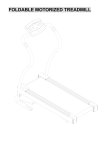
1
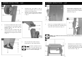
Please dispose of packaging for the product in a responsible
manner. It is suitable for recycling. Help to protect the
environment, take the packaging to the local amenity tip
and place into the appropriate recycling bin.
Never dispose of electrical equipment or batteries in with
your domestic waste. If your supplier offers a disposal facility please use it or alternatively use a recognised re-cycling
agent. This will allow the recycling of raw materials and help
protect the environment.
FOR HELP OR ADVISE ON THIS PRODUCT PLEASE CONTACT YOUR DISTRIBUTOR
Ref:070611
28
01541
Contractors Saw
Please read and fully understand the instructions in
this manual before operation. Keep this manual
safe for future reference
1
TROUBLESHOOTING
Problem
Possible cause
Possible solution
Table saw does not start:
•
•
•
•
•
Power Switch does not op- •
erate:
•
•
Mains lead is not connected to the mains
supply.
Circuit fuse is blown.
Circuit breaker has
tripped.
Mains lead or Switch is
damaged.
•
•
•
Power Switch contacts •
are burned out.
Capacitor is defective.
Wiring connections are •
loose or damaged.
•
Fuses or circuit breakers •
blow or open frequently:
•
•
•
Table Saw is noisy when •
running:
2
Motor is overloaded.
Fuses or circuit breakers
are wrong size or defective.
Dull saw blade.
Power Switch or motor is
defective.
•
•
•
•
Motor is loose or defec- •
tive.
27
Connect the mains
lead to the electrical
outlet.
Replace circuit fuse.
Reset circuit breaker.
Have the Mains lead or
Switch checked, repaired or replaced.
Have the Power Switch
checked, repaired or
replaced.
Have the Capacitor
checked, repaired or
replaced.
Have the wiring connections checked / repaired.
Feed work-piece more
slowly.
Replace fuses or circuit
breakers.
Replace the saw blade.
Have the Power Switch
or motor checked, repaired or replaced.
Have
the
Motor
checked /repaired.
CONTENTS
TROUBLESHOOTING
Problem
Possible cause
Motor is slow or weak:
•
•
•
•
Possible solution
Voltage from source is •
low.
Windings are burned
out or open.
•
NVR Switch is defective.
Circuit is overloaded
with appliances lights or •
other electrically powered equipment
•
Voltage from source is •
low.
Dull saw blade.
Sawdust inside table •
saw is blocking airflow. •
Request a voltage
check from the local
power company.
Replace the saw blade.
Clean out the saw
base.
blade teeth are dull.
•
Work-piece is warped.
Rip fence is not parallel •
with the saw blade.
Sharpen or replace the
blade.
Replace the workpiece.
Re-align the rip fence,
and lock it in position.
Rip Fence does not move •
smoothly:
Rip Fence is mounted •
incorrectly.
Remove, and reposition
the Rip Fence and lock
it in position.
Bevel & Height Handles are •
hard to turn:
Sawdust has collected •
on the mechanisms
inside the saw.
Clean and lubricate the
mechanisms inside the
base.
Table saw vibrates exces- •
sively:
•
•
Floor surface is uneven.
V-belt is damaged.
Saw blade is damaged.
Loose bolt, Screws,
Nuts.
•
Sit the saw on a level
surface.
Replace the V-belt.
Replace the Saw Blade.
Tighten all Hardware.
Motor regularly overheats:
•
Request a voltage
check from local power
company.
Have
the
Motor
checked, repaired or
replaced.
Have the NVR switch
checked, repaired or
replaced.
Do not use other appliances or electrically
powered equipment on
the same circuit when
using the Table Saw.
•
•
When ripping, the cut •
burns the work-piece, or •
stalls the motor:
•
•
•
26
•
•
•
Page No.
Description
3.
Contents
4.
General Safety Instructions
6.
Specific Safety Instructions
7.
Safety Symbols
7.
Getting To Know Your Saw
8.
Contents And Accessories
10.
Technical Specifications
11.
Guarantee
11.
Electrical Connection
12.
Assembly Instructions
22.
Operating Instructions
24.
Maintenance
26.
Troubleshooting
3
GENERAL SAFETY INSTRUCTIONS
MAINTENANCE….cont
Please read the following instructions carefully, failure to do so could lead to serious
personal injury.
When using electric tools, basic safety precautions should always be followed to reduce the risk of fire, electric shock and personal injury.
Read all these instructions before operating the tool and save this user manual for future reference.
SIP recommends that this tool should not be modified or used for any application
other than that for which it was designed. If you are unsure of its relative applications
do not hesitate to contact us and we will be more than happy to advise you.
KNOW YOUR POWER TOOL: Read and understand the owner's manual and labels affixed to the tool. Learn its applications and limitations, as well as the potential hazards
specific to this tool.
KEEP WORK AREA CLEAN AND WELL LIT: Cluttered work benches and dark areas invite
accidents. Floors must not be slippery due to oil, water or sawdust etc.
DO NOT USE THE TOOL IN DANGEROUS ENVIRONMENTS: Do not use power tools in
damp or wet locations, or expose them to rain. Provide adequate space surrounding
the work area. Do not use in environments with a potentially explosive atmosphere.
KEEP CHILDREN AND UNTRAINED PERSONNEL AWAY FROM THE WORK AREA: All visitors
should be kept at a safe distance from the work area.
STORE TOOLS SAFELY WHEN THEY ARE NOT IN USE: All tools should be stored in a dry,
locked cupboard wherever possible and out of the reach of children.
WEAR THE CORRECT CLOTHING: Do not wear loose clothing, neckties, rings, bracelets,
or other jewellery, which may get caught in moving parts. Non-slip footwear is recommended. Wear protective hair covering to contain long hair. Roll long sleeves up
above the elbow.
USE SAFETY GOGGLES AND EAR PROTECTION: Wear CE approved safety goggles at all
times, Normal spectacles only have impact resistant lenses, they are NOT safety
glasses. A face or dust mask should be worn if the operation is dusty and ear protectors (plugs or muffs) should be worn, particularly during extended periods of operation.
PROTECT YOURSELF FROM ELECTRIC SHOCK: When working with power tools, avoid
contact with any earthed items (e.g. pipes, radiators, hobs and refrigerators, etc.). It is
advisable wherever possible to use an RCD (residual current device) at the mains
socket.
STAY ALERT: Always watch what you are doing and use common sense. Do not operate a power tool when you are tired or under the influence of alcohol or drugs.
DISCONNECT THE TOOL FROM THE MAINS SUPPLY: When not in use, before servicing
and when changing accessories such as cutters, blades etc.
AVOID UNINTENTIONAL STARTING: Make sure the switch is in the OFF position before
connecting the tool to the mains supply.
NEVER LEAVE THE TOOL RUNNING / CONNECTED WHILST UNATTENDED: Turn off the tool
and disconnect it from the mains supply between jobs. Do not leave machine until it
comes to a complete stop.
4
Set the saw blade (4) to max. cutting depth (see page 22).
Take off the saw blade guard (2) (see page 21).
Take out the table insert (6) (see below).
Place the holder wrench (41) on the saw blade flange.
Using the wrench (40), turn out the screw (42) in the running direction of the saw blade.
Remove the saw blade (4) from the inner flange and pull out in an upwards direction.
Clean the blade flange thoroughly before fitting the new blade.
Mount and fasten the new saw blade in reverse order to above instructions.
Important: Note the running direction. The cutting angle of the teeth must point in
running direction, i.e. forwards (see the arrow on the blade guard).
Refit blade guard (2).
Check to make sure that all safety devices are properly mounted and in good working
condition before you begin working with the saw again.
Changing the table insert (Figure 38):
To prevent increased likelihood of injury the
table insert should be changed whenever
it is worn or damaged.
Remove the saw blade guard (2) (see
page 21).
Remove the countersunk head screws (38).
Take out the worn table insert (6).
To fit the replacement table insert, proceed in reverse order.
25
OPERATING INSTRUCTIONS….cont
MAINTENANCE
Important! Always turn the saw off and remove the plug from the mains supply before all maintenance and / or adjustments.
•
•
•
•
•
•
•
•
Remove dust and dirt regularly from the machine. Cleaning is best carried out
with a fine brush or a cloth.
Never use caustic agents to clean plastic parts.
Keep all safety devices, air vents and the motor housing free of dirt and dust as
far as possible.
Wipe the equipment with a clean cloth or blow it with compressed air at low
pressure.
We recommend that you clean the device immediately each time you have
finished using it.
Clean the saw regularly with a moist, not wet, cloth and some soft soap.
Do not use cleaning agents or solvents; these could attack the plastic parts of
the equipment.
Ensure that no water can seep into the electric parts of the saw.
GENERAL SAFETY INSTRUCTIONS...cont
DO NOT ABUSE THE MAINS LEAD: Never carry the tool by the mains lead or pull it to remove the plug from the mains socket. Keep the mains lead away from heat, oil and
sharp edges. If the mains lead is damaged, it must be replaced by the manufacturer
or its service agent or a similarly qualified person in order to avoid unwanted hazards.
CHECK FOR DAMAGED PARTS: Before every use of the tool, a guard or other part that is
damaged should be carefully checked to determine that it will operate correctly and
perform its intended function. Check for alignment of moving parts, free running of
moving parts, breakage of parts, and any other conditions that may affect its operation. A guard or other part that is damaged should be correctly repaired or replaced
by an authorized service centre unless otherwise indicated in this instruction manual.
Have defective switches replaced by an authorized service agent. Do not use the tool
if the switch does not turn it on and off.
KEEP ALL GUARDS IN PLACE: And in full working order.
MAINTAIN TOOLS WITH CARE: Keep tools sharp and clean for the best and safest performance. Follow instructions for lubricating and changing accessories. All extension
cables must be checked at regular intervals and replaced if damaged. Always keep
the hand grip on the tool clean, dry and free of oil and grease.
USE ONLY RECOMMENDED ACCESSORIES: Consult this user manual for recommended
accessories. Follow the instructions that accompany the accessories. The use of improper accessories may cause hazards and will invalidate any warranty you may
have.
REMOVE ADJUSTING KEYS AND WRENCHES: Form a habit of checking to see that keys
and adjusting wrenches are removed from the tool before every use.
SECURE THE WORKPIECE: Use clamps or a vice to hold the work-piece . This frees up
both hands to operate the tool.
DO NOT OVERREACH: Keep proper footing and balance at all times.
USE THE RIGHT TOOL: Do not use the tool or attachment to do a job for which it was
not designed.
DO NOT FORCE THE TOOL: It will do the job better and more safely at the rate which it
was designed.
DO NOT OPERATE POWER TOOLS IN EXPLOSIVE ATMOSPHERES: Do not use the tool in
the presence of flammable liquids, gases, dust or other combustible sources. Power
tools may create sparks which can ignite the dust or fumes.
DO NOT EXPOSE THE TOOL TO RAIN OR USE IT IN WET CONDITIONS: Water entering a
power tool will greatly increase the risk of electric shock.
HAVE YOUR TOOL REPAIRED BY A QUALIFIED PERSON: The tool is in accordance with the
relevant safety requirements. Repairs should only be carried out by qualified persons
using original spare parts, otherwise this may result in considerable danger to the user.
Changing the saw blade Fig. 37:
24
5
SPECIFIC SAFETY INSTRUCTIONS
1. Use only the blade flange specified for this tool.
2. Be careful not to damage the arbor, flange (especially the installing surface) or
NUT. Damage to these parts could result in blade breakage. And / or operator injury.
3. Make sure that the table base is properly secured so it will not move during operation.
4. For your safety; remove the chippings and work debris etc. from the table top and
from inside the extraction port before each operation.
5. Avoid cutting nails / screws etc.; Remove all obstructions from the work-piece before cutting.
6. Make sure that all keys and wrenches are removed before switching on the saw.
7. Be sure that the blade does not come into contact with the table and / or table
insert when the blade is in operation.
8. Always use the supplied push stick whenever possible.
9. Keep hands out of path of saw blade, never reach around saw blade.
10. Make sure the blade is clear of the work-piece before the switch is turned on.
11. Before making the first cut using the saw, turn the blade by hand to ensure nothing is catching, then turn the saw on and let it run for a while; Watch for vibration or
wobbling that could indicate poor installation or a poorly balanced blade. Adjust or
replace as necessary.
12. Allow the blade to run up to full speed before cutting.
13. Stop operation immediately if you notice anything abnormal.
14. Wait for the saw blade to stop completely and remove from mains supply before
servicing or adjusting tool.
15. Be alert at all times, especially during repetitive, monotonous operations. Don't
be lulled into a false sense of security. Blades are extremely unforgiving.
16. Use of improper accessories such as abrasive wheels may cause damage to
the saw and surrounding area as well as increasing the risk of injury.
17. Turn off the saw and wait for it to complete stop before moving work-piece or
changing settings.
18. Do not modify the saw to do tasks other than those intended.
19. Be sure to use a push stick (3) when making longitudinal cuts in work-pieces
smaller than 120 mm in width and wherever possible. A push stick is supplied with the
saw!
CAUTION: The warnings and cautions mentioned in this user manual
can not cover all possible conditions and situations that may occur. It
must be understood by the operator that common sense and caution
are factors which cannot be built into this product, but must be applied.
6
OPERATING INSTRUCTIONS….cont
The Rip-Fence (7) should be slid onto
the Rip-Fence carrier (17) from the
right hand side.
Set the Rip-Fence (7) to the required
distance from the blade, and lock in
place by pressing down on the ripfence lock lever (9).
The rip-fence should always run parallel to the blade.
On / Off (NVR) Switch:
Once fully assembled and adjusted, and all safety precautions have been followed;
the saw is ready to be run.
To start the saw; press the green (I) button.
To stop the saw; press the red (0) button.
Your SIP Contractors Saw is fitted with a safety NVR (No Volt Release) switch. This means
that if power is cut to the saw (such as in a power failure); the motor will not start to run
once the power is returned without the operator following the above instructions to restart the saw.
Using the wheel kit (15):
To swing the wheel kit out, lift the saw at the back (a) and push / pull the wheels backwards (15) (b).
Then lower the saw again, keeping it in this same position (c).
The saw is now standing on the wheels and can be transported by one person with the
aid of the handles (16).
Important: After transportation, the wheel kit (15) must immediately be retracted in order to ensure that the saw is standing securely on its legs. To do this, return the wheels
to their starting position by following the sequence in reverse.
23
SAFETY SYMBOLS
OPERATING INSTRUCTIONS
•
•
•
•
•
•
•
Always turn the saw off and remove the plug from the mains supply before
making any checks / adjustments.
After every new adjustment we recommend you to make a trial cut in order to
check the new settings.
Always turn the blade by hand prior to operation to ensure that nothing is catching or binding.
After switching on the saw, wait for the blade to reach its maximum speed of
rotation before commencing with the cut.
Take extra care when starting the cut!
When using the saw always ensure the operator as well as those in the
area wear ear protection.
When using the saw always ensure the operator as well as those in the
area wear eye protection.
Setting the blade height and angle:
•
Turn the blade height adjust handle (8)
clockwise to raise the cutting height,
and anti-clockwise to lower the blade
cutting height.
Loosen the angle locking screw (28) and
set the desired angle on the angle
scale (40).
Re-tighten the locking screw.
•
•
Some wood and wood composites have the potential to be highly
toxic; always wear a face mask when operating saw.
GETTING TO KNOW YOUR SAW
The angle adjustment function has an adjustable stop (39) at 0° und 45°. For angles slightly
greater than 45° or less than 0°, the angle stop
can be swung away.
Note: The blade height should be set to just above the work-piece height.
Rip-Fence:
The Rip-Fence (7) has two different guide faces
(23).
For thick material you should use the rip-fence extension (23) as shown in Fig. 34, for thin material
you must use the extension as shown in Fig. 35.
The Rip-Fence (7) should to be used when making
longitudinal cuts in wooden work-pieces.
The Rip-Fence (7) should be mounted on the righthand side of the saw blade (4).
22
7
GETTING TO KNOW YOUR SAW….cont
ASSEMBLY INSTRUCTIONS….cont
To adjust the rip fence carrier (17):
•
Raise the blade to its highest position
using the height adjust crank (8).
Fit the rip fence (7) over the carrier (17)
and slide the rip fence up to the
blade.
Slide the carrier so that the zero mark
on the scale (12) is directly under the
mark on the rip fence.
Lock the rip fence in position with the
rip fence clamp (9).
Ensure that the rip fence is level with
the main saw table and tighten the
nuts from fixing kit F previously fitted,
see Fig. 15 & 16 to secure in place.
•
•
•
•
CONTENTS AND ACCESSORIES
•
•
•
Mount the saw blade guard (2) on the riving knife (5) so that the screw (36) fits
through the hole (35) in the riving knife. Fig. 31.
Do not tighten the screw (36) too far – the blade guard must be able to move
freely.
Fasten the extractor hose (13) to the extractor adapter (14) and to the extractor
socket of the blade guard (2). Fig. 31 & 32.
A suitable extractor system has to be connected to the outlet of the extractor adapter
(14).
To remove the saw blade guard, proceed in reverse order.
Important! The blade guard (2) must always be lowered over the blade prior to each
operation.
8
21
CONTENTS AND ACCESSORIES….cont
ASSEMBLY INSTRUCTIONS….cont
•
•
•
The stop rail must move parallel to
the saw table at a distance of approximately 1 mm.
To achieve this; loosen the bolts for
the sliding rail mounting brackets
(19) and adjust in such a way that
there is a 1 mm gap between the
rail and the saw table along the
length of the rail.
Re-tighten the bolts to secure in position. See Fig. 27.
To fit the rear table (10):
•
Loosely fit the rear extension table to
the rear of the main table with the
bolts, spacers, washers and nuts from
fixing kit C; ensuring that the spacer
sits between the main table and the
extension table. Fig. 28.
Ref No.
Description
Ref No.
Description
1.
Main Saw Assembly
17.
Rip Fence Carrier
2.
Blade Guard
18.
Leg Set
3.
Push Stick
19.
Sliding Rail Support Brackets
4.
Blade
20.
Sliding Rail
5.
Riving Knife
21.
Extraction Hose Mount
6.
Table Insert
22.
Wheel Kit Support Brackets
7.
Rip Fence
23.
Rip Fence Extension
8.
Blade Height Adjust Handle
24.
Leg Support Struts
9.
Rip Fence Clamp
25.
Rubber Feet
10.
Rear Extension Table
26.
Push Stick Hook
11.
On/Off (NVR) Switch
27.
Rear Table Supports
12.
Rip Fence Carrier Scale
28.
Blade Angle Adjust / Lock
13.
Extraction Hose
29.
Spanner / Wrench
14.
Extraction Port
30.
Spanner / Wrench
15.
Wheel Set
31.
Sliding Carriage Stop Rail
16.
Moving Handle
32.
Sliding Rail Carriage
Note: It would be helpful to have 2 persons to carry out this part of the build.
•
Now fit the rear table supports (27) to
the rear leg brace (24) and the back of
the rear extension table using the remaining bolts, washers and nuts from
fixing kit H. See Fig. 29.
Use a flat edge to ensure that the rear
extension table is level with the main
table and tighten all nuts / bolts to secure.
•
20
9
CONTENTS AND ACCESSORIES….cont
Ref.
D
ASSEMBLY INSTRUCTIONS….cont
Nut
Bolt
A.
M8 lock nut
N/A
8x24 mm
8x15 mm
Lock lever & Plastic washer / spacer
B.
N/A
M10x65
10x24 mm
N/A
Plastic washer / spacer
C.
M8
M8x25
8x16 mm
8 mm
Spacer
D.
N/A
N/A
6x12 mm
N/A
M6 x 15 Cap-head bolt
E.
N/A
N/A
N/A
N/A
M6x40 Cap-head bolt
M6 Thumb-nut
F.
M6
N/A
6x12 mm
6 mm
M6 x 15 mm Coach bolt
G.
N/A
N/A
5x10 mm
N/A
15 mm self tapping screw
H.
M6
M6x15
6x12 mm
6 mm
N/A
I.
M8
M8x20
8x16 mm
8 mm
N/A
Desc.
Washer Spring Washer
Misc.
•
Slide the carriage (32) over the sliding rail (20) from either the front of
the back of the rail as shown in Fig.
24.
Caution: To avoid damage or injury, do not attempt to assemble or use the
saw if any parts are missing or damaged.
IF ANY ITEMS ARE MISSING or DAMAGED; CONTACT YOUR DISTRIBUTOR
IMMEDIATELY.
TECHNICAL SPECIFICATIONS
Part number
01541
Input voltage
230v ~ / 50hz
Power
2.2 kw (3 hp)
Maximum speed (no load)
2860 rpm
Blade size
Ø 315 mm x 30 mm bore
Maximum Depth Of Cut @ 45°
58 mm
Maximum Depth Of Cut @ 90°
83 mm
Main Table Size
790 mm x 580 mm
Extension Table Size
790 mm x 400 mm
Net Weight
52 Kg
10
•
If there is too much movement /
play between the guide bearings
and the sliding rail; the lower bearing (33) should be adjusted so that
the carriage slides freely. See Fig.
25.
•
19
The carriage stops (fixing kit E)
should be fitted to the holes either
end of the sliding rail as shown in
Fig. 26. This will stop the carriage
from falling off either end of the rail.
ASSEMBLY INSTRUCTIONS….cont
GUARANTEE
Guarantee:
•
Using the 4 cap head bolts from fixing kit D; attach the sliding rail (20)
to the 2 support brackets (19) in a
way so that the rail overhangs more
to the front than the rear. See Fig.
21.
This SIP Contractors Saw is covered by a 24 month parts and labour warranty covering
failure due to manufacturers defects. This does not cover failure due to misuse or operating the machine outside the scope of this manual.
In the unlikely event of warranty claims, contact your distributor as soon as possible.
Proof of purchase will be required before any warranty can be honoured.
Note: Proof of purchase will be required before any warranty can be honoured.
ELECTRICAL CONNECTION
•
•
Fit the sliding carriage stop rail (31)
to the sliding rail carriage (32) as
shown in Fig. 22 & 23 using fixing kits
A & B.
Ensure that both spacers (29) are
fitted between the rail and the carriage.
Connecting to the power supply:
This SIP Contractors Saw is fitted with a standard 230v ~ 13 amp plug. Before using the
saw, inspect the mains lead and plug to ensure that neither are damaged. If any
damage is visible have the saw inspected / repaired by a suitably qualified person. If
it is necessary to replace the plug a heavy duty impact resistant plug would be preferable.
The wires for the plug are coloured in the following way:
Note: Do not over-tighten; the stop rail must remain free moving for the
purpose of angle adjustment.
•
During assembly; ensure that the spring
washer from fixing kit A is fitted between
the locking nut and the washer on the
lock lever.
The lock lever should be assembled /
tightened so that the sliding carriage
stop rail can be moved when the lever is
released, but can not be moved when
the lever is locked.
•
18
Yellow / green
Blue
Brown
Earth
Neutral
Live
As the colours of the wires may not correspond with the markings in your plug, proceed as follows: The wire which is coloured blue, must be connected to the terminal
marked with N or coloured black. The wire which is coloured brown, must be connected to the terminal, which is marked L or coloured red. The wire which is coloured
yellow / green should be connected to the terminal which is coloured the same or
marked
Always secure the wires in the plug terminal carefully and tightly. Secure the cable in
the cord grip carefully.
11
ASSEMBLY INSTRUCTIONS….cont
ELECTRICAL CONNECTION….cont
Warning: Never connect live or neutral wires to the earth terminal of the
plug. Only fit an approved plug with the correct rated fuse (13 amp). If in
doubt consult a qualified electrician.
•
Note: Always make sure the mains supply is of the correct voltage and the
correct fuse protection is used. In the event of replacing the fuse always
use a 13A fuse.
•
Note: If an extension lead is required in order to reach the mains supply;
ensure that this too is rated for the correct voltage and fuse rating (16
amps).
Loosely fit the 2 sliding rail support
brackets (19), one at the front left of
the saw and one at the rear left;
using the bolts previously removed
in Fig. 14 and the last 2 bolts ,
washers and nuts from fixing kit I as
shown in Fig. 18 - 19).
The lugs on both brackets should
face the front of the saw.
Note: The cross section of the extension lead should be checked so that it
is of sufficient size so as to reduce the chances of voltage drops.
•
ASSEMBLY INSTRUCTIONS
•
•
•
•
•
•
•
Unpack the contractors saw and check it for damage which may have occurred in transit.
The machine should to be set up where it can stand firmly on a flat level surface.
All covers and safety devices have to be correctly fitted and in full working order
before the machine is switched on.
The saw blade should run freely.
When working with wood that has been processed before, watch out for foreign
bodies such as nails or screws etc. Always check and remove prior to running
the work-piece through the saw.
Before you actuate the On/Off switch, make sure that the saw blade is correctly
fitted and that the machines moving parts run smoothly.
Before you connect the machine to the power supply, make sure the data on
the rating plate is the same as that for your mains supply.
At the same time, at the rear of the
saw; fit the extraction hose mount
(21) using the same bolts. As shown
in Fig. 19.
•
•
•
•
Place the main saw assembly (1), table face down, onto a flat level surface.
Place the saw onto cardboard, or similar, to reduce the risk of damage.
12
17
Whilst on a flat level surface; ensure
that the leg-set is aligned correctly
and that the main table is level.
Fully tighten all of the screws for the
leg-set.
Remove the transit packing as
shown in Fig. 20.
ASSEMBLY INSTRUCTIONS….cont
ASSEMBLY INSTRUCTIONS….cont
•
•
•
•
•
Fit the 3 small coach-bolts, washers
and nuts (fixing kit F) loosely into the
3 holes on the front edge of the table as shown in Fig. 15.
Carefully remove the end cap from
the rip-fence carrier (17).
Slide the channel on the back of the
carrier (17) over the heads of the
coach-bolts (H) as shown in Fig. 16.
Replace the cap.
•
•
•
16
Fit the 2 short leg struts (24) to the 2
ends of the leg-set (18), and the 2
long leg struts (24) to the 2 sides of
the leg set.
Loosely secure the struts to the leg set
using bolts, washers and nuts from
fixing kit (I) as shown in Fig. 6, 7 and 8.
Fit the push stick hook to the front
right hand leg as shown in Fig. 17.
13
Fit the 4 legs from the leg-set (18)
loosely to the main saw assembly (1)
using bolts, washers and nuts from fixing kit (I) as shown in Fig. 5.
ASSEMBLY INSTRUCTIONS….cont
ASSEMBLY INSTRUCTIONS….cont
•
•
•
•
•
Working from the inside; fit the 2
wheel kit brackets (22) to the rear
legs from the leg-set (18).
Secure in place with bolts, washers
and nuts from fixing kit (H) as shown
in Fig. 9.
•
Fit the four rubber feet (25) to each
of the legs from the leg-set (18) by
pressing them over the feet as
shown in Fig. 10.
Secure the feet in place with the
metal brackets and bolts, washers
and nuts from fixing kit (H) as shown
in Fig. 11.
Fit the switch / plug box to the outside
of the left front leg using the 2 x self
tapping screws and 2 x washers (set G)
as shown in Fig. 12.
Fit the 2 x moving handles (16) to the
front legs using the bolts, washers and
nuts from set H; as shown in Fig. 13.
Note: The handles should move freely and retract automatically as you let
go of them.
•
Turn the saw the correct way up,
and stand on a firm level surface.
•
Note: At least 2 persons are required to turn the saw the correct way to avoid personal injury
and / or machine damage.
14
15
Remove the 2 bolts from the left
hand side at the front of the saw; as
previously fitted in Fig. 5, and the 2
on the same side at the rear of the
saw as shown in Fig. 14.