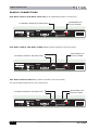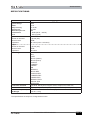
1
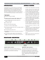
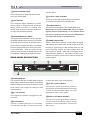
TFX256 PRO
Digital Effect Processor
SAFTY PRECAUTIONS
SAFETY PRECAUTIONS!
WARNING - TO REDUCE THE RISK OF FIRE OR ELECTRIC SHOCK, DO NOT
EXPOSE THIS UNIT TO RAIN OR MOISTURE.
Do not allow water or liquids to be spilled into this unit. If the unit has been exposed to rain or liquids, please
unplug the power cord immediately from the outlet (with DRY HANDS) and get a qualified service technician
to check it. Keep this unit away from heat sources such as radiators, heat registers, stoves, etc.
This unit contains no user-serviceable parts. Refer all service needs to a
qualified service engineer through a Phonic dealer.
This triangle on your component alerts you
to the presence of uninsulated “ dangerous voltage” inside the enclosure that may
be sufficient to constitute a risk of shock.
This triangle on your component alerts you
to important operating and maintenance instructions in this accompanying literature.
CAUTION:
TO REDUCE THE RISK OF ELECTRIC SHOCK, DO NOT REMOVE COVERS (OR
BACK). NO USER-SERVICEABLE PARTS ARE INSIDE. REFER ALL SERVICING TO
A QUALIFIED SERVICE PERSONNEL.
Keep this unit clean by using a soft dry brush and occasionally wiping it with a damp cloth. Do not use
any other solvents, which may damage the paint or plastic parts. Regular care and inspection will be
rewarded by a long product life and maximum reliability.
This unit was carefully packed at the manufacturing site and the packing box was designed to protect the
unit from rough handling. We recommend that you carefully examine the packaging and its contents for any
signs of physical damage which may have occurred during transportation.
If the unit is damaged: Notify your dealer and the shipping company immediately.
Claims for damage or replacement may not be granted if not reported properly or in a timely manner.
Page 2
TFX256 PRO USER’S MANUAL
CONTENTS
TFX256 PRO
USER’S MANUAL
INTRODUCTION...................................................4
FEATURES...........................................................4
GETTING STARTED.............................................4
FRONT-PANEL DESCRIPTION.............................5
INPUT LEVEL CONTROL
PEAK (L/R) INDICATORS
MIX (DRY/WET) CONTROL
LED DISPLAY
EFFECT MODES CHART
EFFECT MODE, KEYS
PATTERN SELECTOR
OUTPUT CONTROL
POWER SWITCH
EFFECT 4: DELAY-1 (ST)................................7
EFFECT 5: DELAY-2 (MONO).........................8
EFFECT 6: CHORUS.......................................8
EFFECT 7: FLANGER......................................9
EFFECT 8: PHASER........................................9
EFFECT 9: PAN.............................................10
EFFECT 10: TREMOLO.................................10
EFFECT 11: DELAY + REV............................11
EFFECT 12: CHORUS + REV........................11
EFFECT 13: FLANGER + REV....................12
EFFECT 14: PHASER + REV........................12
EFFECT 15: TREMOLO + REV.....................13
EFFECT 16: SPECIAL EFX...........................13
EFFECT 17: GATED + REV...........................13
SAMPLE CONNECTIONS................................14
One mono cord in, one mono cord out
One mono cord in, two mono cords out
Two mono cords in and out
REAR-PANEL DESCRIPTION ...............................5
AC 10V IN INLET
FOOTSWITCH
SPECIFICATIONS.............................................15
OUTPUT (LEFT & RIGHT)
INPUT (LEFT/MONO & RIGHT)
PRESET PROGRAMS..........................................6
EFFECT 1: ROOM ...............................................6
EFFECT 2: HALL .................................................6
EFFECT 3: PLATE ...............................................7
TFX256 PRO USER’S MANUAL
Page 3
INTRODUCTION / FEATURES / GETTING STARTED / FRONT-PANEL DESCRIPTION
INTR
ODUCTION
INTRODUCTION
GETTING ST
AR
TED
STAR
ARTED
Congratulations on your purchase of the t.racks TFX256
PRO digital reverberator. The TFX256 PRO is a high
quality and easy-to-use stereo digital reverberator. To
take full ad-vantage of the TFX256 PRO’s functions,
and enjoy a longand trouble-free use, please read this
user’s manualcarefully and keep it for future reference.
1.
2.
FEATURES
256 effect programs available
Programs include reverb, delay, flanger, chorus,
tremolo, phaser, pan effects and combinations
3.
32-40 bit digital signal processing plus 24 bit
AD/DA conversions
4.
True stereo reverb
Easy-to-read 3-digit LED display
Compact 1U rack-mountable design
Foot switch jacks allow the user to remotely activate
and mute the effect
Auto-bypass when power is off.
Signal and clip LEDs allow easy setup of the optimum
input level
A professional quality digital reverb designed for
musical instruments, recording, and sound reinforcement
5.
6.
7.
Check the AC voltage before connecting
the plug. Choose the main supply for the
sound system with care. Do not share
sockets or earthing with light dimmers.
Run audio cables separately from dimmer
wiring, using balanced lines wherever
possible. If necessary, cross audio and
lighting cables at 90o right angles to minimize the possibility of interference. Keep
unbalanced cabling as short as possible.
Check your cables regularly and label each
end for easy identification.
Before switching on the main power, keep
all output rotary faders all the way down to
prevent damage or excessive noise
caused by bad level adjustment, wrong
wiring, defective cables,or bad
connections.
Always turn on the TFX256 PRO before
the power amplifier; turn off the TFX256
PRO after turning off the amplifier.
Always turn off the unit before connecting
or disconnecting the unit to the power
source.
Never use any solvents to clean the unit.
Clean it with a soft, dry cloth.
FR
ONT
-P
ANEL DESCRIPTION
ONT-P
FRONT
-PANEL
2 MIX (DRY / WET) CONTROL
1 INPUT LEVEL CONTROL
The input level control sets the level going into the
This control sets the balance between the unaf-
TFX256 PRO. You should set the level so that Peak fected signal coming through the inputs and the
(2) indicators only flash RED occasionally.
effects being generated by the TFX256 PRO i.e.
the balance of wet (effect) and dry (no effect)
sounds. By keeping the Mix somewhere in the
center, a blend of dry and wet signal can be
achieved.
Page 4
TFX256 PRO USER’SMANUAL
REAR-PANELDESCRIPTION
3 EFFECT MODES CHART
vate the effects.
This chart shows you what 256 effect modes
are in the TFX256 PRO.
6 OUTPUT LEVEL CONTROL
4 LED DISPLAY
This 7-segment display indicates the current
effect program in Program mode. When the
display shows the letter “C” flashing, this
means either the right or left input signals are
too high and should be reduced.
This rotary control sets the level going to the amplifier
or mixer from the output of the TFX256 PRO
7 POWER SWITCH
This switch turns the power of the TFX256 PRO on/off.
Whenpower is off, the TFX256 PRO will be in signal
bypass position automatically i.e. this feature allows
the direct signal to pass through the TFX256 PRO
5 PROGRAM SELECT KNOB
even when the power is not switched on.
Turning this control will allow users to 'preview'
the different digital effects. Pushing it in will load
the preset. If this control is not pushed within a
few seconds of changing the effect, the TFX256
PRO will automatically revert back to the previously loaded effect. When this control is held
down for a few seconds, the digital effects b will
be bypassed. Holding it down again will reacti-
REAR-PANEL DESCRIPTION
9 LOAD INDICATOR
This small LED indicator, located within the digital
effect display, will flash when users are previewing
different effects (when turning the program select
knob). When a new program is loaded, this LED
will stop flashing.
8 SIGNAL INDICATORS
These 2 small LED indicators, located within the digital
effect display, show when either the left or right inputs are
receiving a signal (the left LED indicates when the left
input is receiving a signal, the right indicates when the
right receives a signal). When the LCD display (above
these indicators) flashes “C”, the signal in the left or right
channel is excessive, and should be reduced to keep the
audio’s integrity.
to switch the effect mute on/off (bypass).
12 OUTPUT (LEFT & RIGHT)
10 AC 10V IN INLET
There are 1/4” phone jacks which connect to
devices such as the effects returns on a mixing
console or power amplifier inputs. For mono
applications, use the “Left” output.
The supplied AC Adapter is plugged into this
connector.
13 INPUT (LEFT/MONO & RIGHT)
This is a 1/4” stereo phone jack. If a foot switch
There are 1/4” phone jacks which connect to
sources such as the effects sends of mixing
consoles. For mono applications, use the “Left/
is connected to this jack, you can use your foot
Mono” input.
11 FOOTSWITCH
TFX256 PRO USER’S MANUAL
Page 5
PRESET PROGRAMS
PRESET
PROGRAMS
EFFECT 1: ROOM
7 Segment LED
Room
1
2
3
4
5
6
7
8
9
10
11
12
13
14
15
16
ROOM
1
2
3
4
5
6
7
8
9
10
11
12
13
14
15
16
REV-TIME PREDELAY HI-RATIO
0.05
40
0.5
0.05
0
0.6
0.4
0
0.95
0.4
0
0.93
0.45
5
0.95
0.45
30
0.9
0.6
0
0.9
0.6
6
0.92
0.65
22
1
0.9
6
0.96
1
1
10
1.2
15
0.98
1.4
0.98
60
0
1.4
0.96
1
1.6
22
3.85
0.96
25
HPF
80
0
382
430
500
0
550
0
0
0
500
410
0
22
0
0
LPF
2.5K
1.8K
9K
1.25K
12.5K
6.3K
2.36K
5.6K
19K
8K
20K
9.5K
5.6K
6.7K
10.6K
4.75K
DRY/WET
0~100
0~100
0~100
0~100
0~100
0~100
0~100
0~100
0~100
0~100
0~100
0~100
0~100
0~100
0~100
0~100
REV-TIME PREDELAY HI-RATIO
0.9
0
0.9
20
0.95
1
1.95
40
0.98
1.75
48
0.98
1.8
20
0.83
1.85
40
0.95
1.9
30
0.98
2.2
25
0.99
100
0.7
2.3
2.45
30
0.95
2.5
0.8
40
2.5
0
4
2.7
1
85
2.7
0.85
20
2.8
0.97
40
3.3
0.85
75
HPF
0
26
0
0
0
340
675
0
0
25
85
75
40
0
0
63
LPF
9K
10.6K
15k
9.5K
4.25K
7.1K
8.5K
2.24K
6.7K
8.5K
12.5K
3.15K
12.5K
8K
8.5K
10K
DRY/WET
0~100
0~100
0~100
0~100
0~100
0~100
0~100
0~100
0~100
0~100
0~100
0~100
0~100
0~100
0~100
0~100
EFFECT 2: HALL
7 Segment LED
Hall
17
18
19
20
21
22
23
24
25
26
27
28
29
30
31
32
Page 6
HALL
1
2
3
4
5
6
7
8
9
10
11
12
13
14
15
16
TFX256 PRO USER’S MANUAL
PRESET PROGRAMS
EFFECT 3: PLATE
7 Segment LED
Plate
33
34
35
36
37
38
39
40
41
42
43
44
45
46
47
48
PLATE
1
2
3
4
5
6
7
8
9
10
11
12
13
14
15
16
REV-TIME PREDELAY HI-RATIO
0.55
0
1
0.55
0
1
0.75
20
1
0.9
12
0.98
1
10
1
1.2
25
1
35
1
1.3
1.8
30
0.98
2
1
1
1
2.25
25
2.6
180
0.97
2.75
30
0.98
3
0
1
5
0.99
3
0.98
3.35
1
3.8
20
0.85
HPF
625
625
0
0
0
20
0
80
67
42
0
0
625
0
0
0
LPF
20K
20K
12.5K
12.5K
10.6K
7.1K
20K
12.5K
20K
20K
15K
4.25K
20K
8K
16K
1.4K
DRY/WET
0~100
0~100
0~100
0~100
0~100
0~100
0~100
0~100
0~100
0~100
0~100
0~100
0~100
0~100
0~100
0~100
EFFECT 4: DELAY-1 (ST)
7 Segment LED
Delay-1(ST)
49
50
51
52
53
54
55
56
57
58
59
60
61
62
63
64
DELAY-1(stereo)
1
2
3
4
5
6
7
8
9
10
11
12
13
14
15
16
L-DELAY
0.16
0.16
0.16
0.16
0.16
0.16
0.16
0.52
0.6
0.6
0.8
0.21
0.14
0.25
0.03
0.3
R-DELAY
0.03
0.08
0.08
0
0
0
0
0.2
0.2
0.2
0.3
0.2
0.05
0.05
0.06
0.06
TFX256 PRO USER’S MANUAL
C-DELAY
0.03
0.16
0
0.18
0.16
0.16
0.16
0.5
0.6
0.6
0.5
0.2
0.16
0
0.06
0
FB-DELAY
0.04
0
0
0
0.14
0.2
0.21
0.3
0.4
0.4
0.7
0.1
0.16
0.5
0.05
0.6
Page 7
PRESET PROGRAMS
EFFECT 5: DEALY-2 (MONO)
7 Segment LED
Delay-2(MONO)
65
66
67
68
69
70
71
72
73
74
75
76
77
78
79
80
DELAY-2(mono)
1
2
3
4
5
6
7
8
9
10
11
12
13
14
15
16
L-DELAY
0
0
0
0
0
0
0
0
0
0
0
0
0
0
0
0
R-DELAY
0
0
0
0
0
0
0
0
0
0
0
0
0
0
0
0
C-DELAY
0.5
0.5
0.15
0.15
0.15
0.2
0.2
0.4
0
0
0
0
1.2
1.2
0.5
0.15
FB-DELAY
0.3
0.3
0.1
0.03
0.15
0.3
0.2
0.4
0.3
0.4
0.4
0.55
1
1.2
1
0.4
PHASE
180
180
0
0
180
180
180
0
180
0
180
180
0
180
0
180
LPF
7.1K
6K
8K
6.3K
10K
500
8K
1.25K
10K
1K
10K
500
10K
850
10K
10K
EFFECT 6: CHORUS
7 Segment LED
Chorus
81
82
83
84
85
86
87
88
89
90
91
92
93
94
95
96
Page 8
CHORUS
1
2
3
4
5
6
7
8
9
10
11
12
13
14
15
16
LFO
0.3
0.8
1.2
1.8
2.2
3.6
3.2
4
5.6
6.4
7.5
7.8
8.4
8.8
9.2
10
PER-DELAY
2
5
20
1
60
15
30
90
120
200
88
80
50
10
5
115
TFX256 PRO USER’S MANUAL
PRESET PROGRAMS
EFFECT 7: FLANGER
7 Segment LED
Flanger
97
98
99
100
101
102
103
104
105
106
107
108
109
110
111
112
FLANGER
1
2
3
4
5
6
7
8
9
10
11
12
13
14
15
16
LFO
0.1
0.3
0.6
0.7
1
1
1.6
1.6
2
2
2
2.6
2.8
2.8
4.6
4.6
PER-DELAY
2
6
10
15
1
10
20
20
1
2
2
2
6
4
2
4
PHASE
180
0
180
180
180
180
180
180
180
180
180
180
180
180
180
180
PHASER
1
2
3
4
5
6
7
8
9
10
11
12
13
14
15
16
LFO
0.1
0.4
0.8
1.4
2.2
2.6
3.3
4
4.8
5.2
5.8
6
6
7.2
7.8
10
DELAY
3.5
0.6
3.2
0.6
1.6
4
1
2.8
1
0.1
0.8
1.2
3.2
5
2.6
5
PHASE
180
90
180
180
180
180
180
180
180
180
180
90
180
180
180
180
EFFECT 8: PHASER
7 Segment LED
Phaser
113
114
115
116
117
118
119
120
121
122
123
124
125
126
127
128
TFX256 PRO USER’S MANUAL
Page 9
PRESET PROGRAMS
EFFECT 9: PAN
7 Segment LED
Pan
129
130
131
132
133
134
135
136
137
138
139
140
141
142
143
144
PAN
1
2
3
4
5
6
7
8
9
10
11
12
13
14
15
16
SPEED
0.1
0.4
0.8
1.2
0.1
0.4
0.8
1.2
0.1
0.4
0.8
1.2
1.8
1.8
1.8
3.4
DEPTH
100
100
100
100
100
100
100
100
100
100
100
100
100
100
100
100
TYPE
L-->R
L-->R
L-->R
L-->R
R-->L
R-->L
R-->L
R-->L
R<-->L
R<-->L
R<-->L
R<-->L
L-->R
R-->L
R<-->L
R<-->L
EFFECT 10: TREMOLO
7 Segment LED
Tremolo
145
146
147
148
149
150
151
152
153
154
155
156
157
158
159
160
Page 10
TREMOLO
1
2
3
4
5
6
7
8
9
10
11
12
13
14
15
16
SPEED
0.5
0.8
1
1.2
1.6
2
2.4
3
3.4
4
4.4
5.2
6
6.6
8
10
TFX256 PRO USER’S MANUAL
DEPTH
100
100
100
100
100
100
100
100
100
100
100
100
100
100
100
100
PRESET PROGRAMS
EFFECT 11: DELAY + REV
7 Segment LED
Delay+Rev
161
162
163
164
165
166
167
168
169
170
171
172
173
174
175
176
DELAY+REV
1
2
3
4
5
6
7
8
9
10
11
12
13
14
15
16
DELAY-1
1
2
3
4
5
6
7
8
9
10
11
12
13
14
15
16
REV
ROOM1
ROOM7
ROOM11
ROOM12
ROOM14
ROOM15
HALL1
HALL3
HALL6
HALL11
HALL15
HALL16
PLAT1
PLAT3
PLAT6
PLAT12
CHORUS+REV
1
2
3
4
5
6
7
8
9
10
11
12
13
14
15
16
CHORUS
1
2
3
4
5
6
7
8
9
10
11
12
13
14
15
16
REV
ROOM1
ROOM7
ROOM11
ROOM12
ROOM14
ROOM15
HALL1
HALL3
HALL6
HALL11
HALL15
HALL16
PLAT1
PLAT3
PLAT6
PLAT12
EFFECT 12: CHORUS + REV
7 Segment LED
Chorus+Rev
177
178
179
180
181
182
183
184
185
186
187
188
189
190
191
192
TFX256 PRO USER’S MANUAL
Page 11
PRESET PROGRAMS
EFFECT 13: FLANGER + REV
7 Segment LED
Flanger+Rev
193
194
195
196
197
198
199
200
201
202
203
204
205
206
207
208
FLANGER+REV
1
2
3
4
5
6
7
8
9
10
11
12
13
14
15
16
FLANGER
1
2
3
4
5
6
7
8
9
10
11
12
13
14
15
16
REV
ROOM1
ROOM7
ROOM11
ROOM12
ROOM14
ROOM15
HALL1
HALL3
HALL6
HALL11
HALL15
HALL16
PLAT1
PLAT3
PLAT6
PLAT12
PHASER
1
2
3
4
5
6
7
8
9
10
11
12
13
14
15
16
REV
ROOM1
ROOM7
ROOM11
ROOM12
ROOM14
ROOM15
HALL1
HALL3
HALL6
HALL11
HALL15
HALL16
PLAT1
PLAT3
PLAT6
PLAT12
EFFECT 14: PHASER + REV
7 Segment LED
Phaser+Rev
209
210
211
212
213
214
215
216
217
218
219
220
221
222
223
224
Page 12
PHASER+REV
1
2
3
4
5
6
7
8
9
10
11
12
13
14
15
16
TFX256 PRO USER’S MANUAL
PRESET PROGRAMS
EFFECT 15: TREMOLO + REV
7 Segment LED
Tremolo+Rev
225
226
227
228
229
230
231
232
233
234
235
236
237
238
239
240
TREMOLO+REV
1
2
3
4
5
6
7
8
9
10
11
12
13
14
15
16
REV
ROOM1
ROOM7
ROOM11
ROOM12
ROOM14
ROOM15
HALL1
HALL3
HALL6
HALL11
HALL15
HALL16
PLATE 1
PLATE 3
PLATE 6
PLATE 12
TREMOLO
1
2
3
4
5
6
7
8
9
10
11
12
13
14
15
16
SPECIAL EFX
1
2
3
4
5
6
7
8
9
10
11
12
DELAY-1-1
DELAY-1-1
DELAY-1-1
CHORUS-2
CHORUS-5
TREMOLO-6
TREMOLO-12
PHASER-5
PHASER-5
FLANGE-1
PHASER-7
PAN-2
FLANGE-3
CHORUS-4
PHASER-7
FLANGE-1
PHASER-10
FLANGE-11
CHORUS-4
FLANGE-9
TREMOLO-12
TREMOLO-6
PAN-2
FLANGE-3
EFFECT 16: SPECIAL EFX
7 Segment LED
Special efx
241
242
243
244
245
246
247
248
249
250
251
252
EFFECT 17: GATED + REV
7 Segment LED
Gated+Rev
253
254
255
256
GATED-REV
1
2
3
4
THRESHOLD
-20
-20
-20
-20
ATTACK
0
0
0
200
TFX256 PRO USER’S MANUAL
RELEASE
0.02
0.5
0.1
0.01
REV
PLAT-1
PLAT-8
HALL-15
HALL-16
Page 13
SAMPLE CONNECTIONS
SAMPLE CONNECTIONS
ONE MONO CORD IN, ONE MONO CORD OUT (to an amplification system or mixer input)
TO MIXING CONSOLE OR AMPLIFIER
INSTRUMENT OF
EFFECTS SEND
ONE MONO CORD IN, TWO MONO CORDS OUT (to a stereo amplifier or two mixer inputs)
TO MIXING CONSOLE OR AMPLIFIER
INSTRUMENT OF
EFFECTS SEND
TWO MONO CORDS IN AND OUT (to a stereo amplifier or two mixer inputs)
This can be stereo signal in/out or mono signal in/out.
TO MIXING CONSOLE OR AMPLIFIER
Page 14
TFX256 PRO USER’S MANUAL
INSTRUMENT OF
EFFECTS SEND
SPECIFICATIONS
SEPCIFICATIONS
Frequency Response
Dynamic Range
AD/DA
DSP processing
Sampling rate
Maximum Input Level
Residual Noise
T.H.D.
20Hz ~ 20kHz
90dB
24-bit
32~40-bit
44.1kHz
0dB
< -80dB (20Hz ~ 20kHz)
< .05% (typical)
Input
Number of Channel:
Nominal Level:
Impedance:
2 (phone jack)
-20dB
20k ohms (mono: 10k ohms)
Output
Number of Channel:
Nominal Level:
Impedance:
Effect Programs
Front Panel Controls
Real Panel Jack
Dimensions (WxHxD)
Net Weight
2 (phone jack)
-20dB
600 ohms
ROOM
HALL
PLATE
DELAY-1(stereo)
DELAY-2(mono)
CHORUS
FLANGER
PHASER
PAN
TREMOLO
DELAY+REV
CHORUS+REV
FLANGER+REV
PHASER+REV
TREMOLO+REV
SPECIAL EFX
GATED-REV
Input level, Mix-dry/wet, Program select, Output level, Power Sw.
2 Input phone jacks, 2 Output phone jacks, foot Sw- phone jack, DC jack
19"x1.75"x4.2" / 483 x 44 x 107mm (1U)
2.64 lbs / 1.2 kg
The specifications are subject to change without notice.
TFX256 PRO USER’S MANUAL
Page 15