1
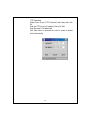
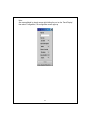
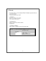
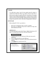
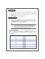
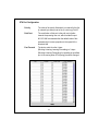
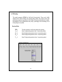
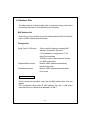
FCC Certifications
This Equipment has been tested and found to comply with the limits for a Class A
digital device, pursuant to part 15 of the FCC Rules. These limits are designed to
provide reasonable protection against harmful interference when the equipment is
operated in a commercial environment. This equipment generates, uses, and can
radiate radio frequency energy and, if not installed and used in accordance with
the instruction manual, may cause harmful interference to radio communications.
Operation of this equipment in a residential area is likely to cause harmful
interference in which case the user will be required to correct the interference at
his own expense.
This device complies with Part 15 of the FCC Rules. Operation is subject to the
following two conditions: (1) this device may not cause harmful interference, and
(2) this device must accept any interference received; including interference that
may cause undesired operation.
CE Mark Warning
This equipment complies with the requirements relating to electromagnetic
compatibility, EN 55022 class A for ITE, the essential protection requirement of
Council Directive 89/336/EEC on the approximation of the laws of the Member
States relating to electromagnetic compatibility.
Company has an on-going policy of upgrading its products and it may be possible
that information in this document is not up-to-date. Please check with your local
distributors for the latest information. No part of this document can be copied or
reproduced in any form without written consent from the company.
Trademarks:
All trade names and trademarks are the properties of their respective companies.
Copyright © 2004, All Rights Reserved.
Document Version: 2.0
Table of content
1. UNPACKING INFORMATION.....................................................................3
2. INTRODUCTION TO 24+2G MINI GBIC SNMP SWITCH .....................4
2.1 GENERAL DESCRIPTION ................................................................................4
2.2 KEY FEATURES..............................................................................................5
2.3 THE FRONT PANEL ........................................................................................6
Port Operation ...............................................................................................6
Wiring for the 24+2G Mini GBIC SNMP Switch...........................................7
LEDs Definition .............................................................................................8
Reset Button ...................................................................................................9
Console Port ..................................................................................................9
2.4 THE REAR PANEL ........................................................................................10
3. INSTALLATION ........................................................................................... 11
3.1 INSTALLATION WITHOUT THE RACK............................................................11
3.2 RACK-MOUNT INSTALLATION ......................................................................11
3.3 INSTALLING NETWORK CABLES ..................................................................12
3.4 NETWORK APPLICATION .............................................................................13
4. MANAGEMENT ...........................................................................................14
4.1 CONSOLE PORT (OUT-OF-BAND) CONNECTION ............................................15
4.2 IN-BAND CONNECTIONS (WEB BROWSER / TELNET) ..................................16
Starting a Telnet Session ..............................................................................16
Starting a Web Browser Session...................................................................16
4.3 THE HOME PAGE .........................................................................................17
4.4 DEVICE .......................................................................................................20
Panel Display...............................................................................................20
Network Configuration ................................................................................20
Device Information ......................................................................................20
4.5 VERSION INFO .............................................................................................20
4.6 PORTS .........................................................................................................21
Information ..................................................................................................21
Configuration...............................................................................................22
Statistic.........................................................................................................25
4.7 SECURITY....................................................................................................27
4.8 SNMP.........................................................................................................28
Community ...................................................................................................28
Trap Manager ..............................................................................................29
Trap Filtering...............................................................................................31
1
4.9 VLAN ........................................................................................................32
802.1Q VLAN..................................................................................................32
Port Group VLAN ........................................................................................36
4.10 IGMP SNOOPING ......................................................................................38
4.11 PORT AGGREGATION .................................................................................39
4.12 STA ..........................................................................................................40
Information ..................................................................................................41
Configuration...............................................................................................43
STA Port Configuration ...............................................................................45
4.13 PRIORITY ..................................................................................................46
Service Rule .................................................................................................46
4.14 ADDRESS TABLE........................................................................................47
MAC Address List ........................................................................................47
Configuration...............................................................................................47
4.15 MIRROR ....................................................................................................49
4.16 SNTP........................................................................................................50
4.17 SYSTEM LOG .............................................................................................51
5. PRODUCT SPECIFICATIONS ...................................................................52
6. APPENDIX- COMMAND LINE INTERFACE (CLI)...............................54
6.1 START-UP AND TERMINAL CONFIGURATION ...............................................54
6.2 GENERAL ....................................................................................................54
6.2.1 Login/Logout Procedures ...................................................................54
6.2.2 Command Hierarchy...........................................................................55
6.2.3 Entering Commands ...........................................................................55
6.3 COMMAND DESCRIPTION ............................................................................56
6.3.1 System information..............................................................................56
6.3.2 Management Setup..............................................................................56
6.3.3 Device Control ....................................................................................58
6.3.4 User Authentication ............................................................................60
6.3.5 System Utility ......................................................................................61
6.3.6 Save Runtime Configuration...............................................................62
2
1. Unpacking Information
Thank you for purchasing the 24+2G Mini GBIC SNMP Switch. Before you start,
please verify the following contents of the package:
One 24+2G Mini GBIC SNMP Switch
One power cord
Rubber foot and screws
Rack-mount brackets
User’s Manual
3
2. Introduction to 24+2G Mini GBIC SNMP Switch
2.1 General Description
The 24+2G Mini GBIC SNMP Switch is a powerful, high-performance, layer2
web-managed SNMP switch, which provides 24*10/100Mbps Fast Ethernet ports,
2*Gigabit Ethernet ports and 2*mini-GBIC (Mini Gigabit Interface Converter) slots.
The 2 Gigabit ports act as the fat pipe which link to the server or backbone for
boosting the total system performance. The mini-GBIC slot enables Fiber
connections. Either fiber or cooper can be used as the media to connect the
Gigabit ports. The cooper Gigabit and mini GBIC ports can be automatically
detected and connected.
For network management, the switch is SNMP compatible. Network
administrators are allowed to do centralized network management efficiently via
remote monitor and control. Also, the performance and security can be enforced
easily by the user-friendly web based interface. In addition to the SNMP and
Web-based management interface, management through console port is also
provided for users to manage the switch in a more flexible way.
To make efficient bandwidth usage, the device not only supports port based
VLAN but also provides users with 802.1Q tag based VLAN. Meanwhile, the
embedded trunk function allows 7 aggregation groups that up to 4 members
within to enlarge the bandwidth between switches. Also, the IGMP snooping and
spanning tree are supported to make an unobstructed network.
With sufficient compatibility, the switch is designed to be compliant to all
network protocols. Alone with all cooper ports are of MDI/MDI-X supporting; users
would be able to reduce effort on network infrastructure. The rich diagnostic
LEDS and total front panel access design also help with convenient installation
and maintenance.
4
2.2 Key Features
Complies IEEE 802.3, IEEE 802.3u, IEEE802.3x, IEEE 802.3z/ab standards
Complies with IEEE802.1Q VLAN tag (IVL)
Complies with IEEE802.1p CoS with 2-level priority
24 * RJ-45 ports for 10/100Mbps
2 * RJ-45 ports for Gigabit
2* Mini GBIC slots for flexible fiber connection
Every switching port is automatically cross-over detection
(MDI/ MDI-X auto-detected)
Supports console/web/telnet/SNMP management
Supports IGMP snooping
Supports port mirror
Supports Port Aggregation and up to 7 groups
Supports port group VLAN and up to 26 groups
Supports 802.1Q VLAN and up to 255 groups
Supports 802.1D Spanning Tree
Per Port Bandwidth Control (10%~100%)
Supports SNTP client for Synchronizing SNTP Servers on the Internet
One RS-232 female console connector
Supports 8MB SDRAM for run time data storage
Supports 2MB Flash EPROM for cooperation and configuration data storage
Supports 6K MAC entries
Supports 3Mbit packet buffer
19” rack mountable
Internal universal switching power supply
FCC VCCI Class A, CE
5
2.3 The Front Panel
The front panel of the switch consists of: a console port, LED indicators,
10/100 Mbps RJ-45ports, Gigabit+ Mini-GBIC ports.
Port Operation
The switch provides the following ports:
24 * 10/100Mbps RJ-45 ports.
2 * 10/100/1000Mbps RJ-45 ports with mini GBIC slots alternatively connectable.
The auto-negotiation feature allows ports running at one of the following
operation modes:
Port
Media
Speed
Duplex Mode
10/100Mbps
10/100Mbps RJ-45 (copper)
10Mbps
Full Duplex
Half Duplex
Full Duplex
Half Duplex
Full Duplex
Half Duplex
Full Duplex
Half Duplex
Full Duplex
Full Duplex
100Mbps
10/100/1000Mbps
10/100/1000Mbps(copper)
10Mbps
100Mbps
1000Mbps(Fiber)
(mini GBIC required)
1000Mbps
1000Mbps
All copper ports supports MDI/MDI-X auto crossover capability, which provides
users to connect the switch to other devices without crossover cable adjustment.
Note: For each Gigabit port, when both the fiber and cooper interfaces are
connected, the system adapts the fiber interface and disables the relevant cooper
port.
6
Wiring for the 24+2G Mini GBIC SNMP Switch
Please choose your cable types according to the following chart:
Media
10/100Mbps copper
Speed
10Mbps
Wiring
Category 3,4,5 UTP/STP
100Mbps
Category 5 UTP/STP
10/100/1000Mbps copper 10Mbps
1000Mbps Fiber (Mini
GBIC required)
Category 3,4,5 Utp/STP
100Mbps
Category 5 UTP/STP
1000Mbps
Category 5,5e UTP/STP
1000Mbps
The cable type differs from the mini-GBIC
you choose. Please refer to the instruction
of your mini-GBIC.
Attention : Category 5 cable is recommend to be the wiring
environments for users to operate the switch at 10Mbps, 100Mbps or
1000Mb
l
7
LEDs Definition
The rich diagnostic LEDs on the front panel provides the operating status of each
port and the whole system.
System LED:
1. Power LED
Off- the unit is off
Green-the unit is on
2. STATUS LED
Blinking- the system works normally
Steady Green or Off- system fail
Port LED
1. 10/100Mbps ports:(Green)
Link/ACT
Off- invalid link on this port
On- valid link on this port
Blinking-data transmitting/receiving
2. Gigabit ports:(Green)
There are three LED indicators for each Gigabit port. One of them should be lit to
show a valid link on this port and blinking for data transmitting & receiving
1000M Link/ACT:
On- the port is connected on the rate as 1000Mbps.
Off-the port is disconnected or linked at another rate.
Blinking-data transmitting/ receiving
8
100M Link/ACT:
On- the port is connected on the rate as 100Mbps.
Off-the port is disconnected or linked at another rate.
Blinking-data transmitting/ receiving
10M Link/ACT:
On- the port is connected on the rate as 10Mbps.
Off-the port is disconnected or linked at another rate.
Blinking-data transmitting/ receiving
If the port is connected but the relevant port LED is off, please check the following
items for troubleshooting:
1. The power cables for the switch and the relevant device are firmly connected. If
the connection is ok, you may have a failed cable.
2. The cable used for connecting to the switch should be RJ-45 or the fiber
corresponds to your mini-GBIC, please check for the correct cable type.
3. The connecting device, including any network adapter, is well installed and
functioning
Attention:The Mini GBIC slot shares the same LED indicators with
Gigabit RJ-45 (copper) ports.
Reset Button
The button provides users to reset the switch. To reset the switch, press the
button to activate.
Console Port
The switch provides console port management interface. A normal RS-232 cable
is required to connect to the console port on the device. With correct connection,
you would be able to run any terminal emulation program (Hyper Terminal,
Winterm, Telix, … and so on) to begin the startup screen. For the detail software
configuration, please refer to “Console port (out-of-band) connection” session in
chapter 4.
9
2.4 The Rear Panel
The rear panel of the switch is shown as below:
Power Receptacle
For being compatible to worldwide power supply modes, the switch automatically
adjusts the voltage in the range from 100-240 VAC at 50-60 Hz.
Please plug in the switch with the female-end of the provided power cord and
plug the male end into a power outlet.
10
3. Installation
This switch can be placed directly on your desktop, or mounted in a rack. If you
install the device in a normal-standalone standard, the switch is an Intelligent
Switch, and users can immediately use most of the features simply by attaching
the cables and turning the power on.
Before installing the switch, we strongly recommend:
1. The switch is placed with appropriate ventilation environment. A minimum
25mm space around the unit is recommended.
2. The switch and the relevant components are away from sources of electrical
noise such as radios, transmitters and broadband amplifiers
3. The switch is away from environment beyond recommend moisture
3.1 Installation Without the Rack
Install the switch on a level surface that can support the weight of the unit and
the relevant components.
Plug the switch with the female end of the provided power cord and plug the male
end to the power outlet.
Attach the provided robber feet to the bottom of the switch to keep the switch
from slipping. The recommend position has been square-marked.
3.2 Rack-mount Installation
The switch may standalone, or may be mounted in a standard 19-inch equipment
rack. Rack mounting facilitate to an orderly installation when series of networking
devices circumstance needed. The switch is supplied with rack mounting brackets
and screws for rack mounting the unit.
11
Procedures to Rack-Mounting the Switch in the 19-inch rack:
1. Disconnect all cables from the switch before continuing.
2. Place the unit the right way up on a hard, flat surface with the front facing you.
3. Locate a mounting bracket over the mounting holes on one side of the unit.
4. Insert the screws and fully tighten with a suitable screwdriver.
5. Repeat the two previous steps for the other side of the unit.
6. Insert the unit into the 19" rack and secure with suitable screws (not provided).
7. Reconnect all cables.
3.3 Installing Network Cables
Station Connections
Connect each station with proper cables. For correct cable type, please refer to
“Wiring for the 24+2G Mini GBIC SNMP Switch” in section 2.3.
Switch-to-Switch Connections
In making a switch-to-switch connection, use Gigabit ports to connect another
switch or backbone is strongly recommended. The Gigabit ports provide the fat
pipe to the server or backbone for boosting the total system performance. Please
refer to “Wiring for the 24+2G Mini GBIC SNMP Switch” in section 2.3 and
connect the switch with correct cable types.
Note: As the switch supports port aggregation (port-trunk) capability which up to 7
groups, to build up switch-to-switch connectivity with aggregation manner is
provided. For detail information, please refer to chapter “Management”.
12
3.4 Network Application
13
4. Management
This section instructs you how to enter and proceed the advanced management
capability, which can be accessed by RS-232 serial port (out-of-band) or by Telnet
session / Internet Browser over the network (in-band).
The management functions such as:
Port Information/configuration/Statistic/Duplex mode/Flow Control
SNMP parameters, IGMP snooping, Spanning Tree Algorithm, 802.1Q/Port Group
VLAN, Port Aggregation, Address Table, Upgrade system firmware and Reboot
system.
The Factory Default value of the switch is configured as follows:
IP:
Subnet Mask:
Default Gateway:
10.10.0.1
255.255.0.0
10.10.0.254
This switch can be managed using either a standard Web Browser or a Telnet
session from any computer attached to the network. The SNMP management
feature also permits the switch to be managed from any SNMP network
management station running a network management program.
To manage the switch:
Access the switch with its IP address “10.10.0.1” (factory default value)
There are three privilege levels provided:
“root”:
root can do any configuration includes changing password and
enable/disable management capability via console port. The default
password of root is “superuser”
“admin”: admin can do any configuration except changing password. The default
password of admin is “admin”
“guest”: guest can view the runtime information only. Accessing to Web
management interface is not allowed. The default password is “guest”
14
4.1 Console Port (Out-of-band) connection
To activate console port connection, attach a RS-232 cable (Straight-through) to
the serial port of a PC running a terminal emulation program and configure the
program as follows:
1. Data rate: 9600 baud
2. Data format: 8 data bits, 1 stop bit and no parity
3. Flow control: none.
4. Click the property icon, select settings, make sure that:
5. “The Function, arrow, and ctrl keys act as”: Terminal keys
”Emulation”: VT100
Press “Enter” key to begin login screen. Enter the username and password to
login the management console.
Note:
The management functions of console program are exactly the same with
web-based management interface but in text mode. For further operation, please
refer to ’Starting a Web Browser Session’. The command structure is also
provided in chapter 6 “Appendix”.
Attention:
The factory default value of UserName/ Password
is “admin/ admin”
15
4.2 In-Band Connections (Web Browser / Telnet)
To manage the switch through in-band access, you should configure the
management station with an IP address and subnet mask compatible with your
switch.
Starting a Telnet Session
To access the switch through a Telnet session:
1. Ensure the switch is configured with an IP address and the switch is
reachable from a PC
2. Start the Telnet program on a PC and connect to the switch
Note:
The management functions of Telnet program are exactly the same with
web-based management interface but in text mode. For further operation, please
refer to ’Starting a Web Browser Session’.
Starting a Web Browser Session
This Web Browser User Interface is coded by Java Applet and running on the
JavaTM Virtual Machine (JVM) version 1.3.1 platform. You should configure the
management station with an IP address and subnet mask compatible to your
switch for accessing. Also, the management station should be well configured
and connected to Internet for automatically downloading (upgrading) the suitable
JVM through Internet from “http://java.sun.com”. Or you can download it yourself
by the URL “http://java.sun.com/j2se/1.3/download.html” and manually install it.
Running your Web Browser and enter the IP address “10.10.0.1” as the URL in
the “address” field. After authentication procedure, the home page shows up.
Attention:Occasionally the newer JavaTM Virtual Machine is not
backward compatible, that JVM version 1.3.1 is strongly
recommended to ensure properly operation
16
4.3 The Home Page
This page shows all available system tools for switch management.
Function
<Save>
Statement
Save the current setting to Non-volatile Memory. The difference
between <Save> and <Apply> is that Apply applies settings
right away but saves the values in the system memory. By every
switch reboot, system obtains system parameters from
Non-volatile Memory you <Saved> before but not buffer
memory.
Click “Save” button to save it to Non-volatile Memory.
<Default>
To make the switch restore default value. Click “Default” button
to apply the switch with initial value. If you want to clear the
previous value in the Non-volatile Memory, please <Save> it.
<Reboot>
Warm Boot: Boot the switch without Power On Self Test (POST)
to shorten the booting time.
Cold Boot: Boot the switch and with fully Power On Self Test.
17
<Ping>
To Ping is a commonly used tool to detect existence of the
remote host or IP address. Also, the network status can be
known by the ratio of packets Reply and Loss.
<Telnet>
To begin the Telnet program. The login screen pops up by
simply clicking the <Telnet> button.
<Contact>
Contact technicians for technical support by E-Mail
<Upgrade>
WEB Upload
Select Device ID and “WEB Upload” radio button then click OK
Specify the file path by clicking Browse button and click Start to
trigger.
18
TFTP Download
Select Device ID and “TFTP Download” radio button then click
OK
Enter the TFTP server’s IP address in Server IP field
Enter file name in File Name field
Click Start button to download the code for system to update
with it automatically.
19
4.4 Device
Panel Display
Gigabit port LEDs
Port LED
Power LED
10/100Mbps
Mini-GBIC slot
1000/100/10Mbps
RJ-45 port
Network Configuration
IP Address
Subnet Mask
IP address of this device
NetMask of your network
Gateway IP
IP address of Gateway
Device Information
Name
Contact
Naming the system (optional)
Who the System administrator is (optional)
Location
Where the management stack locates (optional)
4.5 Version Info
The Version Info window shows the device information and the relative software
versions applied on the switch.
20
4.6 Ports
Information
The Information screen shows a summary table of port configuration. You can
know the status of each port clear at a glance via information provided including
Link Up/Link Down, Enable/Disable, Link Speed, Duplex mode and Flow Control.
Note:
Also by simply clicking the port on the ‘Panel Display’, the port information
screen pops up
21
Configuration
Port attributes can be setup in this page.
Setup Port Attributes
Click the “Name” column of the port. Enter a name for identification,(ex, ‘Richard’);
and press Enter
Leave the “Admin” column ‘Enable’ value to make the port to be in operation
or ’Disable’ to pause it
Select Duplex mode---10Half/10Full; 100Half/100Full, ‘Auto’ for auto-negotiation
(Note: For port 25 and 26, to enable Gigabit transmitting rate in full Duplex mode,
please select Auto for auto negotiation)
Select ‘Enable’ to take “Flow Control” effect
Select the predefined “Bandwidth Control” scale (10%~100%)
Click Apply button to apply settings
22
Note:
Also accomplished by simply mouse right-clicking the port on the ‘Panel Display’
then select ‘Configuration’, the configuration screen pops up
23
Flow Control operation mode:
Speed / Duplex mode
Flow Control
10Half
Back pressure
100Half
Back pressure
Speed / Duplex mode
Flow Control
10Full
IEEE 802.3x Pause Frame
100Full
IEEE 802.3x Pause Frame
1000Full
IEEE 802.3x Pause Frame
Note:
Also accomplished by simply mouse right-clicking the port on the ‘Panel Display’
then select ‘Copy Setting’ to copy port properties and select ’Paste Setting’ when
point at destination port
24
Statistic
Ether Like Frame Types
RX Bytes
Number of bytes received in good and bad frames
RX Frames
Number of good and bad packets received
RX crc_err
Number of CRC errors received
TX Byte
Number of bytes transmitted in good and bad frames
TX Frames
Number of good and bad packets transmitted
TX Collisions
Number of collisions on transmitted frames
TX drops
Frames dropped due to lack of receive buffer
TX underruns
Increments when packet transmission fails due to the
inability of the interface to retrieve packets from the local
packet buffer fast enough to transmit them onto the
network
RX Good Frame Types
RX Bytes
Number of bytes received in good and bad frames
RX frames
Number of good and bad packets received
RX broadcasts
Number of good broadcasts
RX multicasts
Number of good multicasts
RX less64_pkts
Number of short frames with invalid CRC (<64 bytes)
RX 65to127_pkts
Number of 65 to 127-bytes frames in good and bad
packets
Number of 128 to 255-bytes frames in good and bad
packets
Number of 256 to 511-bytes frames in good and bad
packets
RX 128to255_pkts
RX 256to511_pkts
25
RX 512to1023_pkts
RX 1024more_pkts
Number of 512 to 1023-bytes frames in good and bad
packets
Number of 1024 to max-length-type frames in good
and bad packets
RX Error Frame Types
RX alignment_err
Number of alignment errors received
RX crc_err
Number of CRC errors received
RX oversize_err
Number of long frames with valid CRC
RX undersize_err
Number of short frames with valid CRC
RX fragments_err
Number of short frames with invalid CRC
RX jabbers_err
Number of long frames with invalid CRC
26
4.7 Security
For security reason, you can specify the Station IP address to prevent other user
to access this switch.
There are five sets for you to add.
<<To Add IP>>
Enter the IP address in the textbox
Click <<add to add the new IP
<<To Remove IP>>
Select the Service IP you want to remove
Click Remove…
<<To Enable or Disable>>
Select “Enable” or “Disable” in the Lock IP Function state
27
4.8 SNMP
Simple Network Management Protocol (SNMP) is a communication protocol for
managing devices on a network. It is commonly used for network administrators
to communicate with multiple devices (hub, switch, router ……) for configuring
and monitoring while convenient for troubleshooting but no miscellaneous
platform consideration.
The built-in SNMP is an agent, which watches the status of it self. The Network
Management Station (A computer attached to network with SNMP management
program well installed) can be used for accessing to.
Community
A valid entry of Community String and IP Address is for authentication to login to
the SNMP agent for configuration. Moreover, the community capacity can up to 3
sets and only by the way of specified IP address here will be allowed to access
the agent. One entry consist of IP address “0.0.0.0” will allow the ones who know
the community string to access the agent (with Read-Only access right) without
limitation.
To Add a community
Input a name as a community string for authentication in the “Community String”
field (ex: administrator)
Enter the IP address in the “IP address” field you allow to access from
(ex: 10.10.0.22)
Click the “Access Mode” combo box and select a authority (Read-Only /
Read-Write)
Click <<Add button to add this entry
28
To Remove a Community
Select the community you want to remove from the “Current” list
Click Remove>> button to remove it
To Modify a Community
Select one community you want to modify in the “Current” column
The “New” column lists the corresponding values; please modify it
Click Modify button to update the entry
Trap Manager
Trap Manager specifies the Network Management Stations (NMS) that will
receive trap messages from the SNMP agent and can up to 5 entries. A Trap
Manager entry with Aging Time “0” will never expire; and Aging Time “10” will
expire when 10 minutes is up and no trap messages can corresponding entry
receive.
To Add a Trap Manager
Input a name for authentication in the “Community String” field
(ex: administrator)
Enter the IP address in the “IP address” field you allow to access from
(ex: 10.10.0.22)
Enter a expiry time for this entry will be durable in minutes (“0” for never expires)
Click <<Add button to add the entry
29
To Remove a Community
Select the community you want to remove from the “Current” list
Click Remove>> button to remove it
To Modify a Community
Select one community you want to modify in the “Current” column
The “New” column lists the corresponding values; please modify it
Click Modify button to update the entry
To test Trap Manager
Press Trigger test trap button, one test trap will be sent to all NMS that have been
added to Trap Manager list.
30
Trap Filtering
Check the “Enable” boxes by mouse clicking to receive a notice when
corresponding event occurs. Reserve means reserve for future update.
31
4.9 VLAN
The VLAN make a group of ports that may spread around the network to
communicate as though they belong to one subnet. Instead of using routers to
divide the whole network into subnets, IEEE 802.1Q compliant VLAN recognize
all the ports into separate broadcast domains for security reasons and reduce
collision to obtain an efficient bandwidth usage. It provides a cleaner network
environment by reducing broadcast traffic and simplifies network management by
allowing moving devices to another VLAN without changing physical connections.
802.1Q VLAN
Before enabling 802.1Q VLAN , pay attention to:
‧
‧
All the ports are configured as VLAN 1 and PVID 1 as default.
All the ports of a Aggregation Group must be treated as an integer when
added to/deleted from a VLAN
VLAN Static List
This screen is provided for users to Add / Remove / Modify VLAN which up to 255
groups. The VLAN groups that have been created are all listed here.
To create a new VLAN group
1.
2.
3.
4.
Specify the name for the new VLAN group (VLAN name is only used for
identification)
Enter a number (VLAN ID) for the new VLAN group
Check the “Active” box to activate the VLAN or leave it blank and activate it
afterward
Click <<Add button to create the new VLAN
32
To remove a VLAN group
1.
2.
Select a VLAN group you want to remove from the “Current” list
Click Remove>> button to remove it
Attention:
1. If a removed port is no longer belong to any other group, it is
temporarily disabled because no one can communicate with it.
2. If one port’s PVID is equal to this VLAN ID, removing this
VLAN group will not be allowed without your modification.
To modify a VLAN group
1. Select a VLAN group you want to modify from the current list
2. Modify parameters in “New” column
3. Click Modify button to submit the new parameters
VLAN Static Table
This screen is used to Add/Remove member ports to/from a VLAN.
Egress Ports/Member
The ports that have been added to the displayed VLAN group
Tagged Ports/Member
The tagged ports of the displayed VLAN group
33
To add member port
1.
2.
3.
Click the “VLAN ID” combo box and select a VLAN you want new ports to join
in
Select ports (press Shift/Ctrl key for selecting multi ports) in the “Non-Member”
column
Click <<Add button to join selected ports in
To remove member port
1.
2.
3.
Click the “VLAN ID” combo box and select a VLAN you want to remove ports
Select ports (with Shift/Ctrl key to select multi ports) in the “Member” column
Click Remove>> button to delete selected ports
Note:
1. If a removed port is no longer belong to any other group, it is
temporarily disabled because no one can communicate with it
2. The port which is assigned a PVID and the PVID is equal to VLAN
ID, removing the port will not allow until you change it
VLAN Port Configuration
When the VLAN-enabled switch receives an untagged packet, the packet will be
sent to the port’s default VLAN according to the PVID (port VLAN ID) of the
receiving port.
34
To change the PVID
1.
2.
3.
4.
Double click the “PVID” column of a port
Input a new VLAN ID (1~255)
Press “Enter” to submit the value
Click Apply button to apply it
Note:
1. All the ports are default as members of VLAN 1 and assigned PVID
1
2. The port which was assigned a PVID and the PVID is equal to VLAN
ID, removing the port will not allow until you change it
3. Automatically, a port will join the VLAN of its PVID, and if the VLAN
does not exist, system will create it
To Enable/Disable Ingress Filtering
When one packet comes in from Port X to VLAN Y, but Port X is not a member of
VLAN Y
Ingress Filter Enabled:The filter checks the packet and detects Port X does not
belong to the VLAN Y, the Ingress Filter discards the
packet.
Ingress Filter Disabled:All the packets destined to VLAN Y are all unobstructed.
Click the “Ingress Filtering” column of a port and select ‘Enable’ to activate.
35
Port Group VLAN
The Port Group VLAN (Port-based VLAN) is concentrate on definite ports. The
packets forwarding policies are based on destination MAC addresses or related
ports by voluntary learning relationship of MAC addresses and its related ports.
To add member port
Click the “VLAN ID” combo box and select a VLAN you want the new ports to join
in
Select ports (press Shift/Ctrl key for selecting multi ports) in the “Non-Member”
column
Click <<Add button to join selected ports in
To remove member port
Click the “VLAN ID” combo box and select the VLAN you want to remove ports
Select ports (with Shift/Ctrl key to select multi ports) in the “Member” column
Click Remove>> button to delete selected ports
All Together
Click All Together button then all the ports of the switch will be added to
VLAN group 1
36
All Independent
Click All Independent button then all the ports will be divided into separated
subnets, that are 26 subnets
Every port can be belong to different Port Group VLANs simultaneously without
limitation.
37
4.10 IGMP Snooping
Multicasting is widely used to support multi-media applications such as video
conferencing. The multicasting simply broadcasts its services to the group of a
network instead of establishing connections separately with every host that
subscribed the services. With no Multicast Filtering-aware switches, a multicast
server may floods broadcast-data overall the broadcast domain and wastes a lot
of bandwidth.
The Internet Group Management Protocol (IGMP) snooping uses the protocol to
make switches join/leave multicast group and interacts switches to optimize the
network performance by monitoring the IGMP packets and forward to the ports
containing multicast hosts or switches. This will efficiently reduce the multicast
traffic rather than flooding overall network. IGMP snooping is more and more
important by the booming of multi-media demand.
Note:
As IGMP Snooping only operates under 802.1Q VLAN mode, please
change VLAN mode from Port Group VLAN to 802.1Q VLAN before
enabling IGMP Snooping.
38
4.11 Port Aggregation
Port Aggregation (Port Trunk) is used to increase the bandwidth of a
switch-to-switch connection and backup. This switch provides 7 port aggregation
groups, which consist of 4 ports and create bandwidth up to 800Mbps per group
at full duplex mode (group 6 consists of the 2 Gigabit ports). Check the box of
Aggregation Group in the Status Enable column and press “Apply” then the
selected Aggregation Group is activated.
However, before making connections between switches, pay attention to:
The ports at both ends of a Port Aggregation connection must be configured as
Aggregation Ports
The ports at both ends of a Port Aggregation connection must have the same
port properties, including Speed, Duplex mode
All the ports of a Port Aggregation must be treated as an integer when added
to/deleted from a VLAN
Spanning Tree Algorithm (STA) treats all the ports of a Port Aggregation as an
integer.
Before connecting cables between switches, enable the Port Aggregation to
avoid looping
Before disabling Port Aggregation, remove the connecting cables between
switches to avoid looping
39
4.12 STA
The Spanning Tree Algorithm (STA) outlined in IEEE 802.1D can avoid network
looping but coexist with linking backup. This feature permits STA-aware switches
interact with each other. This can ensure only one route exists between any two
devices on the network. If looping is detected (maybe implements on purpose for
linking backup), looping ports will be blocked to discard additional route. If one
using route fails, this Spanning Tree Algorithm automatically releases the blocking
port and establishes connection with other devices.
Since a STA network has been established, all devices listen for Hello BPDUs
(Bridge Protocol Data Units) sent from the Root Bridge. After the Max Age
maximum time is up, the device supposes that the route to the Root Bridge is
down. The devices initiate negotiations with each other to reconfigure the network
for a valid topology.
Root Device
Designated Port
Designated Port
Root Port
Designated Port
Root Port
Root Port
Blocking Route
Root Port
40
Designated Port
Root Port
Information
This screen displays summaries of STA information. For further configuration, please
go to next session.
Parameter
STA State
Designated Root
Bridged ID
Root Port
Description
Shows if STA is enabled on the switch and
participated an STA compliant network
The unique Bridge Identifier of the Bridge recorded as
the Root in the Configuration BPDUs transmitted by
the Designated Bridge for the segment to which the
port is attached
The MAC address used by this bridge when it must
be referred to in a unique fashion. It is recommended
that this be the numerically smallest MAC address of
all ports that belong to this bridge. However it is
only required to be unique
The port number of the port which offers the lowest
cost path from this bridge to the root bridge
41
Max Age
(6~40 sec)
Hello Time
(1~10 sec)
Hold Time
Forward Delay
(4~30 sec)
Root Path Cost
Configuration Changes
Last Topology Change
The maximum age of Spanning Tree Protocol
information learned from the network on any port
before it is discarded, in units of a second. This is the
actual value that this bridge is currently using
The amount of time between the transmission of
Configuration bridge PDUs by this node on any port
when it is the root of the spanning tree or trying to
become so, in units of a second. This is the actual
value that this bridge is currently using
This time value determines the interval length during
which no more than two Configuration bridge PDUs
shall be transmitted by this node, in units of a second
This time value, measured in units of a second,
controls how fast a port changes its spanning state
when moving towards the Forwarding state. The
value determines how long the port stays in each of
the Listening and Learning states, which precede the
Forwarding state. This value is also used, when a
topology change has been detected and is underway,
to age all dynamic entries in the Forwarding Database
The cost of the path to the root device as seen from
this bridge
The total number of topology changes detected by
this bridge since the management entity was last
reset or initialized
The time (in a second) since the last time a topology
change was detected by the bridge entity
42
Configuration
Usage
Priority
(1~65535)
Hello Time
(1~10sec)
Maximum
Age
(6~40sec)
Enable/Disable this switch to join in/withdraw from a STA
compliant network
Priority is a decisive key for selecting root device, root port,
and designated port. The smaller number, the higher priority.
The device with the highest priority becomes the STA root
device. However, if all devices have the same priority, the
device with the lowest MAC address will become the root
device
The amount of time between the transmission of
Configuration bridge PDUs by this node on any port when it
is the root of the spanning tree or trying to become so, in
units of a second. This is the actual value that this bridge is
currently using
The maximum age of Spanning Tree Protocol information
learned from the network on any port before it is discarded,
in units of a second. This is the actual value that this bridge
is currently using
43
Forward
Delay
(4~30sec)
This time value, measured in units of a second, controls
how fast a port changes its spanning state when moving
towards the Forwarding state. The value determines how
long the port stays in each of the Listening and Learning
states, which precede the Forwarding state. This value is
also used, when a topology change has been detected and
is underway, to age all dynamic entries in the Forwarding
Database
44
STA Port Configuration
Priority
Path Cost
Fast Forward
The value of the priority field which is contained in the first
(in network byte order) octet of the (2 octet long) Port ID
The contribution of this port to the path cost of paths
towards the spanning tree root, which include this port.
802.1D-1990 recommends that the default value of this
parameter be in inverse proportion to the speed of the
attached LAN
The device omits from the 4 steps
(Blocking-Listening-Learning-Forwarding) to 3 steps
(Blocking-Listening-Forwarding) for speeding up specified
port to be running when STA topology has been changed
45
4.13 Priority
This switch supports IEEE802.1p CoS with 2-level priority. There are 8 traffic
classes and 5 Service Rules in the Priority Map. When one packet carries with
priority-tag, which has specified a CoS (Class of Service) received by the switch,
the specified CoS tag determines the priority (Low/High) level according to the
Priority Map in the switch.
Service Rule
FIFO
1:1
3:1
5:1
The first in packet, the first out packet (No priority)
Send 1 high priority packet, then 1 low priority packet
Send 3 high priority packets, then 1 low priority packet
Send 5 high priority packets, then 1 low priority packet
7:1
Send 7 high priority packets, then 1 low priority packet
46
4.14 Address Table
The address table is the learning table, which is composed of many entries and is
the most important base to do packet filtering and forwarding.
MAC Address List
Choose the port you would like to view the address table and click the “Refresh”
button, the MAC address table will be listed.
Configuration
Aging Time (0, 30-300secs)
Dynamic Address Counts
Static Address Counts
Set the period for keeping a accessing MAC
address to be learned in the switch
0: If the parameter is configured as “0”, the
Aging Time is unlimited
30-300secs: each number represents the time
for a MAC to be learned
Number of MAC addresses automatically
learned by the switch
Number of MAC addresses manually added
to the switch
To add a static address
Click the combo box and select a port, then the MAC address table of the port
appears
Fill in configuration value (VLAN ID, MAC address), then click “<<Add” button
(Note that ports on the switch are all defaulted to VLAN 1)
47
Note:
The ports of Port Aggregation Group can not be added in Static Address
table
To remove a static address
Click the static address in the MAC address table of the port
Click “Remove>>” button to remove it from MAC address table
48
4.15 Mirror
Port mirror is used to mirror traffic from source port to a target port for analysis.
Only 2 ports can be monitored (mirrored) simultaneously to 1 sniffer port (target
port). (Note that the target port must be in the same VLAN as the source port)
Click “Active” radio button to activate port mirror
Select ‘Monitored Ports’ (up to 2 ports)
Click ‘Sniffer Port’ combo box and select a sniffer port (target port) and click
“Apply” to apply
This figure describes port 2 and port 3 will be mirrored to port 11
49
4.16 SNTP
This switch provides SNTP function. You can synchronize the time with the SNTP
server on the Internet to ensure the correctness of system time.
To enable the function,
Select “Enable” in SNTP Function status.
<<To Add SNTP Server IP>>
Enter the IP Address in the NEW textbox
Click <<Add to add it on the list
Click refresh to get the latest Time
<<To remove the IP>>
Select the IP you want to remove
Click Remover…
<<To select Time zone>>
Select the Time Zone where the Switch is in the drop list.
50
4.17 System log
To sent the system log to remote server for backup,
Select “Enable”
Enter the Server IP
Enter the Server UDP port
Click Apply to save
51
5. Product Specifications
Standard
IEEE802.3 10BASE-T
IEEE802.3u 100BASE-TX/100BASE-FX
IEEE802.3ab 1000BASE-T
IEEE802.3z 1000BASE-SX, 1000BASE-LX
IEEE802.3x full-duplex operation and flow control
IEEE802.1Q VLAN interoperability
IEEE802.1D Spanning Tree
IEEE802.1p Priority Operation
Interface
24 * 10/100Mbps auto MDI/MDI-X RJ-45 switching ports
2 * Gigabit+ Mini GBIC ports
1 * RS-232 console port
1 * Reset button
Cable Connections
RJ-45 (10BASE-T): Category 3,4,5 UTP/STP
RJ-45 (100BASE-TX): Category 5 UTP/STP
RJ-45 (1000BASE-T): Category 5,5e UTP/STP
Fiber: depend on the types of mini-GBIC
Network Data Rate
10/100/1000Mbps Auto-negotiation
Transmission Mode
10/100Mbps Full/ Half-duplex,1000Mbps Full-duplex
52
LED indications
System:
Power; Status
Port:
10/100Mbps ports:
10/100Mbps (Link/Act)
10/100/1000Mbps ports:
1000Mbps (Link/Act)
100Mbps (Link/Act)
10Mbps (Link/Act)
Memory
6K MAC entries, 3Mbit packet switching
Emission
FCC VCCI Class A, CE
Operating Temperature 00 ~ 400C (320 ~ 1040F)
Operating Humidity
10% - 90%
Power Supply
100~240 VAC, 50~60 Hz
53
6. Appendix- Command Line Interface (CLI)
6.1 Start-up and Terminal configuration
To start-up the command line interface, please connect a PC COM port to the
RS-232 connector and activate a terminal emulation software (e.g. HyperTerminal
of Windows.)
The terminal emulation software should be set up as follows:
1. Data rate: 9600 baud
2. Data format: 8 data bits, 1 stop bit and no parity
3. Flow control: none.
4. Click the property icon, select settings, make sure that:
5. “The Function, arrow, and ctrl keys act as”: Terminal keys
”Emulation”: VT100
6.2 General
6.2.1 Login/Logout Procedures
To get access to the CLI, you will have to get the username and password for
login. Three default usernames/passwords are configured as root/superuser,
admin/admin and guest/guest for different privilege levels. To Logout, you may
press ESC in main manual.
Note: We recommend users to configure a new username/password to prevent
unauthorized users from accessing to the device.
54
6.2.2 Command Hierarchy
After success login, the main menu shows up and 6 sub-menus are listed:
[Main Menu]
1. System Information
2. Management Setup
3. Device Control
4. User Authentication
5. System Utility
6. Save Runtime Configuration
The CLI is constructed with menus and sub-menus. You can select a menu by
inputting the number that corresponds to each sub-menu and press ESC to exit.
6.2.3 Entering Commands
Commands are given by entering the command number listed on each menu.
Select a number for your desire then press enter to configure.
EX, Select 1 then press enter to show the system information
[System Menu]
1. System Information
2. System Configuration
=============================================================================
==
<Press ESC key to go back previous screen>, or
Please input one value (1..2): 1 <enter>
55
6.3 Command Description
The following session introduces the CLI structure by the order on main menu:
1. System Information
2. Management Setup
3. Device Control
4. User Authentication
5. System Utility
6. Save Runtime Configuration
6.3.1 System information
[System Menu]
1. System Information
2. System Configuration
1. System Information:
Show the device type, Hardware version, software version, system up time,
system contact, device name, device location and management capabilities.
2. System Configuration:
Provides system contact, device name, and device location modification.
6.3.2 Management Setup
[Management Setup Menu]
1. Network Configuration
2. Console Port Status Display
3. SNMP Community Setup
4. Trap Receiver Control
5. Management Features Control
6. Trap Filtering Setup
56
1.Network Configuration:
Provides users to modify the IP address, Subnet Mask and Default Gateway.
Please select 4 to apply changes after modification.
2.Console Port Status display:
Display Console port status.
3.SNMP Community Setup:
Provides new entry create, existing entry modification and deletion.
4.Trap Receiver Control:
Provides new entry create, existing entry modification and deletion.
5.Management Features Control
For users to enable or disable the following capabilities:
1. Web-based Capability:
2. Telnet Capability:
3. SNMP Capability
6.Trap Filtering Setup:
For users to enable or disable the following functions: Cold Start, Warm start, Link
Up, Link Down, Test Only, Console Login, Authentication Failure, STA TCN and
STA New Boot.
57
6.3.3 Device Control
[Device Control Menu]
1. Port Status/Configuration
2. Address Table
3. VLAN
4. Security
5. IGMP Snooping
6. Mirror
7. Statistic Information
8. Priority Tag
9. STA
10. Port Aggregation
11. SNTP
12. System Log
1.Port Status/Configuration:
Shows port status and provides the following configuration: setting up port name,
enable/ disable administrator login, select Duplex mode, enable/ disable
flow-control, and limit port bandwidth.
2.Address Table:
Provides the following configuration:
1. Display Address Table.
2. Mac Address Entry Created
3. Mac Address Entry Delete
4. Modify Aging Time
5. Search a Unicase Mac Address
58
3.VLAN
Provides the following configuration:
1. Select VLAN Mode: Tag based or Port based VLAN
2. IEEE 802.1Q TAG VLAN or Port Group VLAN
Note: The second item shows according to the VLAN mode you choose in
item 1.
Configuration provided for the two mode respectively are:
IEEE 802.1Q TAG VLAN: 1. VLAN Port Configuration
2. VLAN Table Status
3. VLAN Static Entry Created
4. VLAN Static Entry Modification
5. VLAN Static Entry Delete
Port Group VLAN: 1. Port Group VLAN Status
2. Port Group VLAN Configuration
4. Security
You can add or delete Lock IP Entry after enable Lock IP function.
5. IGMP Snooping
For IGMP configuration or IP Multicast Registration Table checking.
(Note: Tag based VLAN mode should be selected first)
6. Mirror
For active/inactive Mirror function and further configuration including choosing the
sniffer port and the monitored port.
7. Statistic Information
Enter port number for statistic information
8. Priority Tag
Provides priority tag mapping control and service rule control.
59
9. STA
The STA command provided the following configurations:
1. STA Status
2. STA Local Configuration
3. STA Port Status
4. STA Port Configuration
10. Port Aggregation
Provide users to choose the port aggregation modes.
11. SNTP
The following configuration is provided:
1. SNTP Function
2. SNTP Server UDP Port and Time Zone Configuration
3. Add a New SNTP Server IP Entry
4. Delete an Old Existed SNTP IP Entry
12. System Log
For users to enable/disable System Log to make configuration.
6.3.4 User Authentication
Users are able to change the login username/password in this menu.
(Note: As default, only the username/password “root/superuser” is accessible to this
menu)
60
6.3.5 System Utility
[System Utility Menu]
1. System Restart
2. Default Factory Reset
3. Timeout Interval Setup
4. TFTP Download
5. Ping
6. Search Location by Port Name
1.System Restart:
Commands are given to restart system as warm or cold restart modes.
2. Default Factory Reset
Commands are given to reset to factory default.
3. Timeout Interval Setup
Set the time period for timeout.
4. TFTP Download
The menu includes the following configuration:
1. Modify Download Filename
2. Modify TFTP Server IP
3. Start TFTP Download
5. Ping
The menu includes the following configuration:
1. Modify Ping Count
2. Modify Ping Target IP
3. Start Ping
61
6. Search Location by Port Name
Provides users to search location by inputting port name.
6.3.6 Save Runtime Configuration
Provides users to save the configurations within runtime.
61NB-63260-200
62