1
AR-7025Um
ADSL USB Modem
User’s Manual
December 2006
1
Copyright© by Edimax Technology Co, LTD. all rights reserved. No part of
this publication may be reproduced, transmitted, transcribed, stored in a
retrieval system, or translated into any language or computer language, in any
form or by any means, electronic, mechanical, magnetic,optical, chemical,
manual or otherwise, without the prior written permission of this company
This company makes no representations or warranties, either expressed or
implied, with respect to the contents hereof and specifically disclaims any
warranties, merchantability or fitness for any particular purpose. Any
software described in this manual is sold or licensed "as is". Should the
programs prove defective following their purchase, the buyer (and not this
company, its distributor, or its dealer) assumes the entire cost of all necessary
servicing, repair, and any incidental or consequential damages resulting from
any defect in the software. Further, this company reserves the right to revise
this publication and to make changes from time to time in the contents
hereof without obligation to notify any person of such revision or changes.
The product you have purchased and the setup screen may appear slightly
different from those shown in this QIG. For more detailed information about
this product, please refer to the User's Manual on the CD-ROM.The software
and specifications subject to change without notice. Please visit our web site
www.edimax.com for the update. All right reserved including all brand and
product names mentioned in this manual are trademarks and/or
registeredtrademarks of their respective holders.
Linux Open Source Code
Certain Edimax products include software code developed by third parties,
including software code subject to the GNU General Public License
("GPL") or GNU Lesser General Public License ("LGPL"). Please see the
GNU (www.gnu.org) and LPGL (www.gnu.org) Web sites to view the terms
of eachlicense.
The GPL Code and LGPL Code used in Edimax products are distributed
without any warranty and are subject to the copyrights of their authors.
For details, see the GPL Code and LGPL Code licenses. You can
download the firmware-files at http://www.edimax.com under
"Download" page.
※ The product you have purchased and the setup screen may appear slightly
different from those shown in this QIG. For more detailed information
about this product, please refer to the User's Manual on the CD-ROM.
※ Software and specifications subject to change without notice. Please visit
our web site for the update.
※ All rights reserved. Trademarks or registered trademarks are the property
of their respective
2
Contents
1. Introduction .......................................................................................5
1.1 System Requirements ............................................................................... 5
1.2 Package Contents...................................................................................... 5
2. Product Features...............................................................................6
2.1 Features and Benefits ............................................................................... 6
2.2 Applications ............................................................................................... 6
2.3 ADSL Compliant......................................................................................... 6
2.4 ATM and PPP Protocols ............................................................................ 6
2.5 Encapsulation Mode .................................................................................. 6
2.6 Supported OS............................................................................................. 7
2.7 Interface ...................................................................................................... 7
3. Hardware Indicators and Connectors .............................................8
3.1 LED Descriptions ....................................................................................... 8
3.2 Front Panel ................................................................................................. 8
3.3 Rear Panel .................................................................................................. 8
3.4 Connect the Related Devices.................................................................... 8
4. Hardware Installation ........................................................................9
4.1 Before You Start… ..................................................................................... 9
4.2 Hardware Installation................................................................................. 9
5. Software Installation .......................................................................10
5.1 Before You Start… ................................................................................... 10
5.2 Windows Installation ............................................................................... 11
5.3 Linux Installation ..................................................................................... 21
5.3.1 Directory Structure......................................................................... 21
3
5.3.2 Compiling the Driver ...................................................................... 21
5.3.3 Loading Modem Driver .................................................................. 22
5.3.4 Verification of driver loading successfully ...................................... 23
6. Customizing Communication Settings .........................................24
6.1 Accessing Communication Settings on Windows ............................... 24
7. The DSL Status Application ...........................................................26
7.1 Windows DSL Status Application .......................................................... 26
8. Software Uninstall ...........................................................................28
8.1 Windows Uninstall ................................................................................... 28
9. Modifying TCP/IP Networking Option............................................30
9.1 WAN USB Driver ...................................................................................... 30
9.1.1 Microsoft Windows XP ................................................................... 30
9.1.2 Microsoft Windows 2000................................................................ 32
9.1.3 Microsoft Windows ME .................................................................. 35
9.1.4 Microsoft Windows 98SE ............................................................... 38
9.2 LAN USB Driver........................................................................................ 40
9.2.1 Microsoft Windows XP................................................................... 40
9.2.2 Microsoft Windows 2000................................................................ 42
9.2.3 Microsoft Windows ME .................................................................. 44
9.2.4 Microsoft Windows 98SE............................................................... 46
4
1. Introduction
This USB ADSL Modem is an external ADSL modem that connecting broadband ADSL
line to USB connector of PC system. The USB ADSL Modem uses advanced ADSL chipset
solution with complete set of industry standard features for high-speed Internet access. The
USB ADSL Modem offers easy installation and cost-effective connection for SOHO and
residential users. USB bus powered modem without external power is convenient for using.
This product complies with FCC part15 regulations and CE approval.
1.1 System Requirements
z
Pentium II 233MHz processor or above
z
At lease 32MB RAM (64MB recommended)
z
20MB available hard disk or more
z
Windows 98SE/2000/ME/XP
z
Available USB port
z
CD-ROM drive
z
ADSL service enabled on your telephone line
z
Windows 98SE installation CD, which will be prompted for during installation
1.2 Package Contents
z
ADSL Modem
z
RJ-11 phone cable
z
USB cable
z
Software driver CD
z
EZ setup guide
If any of above items is missing or damaged, please contact your local dealer
immediately.
5
2. Product Features
2.1 Features and Benefits
z
USB specifications v1.1 compliant
z
USB bus power. Additional power adapter is unnecessary.
z
Full rate operation with up to 8 Mbps downstream data rate and up to 1 Mbps
upstream data rate enables high-speed Internet access.
z
Friendly GUI configuration and management software
z
Firmware downloadable feature provides performance and feature enhancements in
the future release
z
Enables end-to-end ATM support, which allows traffic management and QoS.
2.2 Applications
z
High-speed Internet access
z
Video-On-Demand
z
Telecommuting
z
E-Commerce
z
On-line gaming
z
Video conferencing
2.3 ADSL Compliant
z
ANSI T1.413 issue 2
z
ITU-T G.992.1 (G.dmt)
z
ITU-T G.992.2 (G.lite)
z
G.994.1 (G.hs, Multimode)
2.4 ATM and PPP Protocols
z
RFC 2516 (PPP over Ethernet)
z
RFC 2364 (PPP over ATM)
z
RFC 1577 (Classical IP over ATM)
z
Multi Protocol over AAL5 (RFC1483 / 2684)
z
VC and LLC multiplexing
2.5 Encapsulation Mode
For WAN Connection
z
PPP over ATM LLC (RFC 2364)
z
PPP over ATM NULL (RFC 2364)
z
PPP over Ethernet (RFC 2516)
6
For LAN Connection
z
Classical IP over ATM (RFC 1577)
z
IP over ATM Bridged LLC (RFC 2684)
z
IP over ATM Bridged VC (RFC 2684)
z
IP over ATM Routed LLC (RFC 2684)
z
IP over ATM Routed VC (RFC 2684)
VPI / VCI Settings
z
VPI value: 0~255
z
VCI value: 32~65535
2.6 Supported OS
z
Windows 98SE, ME, 2000, XP
z
Mac / Linux (optional)
2.7 Interface
z
One USB port compliant with USB v1.1, full speed (12Mbps)
z
One RJ11 port for ADSL connection
7
3. Hardware Indicators and Connectors
3.1 LED Descriptions
z
When modem is establishing the connection, the LED will be blinking.
z
When modem is connected, the LED will be on steadily.
3.2 Front Panel
Connect this connector with Type-B end of USB cable.
3.3 Rear Panel
Connect this connector with RJ-11 cable.
3.4 Connect the Related Devices
1) Connect the provided RJ-11 cable into LINE port on the real panel of the modem and
insert the other end to splitter.
2) Connect the Type-A end of USB cable to your PC.
The diagram below illustrates a connection example,
8
4. Hardware Installation
4.1 Before You Start…
In MAC operating systems, you need to install the device drivers first (see next chapter)
and then perform the hardware installation steps below
4.2 Hardware Installation
Install the USB ADSL Modem by following these steps with the PC running:
1. Insert the rectangular end of a USB cable into the USB port of your PC.
2. Insert the square end of the USB cable into the USB port pf the USB ADSL Modem.
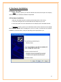
In Windows operating systems, the USB ADSL Modem will be detected and the “Found
New Hardware Wizard” will be displayed on the PC’s screen. Proceed with the software
installation in the next section, using the operating system appropriate to you.
9
5. Software Installation
The software installation procedures vary depending upon the operating system of your
PC. Be sure to follow the instructions provided for the operating system appropriate for you.
5.1 Before You Start…
The following information may be required for software installation. Contact your DSL
service provider before proceeding with software installation.
•
IP Address Settings – the software installation process allows the server to dynamically
assign IP Address settings. If your application requires static setting of specific address
information you will need to know:
IP Address
Subnet Mask (for Bridged Ethernet applications only)
Default Gateway (for Bridged Ethernet applications only)
•
Name Server Information – the software installation process allows the server to
dynamically assign Name Server Address settings. If your application requires static
setting of specific address information you will need to know:
Primary DNS Address
Secondary DNS Address
Primary WINS Address
Secondary WINS Address
•
Type of Driver to be installed – WAN and LAN software drivers are supported.
Note: Required if not using default value
•
ATM Virtual Path ID (VPI)
Note: Required if not using default value
•
ATM Virtual Circuit ID (VCI)
Note: Required if not using default value
•
Encapsulation type
Note: Required if not using default value
•
Modulation type
Note: Required if not using default value
•
User Name (for PPP applications only)
•
Password (for PPP applications only)
10
5.2 Windows Installation
The software setup process for Microsoft Windows applications (XP, 2000, Me, and
98SE) is described below with operating system specific differences noted. The USB ADSL
Modem should be connected to your PC prior to installing the driver software. No other
Windows programs should be running on your PC during the software install process
Step 1: The Microsoft Windows “Found New Hardware Wizard” will be displayed, click
“Cancel”.
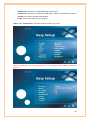
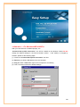
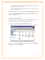
Step 2: Insert “ADSL MODEM Driver CD”, the front page of Easy Setup window will be
appeared,
11
Install Driver: Click here to install USB ADSL modem driver.
User Manual “Conexant AccessRunner USB ADSL”: Click here to read user’s manual.
Acrobat: Click here to install Acrobat Reader.
Panda: Click here to start Anti Virus program.
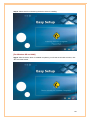
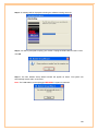
Step 3: Click “Install Driver”, and then select the country you are at,
PS. If your country is not on the list, please click “*” to next page. Select “Other”. Please see
page 17.
12
Step 4: After country selection, the window below will appear. Select the ISP, and then click
“``” to next page.
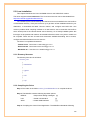
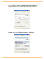
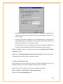
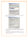
Step 5: Enter your account “User Name, Password and Password Confirm” then click “``”
to next page,
13
Step 6: Confirm modem settings and click “``” to next page,
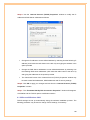
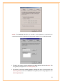
Step 7: Software kit searches available USB modem,
14
Step 8: Please wait for while during the device driver is installing.
[For Windows XP and 2000]
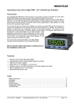
Step 9: After the device driver is installed completed, you will see the window as below, click
“X” to exit the wizard.
15
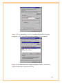
[For Windows ME]
Step 9: After the device driver is installed completed, you will see the window as below.
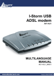
Step 10: Follow the previous appeared window, DSL Modem Setup Wizard will appear and
remind you the system will automatically reboot within 10 seconds.
Step 11: After reboot your system, please wait for DSL Modem Setup wizard complete the
device configuration process; then, your ADSL USB Modem will be installed properly.
16
[For Windows 98SE]
Step 9: For Widows 98SE, during the installation process, the system will ask you to insert
Windows 98SE installation CD, please insert the CD and click “OK”.
Step 10: Insert Windows 98SE CD-ROM in the selected driver and click OK.
Step 11: After the device driver is installed completely, you will see the window as below.
17
Step 12: Follow the previous appeared window, DSL Modem Setup Wizard will appear and
remind you the system will automatically reboot within 10 seconds.
Step 13: After system reboot, please wait for DSL Modem Setup wizard complete the device
configuration process and then your ADSL USB Modem will be installed properly.
Note: If your country ISP Setting is not in the ISP list,
If your country is not on the list, please click “*” to next page and select “Other”,
18
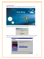
a) After you select ”Other”, the window below will appear,
PS. Please refer to the following table before you select “Typical Default WAN Setting” or
“Typical Default LAN Setting”.
Connection Type
WAN
LAN
Encapsulation and Multiplexing method
Network Information
PPP over ATM LLC (RFC 2364)
Internet Account information:
PPP over ATM NULL (RFC 2364)
z
User name
PPP over Ethernet (RFC 2516)
z
Password
Classical IP over ATM (RFC 1577)
TCP/IP information:
IP over ATM Bridged LLC (RFC 2684)
z
IP address
IP over ATM Bridged VC (RFC 2684)
z
Subnet mask
IP over ATM Routed LLC (RFC 2684)
z
DNS
IP over ATM Routed VC (RFC 2684)
z
Gateway
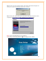
b) After connection type selection, the window below will appear, and then confirm
modem settings. All settings here are default, it might not correct settings for your
connection, double check settings for your ISP and go to “Accessing
Communication Settings on Windows” for the detail settings. (See Chapter 6)
19
<<Attention — For Windows ME & 98SE>>
After your device driver is installed properly, the
“Conexant Dial-up PPP Connection” icon will be created on the desktop. Please Do Not
change the default settings In the Phone Number section.
If the setting is changed by
accident, please do the following steps:
(1) Close the “Conexant Dial-up PPP Connection” tool first.
(2) Remove your ADSL USB Modem from the computer.
(3) Plug the ADSL USB Modem again to the computer for re-initialing.
(4) Then, the section will back to default settings.
20
5.3 Linux Installation
This chapter describes the Linux LAN/WAN driver for this USB ADSL modem.
This driver supports Linux-2.6 kernels. The Linux kernel sources can be downloaded from:
http://www.kernel.org/pub/linux/kernel/v2.6/.
The installed system should already have the kernel sources installed in the /usr/src/linux
or /lib/modules directory. If they are not there, try to get them off the installation disks for your
distribution, or download the latest Linux-2.6 kernel, and configure and build that. One
common problem while compiling modules on a new kernel is not to create link /usr/src/linux
which should point to the relevant kernel source directory. On a freshly installed system this
link might not be present and needs to be created before the kernel or any driver module can
be compiled. There are lots of books and documents available describing how to extract,
configure and build the kernel from it's sources...
The driver is compiled and tested for:
- Fedora Core 3 : kernel 2.6.9-1.667 using gcc 3.4.2
- SuseLinux 9.2 : kernel 2.6.8.8-24.10 using gcc 3.3.4
- Mandrake 10.1 : kernel 2.6.8.1-12mdk using gcc 3.4.1
5.3.1 Directory Structure
The directory Structure is as follows.
monaco_linux
|
|---ModemDrv
|
|---gpatm
|
|---Gti
|
|---cpl
5.3.2 Compiling the Driver
Step 1: Run make in the folder monaco_linux/ModemDrv/src to compile the driver.
Step 2: The Makefile contains following important options:
DEBUG
- Output driver debug messages [n]
LAN
- Create LAN interface
[y]
WAN
- Create WAN interfaces
[y]
Step 3: Compiling the Control Panel Application. The Makefile understands following
21
target(s).
% make
- This is to create the Control panel application.
(Command to be executed from directory monaco_linux/cpl.)
5.3.3 Loading Modem Driver
The module accepts several parameters that can be set when the module is loaded.
[Syntax]
insmod ./GUModem.ko {Module Options}
(Command to be executed from directory monaco_linux/ModemDrv/src)
[Module Options]
Rfc1483Mode
default: 0
(Bridged LLC)
Rfc1483VciX
default: 85+X
(X would be 1,2,3,4)
Rfc1483VpiX
default: X
(X would be 1,2,3,4)
Rfc2364Mode
default: 0
(VC)
Rfc2364VciX
default: X
(X would be 1,2,3,4)
Rfc2364VpiX
default: 116+X (X would be 1,2,3,4)
PVCCount
default: 4
(Maximum Ethernet interfaces)
PPPOACount
default: 4
(Maximum PPPOA Interfaces)
VPI and VCI settings to be used according to what's configured.
For example to load the module and to create 4 interfaces using different set of VCI/VPI
the command would be as follows:
% insmod ./GUModem.ko Rfc1483Mode=0 Rfc1483Vci1=35 Rfc1483Vpi1=0
Rfc1483Vci2=36 Rfc1483Vpi2=1 Rfc1483Vci3=37 Rfc1483Vpi3=2 Rfc1483Vci4=38
Rfc1483Vpi4=3 PVCCount=4 Rfc2364Mode=2 Rfc2364Vpi1=0 Rfc2364Vci1=116
Rfc2364Vpi2=0 Rfc2364Vci2=117
Issuing this command will create 4 ethernet interfaces and 2 PVC for PPPOA
interfaces. ( Combination of Rfc1483Vpi1 and Rfc1483Vci1 will be the first
interface, Rfc1483Vpi2 and Rfc1483Vci2 will be 2nd interface and so on.)
The details of various options used in command above is as below
1). PVCCount - This indicates the number of PVCs user wants to configure for ethernet
interfaces. Maximum value for this variable in this release is 4 and hence can have any
walue between 1 and 4, any value above 4 and below 1 is invalid and driver loading will
fail.
2). PPPOACount - This indicates the number of PVCs user wants to configure for
22
PPPOA interfaces. Maximum value for this variable in this release is 4 and hence can
have any walue between 1 and 4, any value above 4 and below 1 is invalid and driver
loading will fail.
3). Rfc1483Vpi1, Rfc1483Vpi2, Rfc1483Vpi3, Rfc1483Vpi4 -- These are 4 different
values of the VPIs that user wants to configure.
4). Rfc1483Vci1, Rfc1483Vci2, Rfc1483Vci3, Rfc1483Vci4 -- These are 4 different
values of the VCIs that user wants to configure.
5). Rfc1483Mode defines the mode for which the PVC is operating. In this release this
value of Rfc1483Mode remains same for all the PVCs which are being created. Thus all
VCs using rfc1483 encapsulation will be created using same encapsulation type.
6). Rfc2364Vpi1, Rfc2364Vpi2 -- These are different values of the VPIs that user wants
to configure for PPP interfaces.
7). Rfc2364Vci1, Rfc2364Vci2 -- These are different values of the VCIs that user wants
to configure for PPP interfaces corresponding to above mentioned VPIs.
Note: Please note that the VPIs/VCIs of the PVCs should not be conflicting with each other
else the driver loading will fail.
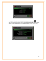
5.3.4 Verification of driver loading successfully
To determine if the driver has loaded:
% dmesg (or file /var/log/messages)
gp: USB Modem Driver Build
To determine if driver is in data mode.
% dmesg (or file /var/log/messages)
gp: Link established (8000/892)
^^^^ ^^^
^
^
^
Upstream rate
Downstream rate
Alternatively the control panel application can also be used to get Modem Status as given
below.
% gsi_cfg eth2 –s
( The ethernet device depends on what has been configured on the system )
(Command to be executed from monaco_linux/cpl)
23
6. Customizing Communication Settings
6.1 Accessing Communication Settings on Windows
Once the USB ADSL Modem and software have been installed, the communication
settings may be easily updated by performing the following steps:
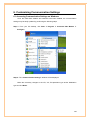
Step 1: From your PC desktop, click Start Æ Program Æ Conexant DSL Modem Æ
Configure.
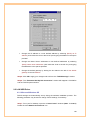
Step 2: The “Communication Settings” Window will be displayed.
Make the necessary changes to the VPI, VCI, Encapsulation type and/or Modulation
type and click Next>.
24
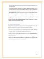
Step 3: The system must be rebooted to have the new settings take effect, therefore the
“Reboot” window will appear. Remove all disks from their drives, select Yes, reboot the
computer now, and click Close to reboot.
25
7. The DSL Status Application
The USB ADSL Status Application program provides a quick and easy way to check the
performance of the modem and the ADSL connection in Windows operating systems. When
open, the monitor window updates every 2 seconds.
7.1 Windows DSL Status Application
1. There are 3 methods to access the DSL Status Application:
z
From the Start Æ Programs Æ Conexant DSL Modem Æ DSL Status.
z
Form the PC desktop, double click the DSL Modem icon
z
From the PC desktop, double click the DSL Modem icon.
in the system tray.
Note: To access the DSL Status Application, the device driver must be running. Also,
make sure the USB cable is plugged into the modem.
2. The DSL Status Application allows you to review the current status of this ADSL
Modem and connection. The green indicator for LINK STATUS signifies that a
connection has been made. This indicator blinks while a connection is being established.
26
3. The system information can be displayed by clicking on the arrow button
.
This screen displays the release number of the Package Version, DSL Modem driver
version, Control Panel Version and the Firmware version you are currently using.
27
8. Software Uninstall
8.1 Windows Uninstall
Remove the USB ADSL Modem software drivers by performing the following steps:
Note: The USB cable should NOT be unplugged until you are prompted to do so.
Step 1: From your PC desktop, click Start Æ Programs Æ Conexant DSL Modem Æ
Uninstall.
Step 2: A message will be displayed and asking you to confirm the removal of the USB ADSL
modem software. Click Yes.
Step 3: You will be reminded not to unplug the USB cable until the uninstall process has been
completed. Click OK.
28
Step 4: A message will be displayed indicating the software is being removed.
Step 5: You will be prompted to unplug your modem. Unplug the USB cable from the PC and
click OK.
Step 6: The DSL Modem Setup Wizard window will appear as below. The system will
automatically reboot within 10 seconds.
Note: The USB cable must be unplugged BEFORE the system is rebooted.
29
9. Modifying TCP/IP Networking Option
9.1 WAN USB Driver
9.1.1 Microsoft Windows XP
TCP/IP settings are set up automatically during the software installation process. The
following procedure may be used to change TCP/IP settings, if necessary.
Step 1: From your PC desktop, open the “Control Panel” window
(Start Æ Control Panel). Double click the Network Connections icon.
Step 2: From the “Network Connections” window, right click the Conexant Dial-Up
PPP Connection icon and click Properties.
30
Step 3: The “General” tab of the “Conexant Dial-Up PPP Connection Properties”
window allows you to specify a different VPI and VCI, if needed. Contact your DSL
service provider before altering this connection information. Enter the VPI and VCI in the
Phone Number field (For example: 8,35)
Step 4: From the “Networking” tab of the “Conexant Dial-Up PPP Connection
Properties” Window, select Internet Protocol (TCP/IP) and click Properties.
31
Step 5: Use the “Internet Protocol (TCP/IP) Properties” window to modify the IP
address and DNS Server addresses as follows:
•
Change the IP address to a user defined address by selecting Use the following IP
address (click inside the radio button to the left of it) and typing the address in the
space provided
•
Change the DNS Server addresses to user defined addresses by selecting Use
the following DNS server addresses (click inside the radio button to the left of it)
and typing the addresses in the spaces provided.
•
The “Advanced” button of the “Internet Protocol (TCP/IP) Properties” window may
be used to alter DNS addresses, WINS addresses and IP security settings.
Step 6: Click OK to apply your changes and exit from the “Internet Protocol (TCP/IP)
Properties” window.
Step 7: The “Conexant Dial-Up PPP Connection Properties” window will reappear.
Click OK to end the TCP/IP options modification session
9.1.2 Microsoft Windows 2000
TCP/IP settings are set up automatically during the software installation process. The
following procedure may be used to change TCP/IP settings, if necessary.
32
Step 1: From your PC desktop, open the “Control Panel” window
(Start Æ Settings Æ Control Panel). Double click the Network and Dial-up icon.
Step 2: From the “Network and Dial-up” window, right click the Conexant Dial-Up
PPP Connection icon and click Properties.
Step 3: The “General” tab of the “Conexant Dial-Up PPP Connection Properties”
window allows you to specify a different VPI and VCI, if needed. Contact your DSL
service provider before altering this connection information. Enter the VPI and VCI in the
Phone Number field (For example: 8,35)
33
Step 4: From the “Networking” tab of the “Conexant Dial-Up PPP Connection
Properties” window, select Internet Protocol (TCP/IP) and click Properties
Step 5: Use the “Internet Protocol (TCP/IP) Properties” window to modify the IP
address and DNS Server addresses as follows:
34
•
Change the IP address to a user defined address by selecting Use the following IP
address (click inside the radio button to the left of it) and typing the address in the
space provided
•
Change the DNS Server addresses to user defined addresses by selecting Use
the following DNS server addresses (click inside the radio button to the left of it)
and typing the addresses in the spaces provided.
•
The “Advanced” button of the “Internet Protocol (TCP/IP) Properties” window may
be used to alter DNS addresses, WINS addresses and IP security settings.
Step 6: Click OK to apply your changes and exit from the “Internet Protocol (TCP/IP)
Properties” window.
Step 7: The “Conexant Dial-Up PPP Connection Properties” window will reappear.
Click OK to end the TCP/IP options modification session
9.1.3 Microsoft Windows ME
TCP/IP settings are set up automatically during the software installation process. The
following procedure may be used to change TCP/IP settings, if necessary.
Step 1: From your PC desktop, open the “Dial-up Networking” window
(Start Æ Settings Æ Control Panel Æ Dial-up Networking).
Double click the Dial-up Networking icon.
35
Step 2: From the “Dial-up Networking” window, right click the Conexant Dial-Up PPP
Connection icon and click Properties.
Step 3: From the “Networking” tab of the Conexant Dial-up PPP Connection
Window, select TCP/IP (marked with a check in the check-box to the left) and click
TCP/IP Settings button.
36
Step 4: Use the “TCP/IP Settings” window to modify the IP address, Name Server
address and/or default gateway as follows:
•
Change the IP address to a user defined address by selecting Specify an IP
address (click inside the circle to the left of it) and typing the address in the space
provided
•
Change the Name Server addresses to user defined addresses by selecting
37
Specify name server addresses (click inside the circle to the left of it) and typing
the addresses in the spaces provided
•
Change the default gateway by leaving the box blank to the left of Use default
gateway on remote network.
Step 5: Click OK to apply your changes and exit from the “TCP/IP Settings” window.
Step 6: The “Conexant Dial-Up PPP Connection” window will reappear. Click OK to
end the TCP/IP options session
9.1.4 Microsoft Windows 98SE
TCP/IP settings are set up automatically during the software installation process. The
following procedure may be used to change TCP/IP settings, if necessary.
Step 1: From your PC desktop, open the “Control Panel” window
(Start Æ Settings Æ Control Panel). Double click the Dial-up Connections icon.
Step 2: From the “Dial-up Connections” window, right click the Conexant Dial-Up
PPP Connection icon and click Properties.
38
Step 3: From the “Server Types” tab of the “Conexant Dial-up PPP Connection”
Window, select TCP/IP by checking the check to the left and click TCP/IP settings
button.
Step 4: Use the “TCP/IP Settings” window to modify the IP address, Name Server
address and/or default gateway as follows:
39
•
Change the IP address to a user defined address by selecting Specify an IP
address (click inside the circle to the left of it) and typing the address in the space
provided
•
Change the Name Server addresses to user defined addresses by selecting
Specify name server addresses (click inside the circle to the left of it) and typing
the addresses in the spaces provided
•
Change the default gateway by leaving the box blank to the left of Use default
gateway on remote network.
Step 5: Click OK to apply your changes and exit from the “TCP/IP Settings” window.
Step 6: The “Conexant Dial-Up PPP Connection” window will reappear. Click OK to
end the TCP/IP options session
9.2 LAN USB Driver
9.2.1 Microsoft Windows XP
TCP/IP settings are automatically set up during the software installation process. The
following procedure may be used to change TCP/IP settings, if necessary.
Step 1: From your PC desktop, open the “Control Panel” windows (Start Æ Control)
Double click the Network Connections icon.
40
Step 2: Double click the Local Area connection icon from the “Network
Connections” window.
Step 3: Select Internet Protocol (TCP/IP) from the “General” tab of the “Local Area
Connection Properties” windows. Click Properties.
Step 4: The “Internet Protocol(TCP/IP) Properties” window is used to modify the IP
address and DNS Server address as follows.
•
Change the IP address to a user defined address by selecting Use the following IP
41
address option (click inside the circle to the left of it) and typing the addresses in the
spaces provided
•
Change the DNS Server addresses to user defined addresses by selecting Use the
following DNS server addresses (click inside the circle to the left of it) and typing the
addresses in the spaces provided.
•
The Advanced button of the “Internet Protocol (TCP/IP) Properties” window may be
used to alter IP settings, DNS server addresses, WINS addresses, IP security options,
and TCP/IP filtering options.
Step 5: Click OK to apply your changes and exit from the “Internet Protocol (TCP/IP)
Properties”
Step 6: The “Local Area Connection Properties” window will reappear. Click OK to
end the TCP/IP options modification session.
9.2.2 Microsoft Windows 2000
TCP/IP settings are automatically set up during the software installation process. The
following procedure may be used to change TCP/IP settings, if necessary.
Step 1: From your PC desktop, open the “Control Panel” windows (Start Æ Settings
Æ Control). Double click the Network and Dial-up Connection icon.
Step 2: Double click the Local Area connection icon from the “Network and Dial-up
Connection” window.
Step 3: Select Internet Protocol (TCP/IP) from the “General” tab of the “Local Area
Connection Properties” windows. Click Properties.
42
Step 4: The “Internet Protocol(TCP/IP) Properties” window is used to modify the IP
address and DNS Server address as follows.
•
Change the IP address to a user defined address by selecting Use the following IP
address option (click inside the circle to the left of it) and typing the addresses in the
spaces provided
•
Change the DNS Server addresses to user defined addresses by selecting Use the
following DNS server addresses (click inside the circle to the left of it) and typing the
addresses in the spaces provided.
43
•
The Advanced button of the “Internet Protocol (TCP/IP) Properties” window may be
used to alter IP settings, DNS server addresses, WINS addresses, IP security options,
and TCP/IP filtering options.
Step 5: Click OK to apply your changes and exit from the “Internet Protocol (TCP/IP)
Properties”
Step 6: The “Local Area Connection Properties” window will reappear. Click OK to
end the TCP/IP options modification session.
9.2.3 Microsoft Windows ME
TCP/IP settings are automatically set up during the software installation process. The
following procedure may be used to change TCP/IP settings, if necessary.
Step 1: From your PC desktop, open the “Control Panel” windows (Start Æ Settings
Æ Control). Double click the Network icon.
Step 2: Select TCP/IP Æ Conexant USB ADSL LAN Modem from the
“Configuration” tab of the “Network” window. Click Properties.
Step 3: From the “IP Address” tab of the “TCP/IP Properties” window, select either
the Obtain an IP address Automatically or Specify an IP Address option, depending
on your network setup. If you select Specify an IP Address, type the IP Address and
Subnet Mask in the spaces provided. Consult with your network administrator to
determine which option best suit your individual needs.
44
Step 4: The “Gateway” tab allows you to add or remove gateways. Consult with your
network administrator to determine the appropriate address for your individual needs.
•
To add a new gateway, type the address in the New gateway field and click Add. The
new gateway will appear in the Installed gateway list.
•
To remove a previously installed gateway, highlight the entry to be removed in the
Installed gateway list and click Remove. The gateway will no longer appear in the
Installed gateways list.
45
Step 5: Click OK to apply your changes and exit from the “TCP/IP Properties”
windows.
Step 6: The “Network” window will reappear. Click OK to end the TCP/IP options
modification session.
Step 7: If you have made changes to TCP/IP properties, you will be asked to
restart/reboot your PC. Click Yes, and your PC will restart.
9.2.4 Microsoft Windows 98SE
TCP/IP settings are automatically set up during the software installation process. The
following procedure may be used to change TCP/IP settings, if necessary.
Step 1: From your PC desktop, open the “Control Panel” windows (Start Æ Settings
Æ Control). Double click the Network icon.
Step 2: Highlight TCP/IP Æ Conexant USB ADSL LAN Modem from the list of installed
network components in the “Configuration” tab of the “Network” window. Click
Properties.
Step 3: From the “IP Address” tab of the “TCP/IP Properties” window, select either
the Obtain an IP address Automatically or Specify an IP Address option, depending
on your network setup. If you select Specify an IP Address, type the IP Address and
Subnet Mask in the spaces provided. Consult with your network administrator to
determine which option best suit your individual needs.
Step 4: The “Gateway” tab allows you to add or remove gateways. Consult with your
network administrator to determine the appropriate address for your individual needs.
46
•
To add a new gateway, type the address in the New gateway field and click Add. The
new gateway will appear in the Installed gateway list.
•
To remove a previously installed gateway, highlight the entry to be removed in the
Installed gateway list and click Remove. The gateway will no longer appear in the
Installed gateways list.
Step 5: Click OK to apply your changes and exit from the “TCP/IP Properties”
windows.
Step 6: The “Network” window will reappear. Click OK to end the TCP/IP options
modification session.
Step 7: If you have made changes to TCP/IP properties, you will be asked to
restart/reboot your PC. Click Yes, and your PC will restart.
47
If you have any troubles to configure or setup this ADSL USB Modem, please contact us.
Before contacting us, make sure collect following information.
Submit complete detailed
information of your problem will help us to provide you accurate answers.
Model Name:
Serial Number:
PC Settings:
Other:
48