1
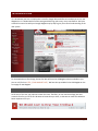
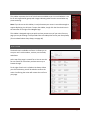
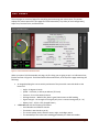
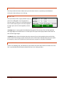
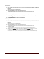
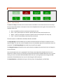
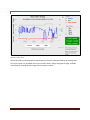
259 Dakota Ave South | PO Box 53 | Huron, SD 57350 | www.agsense.net | 605.352.8350 Page Last Updated: February 20, 2015 TABLE OF CONTENTS INTRODUCTION AVAILABILITY OF OLD WAGNET WE WOULD LIKE YOUR FEEDBACK 1 1 1 UNIT VIEWS LIST VIEW MAP VIEW SIDEBAR DETAIL VIEW 2 2 3 4 4 UNIT PAGES FIELD COMMANDER CROP LINK WEATHER TRAC (CROP LINK) GRAIN TRAC (CROP LINK) TANK MONITOR (CROP LINK) PUMP CONTROL (CROP LINK) SOIL MOISTURE MONITOR (CROP LINK) AQUA TRAC PRECISION LINK PIVOT POINT TRACKER 5 5 13 17 18 19 20 21 23 26 33 40 ACCOUNT MANAGEMENT ACCOUNT INFORMATION ACCOUNT SETTINGS CHANGE YOUR PASSWORD NOTIFICATION CONFIGURATION GROUP SETUP MY REPORTS 45 45 45 45 46 46 47 GETTING HELP KNOWLEDGE DATABASE INSTALLATION GUIDES CONTACT US 48 48 48 48 Table of Contents Page i INTRODUCTION It’s a brand new year here in 2013 and it is time for change! We would like to introduce you to our new WagNet site. It is loaded with all of the same good old things, plus many, many new features. We have created this manual to walk you through WagNet step by step to give you a sound understanding of the new system. AVAILABILITY OF OLD WAGNET For those who do not like change, do not fret! We still have the old WagNet website available to you. You can still find it at HTTP://OLD.WAGNET.NET/. We have also provided a link to old WagNet on the front page of new WagNet. WE WOULD LIKE YOUR FEEDBACK As the user of this site, your opinions matter the most. Therefore, on our new Home Page, we have created a form for you to fill out. We want to know what you think, so that we can make this website a better experience for you. Introduction Page 1 UNIT VIEWS Our new WagNet site includes four unit views: List View, Map View, Detail View, and the familiar sidebar. Each of these views was available on our old WagNet site, but has been drastically improved for our new site. List View and Map View can each be located in the View Units menu option at the top of the page. LIST VIEW The List View page displays a summary of each of your units as a series of dynamic images designed to load the information for each of your units. The information loaded depends on the type of unit being displayed: Pivot units of various types (Field Commanders, Pivot Points, and Precision Links) display a graphic representation of the pivot, the power status, current direction, current angle, current speed, current pressure, current tables, and latest reading time. Crop Links display the latest reading information about the various sensors installed on them and the latest reading time. Tank Monitors display a graphic gauge indicating its current liquid level. Aqua Tracs display soil moisture data and the latest reading time. Figure 1 - List View The List View of one of our administrators Clicking on a unit will open that unit’s page. See page 5 for more information on the unit control panels. The units are also organized based on your current group configuration. See page 46 for more information about group setup. The group names in the group header bars can be clicked to open the map view for that group. Units can also be organized within the same group by dragging the units to a different spot in the group or to a new group by dragging the unit to that group. Groups can also be organized by dragging the group header bar. If your group contains pivots, the group header will have a have start and stop buttons for all the pivots that are stopped or running, respectively. Unit Views Page 2 MAP VIEW Figure 2 - Map View Figure 2 - Map ViewError! Reference source not found. shows a group of pivots on an AgSense page. The map in the center shows all the units in the currently selected group. Pivots displayed on the map will show their current status, angle, direction, and pressure. Around the outside of the pivots are lines that represent the “end gun on” and field info sections. Crop Links will appear on the map with various icons based on the type of data it is configured to provide. Aqua Tracs show up as a rain drop icon. Tank monitors, whether Crop Link or Aqua Trac, will show a gauge indicating their current tank level. In the top-right corner of the map are three map controls: Zoom to Selected Unit, Show Group, and Follow Me. The Zoom to Selected Unit button will zoom in as far as necessary to selected unit. The Show Group button will zoom and pan the map to show the entire group. The Follow Me button works with devices that have location services such as smart phones and, possibly, tablets. This button will put a marker on the map indicating your current location and frequently update its location and follow it on the map. This is particularly useful if you are driving around in the fields and would like to know the current status of your units in the area. The section on the right side of the page shows a summary of the currently selected unit’s latest reading information. For pivots, a few basic start, stop, and direction command buttons have been provided for quick interaction with your pivots. Unit Views Page 3 SIDEBAR This sidebar represents the list of units that was available to you in our old website. It is a list of units organized by groups with images indicating what the units are and what any pivots are doing. Note: If you do not see this sidebar, it may be because your screen is not wide enough to support displaying it at all times. To open the sidebar, simply click the View Units item in the menu bar to the right of the WagNet logo. This sidebar is designed to give you quick and easy access to any of your units from any page you may be viewing. It also provides links to the Map View and to your Group Setup (for more detail about Group Setup, see page 46). Figure 3 - Sidebar DETAIL VIEW The detail view is available to all users. It allows you to see your unit’s serial numbers, versions, service levels, and aliases. At the top of the page is a search form. You can use this form to search for units when you have too many to browse through. To the right of each unit is a Delete Unit button. When you click this button, you will be asked to confirm the action. Confirming the action will remove the unit from your page. Unit Views Page 4 UNIT PAGES The unit pages are a series of pages for controlling and monitoring your various units. This section explains the various parts of the unit pages for Field Commanders, Crop Links (of each configuration), Aqua Tracs, Precision Links, and Pivot Points. FIELD COMMANDER Figure 4 - Field Commander Information Panel When you open a Field Commander unit page, the first thing you are going to see is an information box, like the one seen in Figure 4 - Field Commander Information Panel, at the top of the page containing the following: An image displaying the current activity and status of the pivot with numerical details at the bottom of: o Angle – 0 degrees is North o Speed – in Percent, or Inches per Minute (TL Pivots) o Pressure – the current water pressure o GPS signal status – WAAS is best, Basic is good, None means no GPS reading o Signal strength – the strength of the signal your pivot is communicating with (0 – 31) o Battery level – 4.2V is a fully charged battery A Pivot Info tab with the following information: o Serial Number and Software Version o If and who it was shared to you by o The current power status, direction status, angle, and endgun status o The timestamp of the most recent reading generated by the Field Commander Unit Pages Page 5 o The amount of time the Field Commander has been on its current cycle o The most recent 2 commands sent to the Field Commander o Upcoming timed commands – and a button to clear all timed commands o Currently active commands o Complete Revolution Time and Remaining Revolution Time o The most recent note entered in the notes tab o Up-to-date precipitation and evaporation info (if sensors are installed/configured) A Timed Commands tab listing all currently set timed commands A Notes tab where you can enter various notes about the unit or field Below the information panel is a series of tabbed panels: CMD, Chart, Config, Field Info, Forms, Readings, Report, CMD History, Unit History. The CMD tab displays various command controls you can use to control your Field Commander unit including Start/Stop/Change Direction commands, Endgun/Speed table controls, and Run table controls. UNIT PAGE SETUP Units of all types have a link below the information box to provide the unit owners some additional control over their unit pages. By “unit owners” we mean that if the unit has only been shared with you and not entirely moved to your page, you will not see this link. This ensures that only the unit owner will be able to change this configuration. Figure 5 - Unit Page Setup Link Different types of units (Crop Links, Field Commanders, etc.) will have different configuration options in this box. Field Commanders have options for changing what their End gun and Speed tables are called. This does not mean the alias of each table configuration, but rather the red title text “End Gun” and “Speed” above the table selection dropdowns. Another configuration option that every unit type (except Aqua Trac) has is the ability to control whether or not your dealer will have access to send commands to your unit. Unchecking this option will ensure that your dealer will not be able to send commands like “Start” and “Stop” to your unit. However, dealers will still have access to change and save the unit’s configuration in the Config tab. Unit Pages Page 6 CMD TAB Figure 6 – Basic Field Commander Commands The Start and Stop commands can be used to send an immediate or timed command to start and stop the unit respectively based on the option chosen in the dropdown box to the right of the command. The available options are: Now – Immediately sends a start/stop command to the unit Once – Gives you the option to choose a specific date and time to start/stop the unit Always – Gives you the option to choose a specific time to start/stop the unit every day Clear – Clears all once/always timed start/stop commands The Start FWD and Start REV commands allow you to send an immediate start command to start the pivot in the direction of your choice. The Stop @ Angle command allows you to send a timed command to the Field Commander to stop the unit at a specified angle. You can also use the dropdown box to the immediate right of the command to clear the command. The Dual Stop @ Angle command lets you specify two angles. The Change Direction commands can be used to send an immediate command to the unit to change its current direction. Also note that when the unit is powered off, all of these commands will be disabled until the unit is powered on. When the unit is on and idle, the stop commands will be disabled. When the unit is on and moving, the start commands will be disabled. When the unit is moving forward, the Change Dir FWD command will be disabled and vice versa for the Change Dir REV command. The End Gun table allows you to adjust the angles at which the end gun on your pivot will run. There are three customizable tables that can be renamed and two tables called Always On and Always Off. In the customizable tables, once you have entered your preferred settings click Save & Send command to lock in those settings. Also click this command to lock in tables when switching between them. The Speed Table is divided into 4 separate types: Panel Speed, Unit Pages Page 7 Flat Rate, Simple Table, and VRI Table. In all, but the Panel Speed option, you have the ability to choose the duty cycle at various angles of the field. We have also added an Inches Applied column so that you can adjust your speed tables by how many inches of water you want the Field Commander to apply to each section of field. The table will then automatically update the speed required to match that value based on the configuration in the Config tab. Pivot length, estimated flow, and run time at 100% (hours it takes to do a full revolution at max speed) must be entered and as accurate as possible for this feature to work correctly. This column can also be displayed in metric units (centimeters) by selecting the unit system from the dropdown box below the table name dropdown box. This unit system selection will be automatic for users who have set their preferred unit measuring system in their Account Settings page (see page 45 for details). Another new feature of the speed table is the ability to adjust the entire table’s Speed column by a percentage of its current value. For example, if you had a setting set to 40% duty cycle, raising it by 5% would increase it to 42 (which is an increase of 5% of 40). Also if you change the values of your Speed Table, but decide that you do not like the changes, you can click the Reset Speed Table button to reset the table to its original values. CHART TAB Figure 7 - Field Commander Chart This tab provides you with a graphical representation of historical data provided by the readings sent from your Field Commander unit. Available chart series include Pressure, Angle, Signal Strength, and Battery. Available time frames for viewing this data range from one day to a month. Other data series may appear if additional sensors are configured/installed. Unit Pages Page 8 CONFIG TAB The Config tab allows you configure your unit to ensure accurate data readings. Please note that inaccurate configuration could result in inaccurate readings. The following steps will walk you through the configuration of your Field Commander. 1. Enter the name of your unit. What you enter here will be the name that shows up describing the unit throughout the WagNet site. A descriptive name about its location is best (ex. ‘Behind Barn’) to know at all times exactly which unit you are looking at. Enter the type of pivot the Field Commander box is installed on. 3. Selection which direction the pivot runs. 2. If your unit runs in a circle, then this option should be set as such. A pivot that runs side to side is called a lateral pivot and you should choose which direction the pivot runs. 4. Enter the length of the pivot in feet. This number is used in several calculations involved in Speed Tables and reading generation; so, please make sure this number is as accurate as you can get it. 5. Enter the distance your pivot’s end gun reaches 6. (For circle pivots) Enter the minimum angle of the unit’s operation Remember that 0 degrees represents straight North. This number is used in several calculations involved in Speed Tables and reading generation; so, please make sure this number is as accurate as you can get it. 7. (For circle pivots) Enter the maximum angle of the unit’s operation Remember that 0 degrees represents straight North. This number is used in several calculations involved in Speed Tables and reading generation; so, please make sure this number is as accurate as you can get it. 8. Enter the time it takes for the pivot to complete one revolution at 100% duty cycle (speed). This number is used in several calculations involved in Speed Tables and reading generation; so, please make sure this number is as accurate as you can get it. 9. Enter the type of pressure sensor being used. 200 PSI is our normal 10. Enter the low pressure setpoint. If the pressure falls below this amount, the unit will send a reading right away instead of waiting till the next normal reading time. 11. Enter the high pressure setpoint. If the pressure rises above this amount, the unit will send a reading right away instead of waiting till the next normal reading time. 12. Enter the pressure sensor voltage at 0 PSI 0.5 volts is the correct normal value. 13. Enter the estimated flow in gallons per minute This number is used in several calculations involved in Speed Tables and reading generation; so, please make sure this number is as accurate as you can get it. 14. The External 1 and External 2 fields are set by AgSense only when you have a Rain Bucket, call 1605-352-8350 for details. 15. Enter the conditions for speed and end gun usage. 16. Click Save Settings and then proceed to the instructions below to set your pivot’s GPS location. Unit Pages Page 9 Now that you have your Field Commander configured to the correct settings, the next step is to set the GPS location on the map at the bottom of the Config tab. For circle pivots: 1. The GPS coordinates should automatically fill in once the unit has been installed and the pivot has been run. If this does not occur, or if you wish to manually enter the center point of the pivot, enter the GPS coordinates of the center of your pivot in the text boxes provided for latitude and longitude. Coordinates must be entered in decimal degrees. 2. If you wish to adjust the zoom setting, feel free to do so. This setting adjusts the zoom level for the map image in the information panel at the top of the page. 3. Click Center on Map. A marker should appear on the map 4. In the map provided, if the marker is not exactly over the center location of your pivot, you can fix it by clicking on the map where the center should be. 5. Click Save Settings again to save the GPS coordinates. For lateral pivots: 1. The GPS coordinates should automatically fill in once the unit has been installed and the pivot has been run. If this does not occur, or if you wish to manually enter the location of the pivot, enter the GPS coordinates of your pivot in the text boxes provided for latitude and longitude. Coordinates must be entered in decimal degrees. 2. If you wish to adjust the zoom setting, feel free to do so. This setting adjusts the zoom level for the map image in the information panel at the top of the page. 3. Click Center on Map. This will position the map to where your pivot is. Unlike a circle pivot a marker will not appear on the map. 4. Starting in the Northwest corner of the pivot area and going clockwise in each of its corners, click on the map to mark the four corners of your lateral pivot’s operation area. Once the fourth marker is placed, the configuration will automatically save and refresh the unit page. FIELD INFO TAB This tab has 4 sections. Field Observations and Pivot Service Records allow you to enter specific types of notes and download them as a CSV file. Field Description by Angle allows you to describe separate sections of the field. By selecting a color, a line will appear around the edges of your pivot image at the top of the page once you have saved. Field Info is a form where you can enter information about the Well, Land Description, Owner, Operator, and Water District. Unit Pages Page 10 FORMS TAB The forms tab currently provides four forms (more may have been added since the last manual update): a pre-start checklist, an annual pre-season electrical safeguard inspection checklist, a utility information form, and a well info log. Once saved, the saved form information can be viewed and printed from the box below the form. READINGS TAB This tab provides the historical data sent by the Field Commander unit. It provides you with detailed information about what your unit is doing. This information is particularly useful for locating the source of and time at which any problems that may arise. REPORT TAB The report tab provides a highly detailed report of your unit’s reading data. You can generate or print three types of reports for a specified period of time. The three report types are an event report, an inches applied by angle report, or an inches applied by month report. An Event report displays tabular information about the change in the Field Commander’s power, direction, status, and pump status and the duration of those periods of activity. A Readings report is a downloadable Microsoft Excel spreadsheet of the reading data for the period of time specified. If you do not own Microsoft Excel, you may use Google Drive, Microsoft OneDrive, or Open Office to view the spreadsheets for free. A By Angle report is more graphical and displays two graphs of the amount of acre inches applied to each angle degree of the pivot area in a circular pivot. The report also displays tabular information for each of those angle ranges. A By Month report shows information about the amount of acre inches applied to the entire field by month. Note that entering in partial months will result in information returned about the entire month. For example, a report for 1/15/2013 to 2/15/13 will result a report for 1/1/2013 to 2/28/2013. CMD HISTORY TAB Similar to the Readings tab, the CMD History tab provides the information about commands sent to the unit. It provides detailed information about what your unit is doing and why. The top section displays all currently active commands. Unit Pages Page 11 UNIT HISTORY TAB The unit history tab show all changes made to the unit including configuration and service level changes and any notes from support calls provided by our service representatives. Unit Pages Page 12 CROP LINK Because there are many configurations for Crop Links, the Crop Link unit page’s appearance will vary from configuration to configuration. The following five sections: Weather Trac, Grain Trac, Tank Monitor, Pump Control, and Soil Moisture Monitor explain the various differences those types of Crop Links have in their unit pages. The rest of this section will discuss all parts of the unit page that all Crop Links share. CHART In most Crop Link unit pages, the chart is at the top of the page. However, in Tank Monitors and Weather Tracs, the chart is in a tab and is replaced by a series of graphics illustrating the latest reading information from the Crop Link. The icon to the top right of the chart will allow you to print it. Figure 8 - Crop Link Chart Unit Pages Page 13 UNIT PAGE SETUP Units of all types have a link below the information box to provide the unit owners some additional control over their unit pages. By “unit owners” we mean that if the unit has only been shared with you and not entirely moved to your page, you will not see this link. This ensures that only the unit owner will be able to change this configuration. Different types of units (Crop Links, Field Commanders, etc.) Figure 9 - Unit Page Setup Link will have different configuration options in this box. Since Crop Links have a gauges display for their analog and digital sensors, we have provided you the ability to turn those gauges on or off. Another configuration option that every unit type (except Aqua Trac) has is the ability to control whether or not your dealer will have access to send commands to your unit. Unchecking this option will ensure that your dealer will not be able to send commands like “Relay On” and “Relay Off” to your unit. However, dealers will still have access to change and save the unit’s configuration in the Config tab. MAIN TAB The Main tab is the tab that displays all information about the Crop Link’s current status, its most recent reading information, and its commands. Each Crop Link can have two relays. When relays are enabled in the Config tab (see page 15), one or two buttons will appear on the Main tab that allow you to turn the relays on and off. Additional information will be displayed here for other types of Crop Links. Unit Pages Page 14 CONFIG TAB The Config tab is how you configure a Crop Link to be whatever type of Crop Link you want it to be. This guide will walk you through step by step how to set up each part of the configuration that is not related to those options, but for generic Crop Links. Configuration instructions for each type of Crop Link other than generic types will be given in their corresponding sections. 1. Enter the Name of your unit. What you enter here will be the name that shows up describing the unit throughout the WagNet site. A descriptive name is best (ex. ‘Outdoor Tank’) to know at all times exactly which unit you are looking at. 2. FC Link – An advanced config option, typically only set by AgSense to link the crop link to a field commander to enable automatic pump control, etc. 3. Soil Moisture Type – If a soil moisture sensor is being used, choose the type you are using here. 4. Grain Bin Board – If a Grain Trac board/s is being used, choose and configure it here 5. Analog – If any analog sensors are being used, choose them from the drop down menus that correspond to the crop link board terminals that the sensors are wired into (AN 1-6) 6. Digital – If any digital sensors are being used, choose them from the drop down menus that correspond to the crop link board terminals that the sensors are wired into (INT1-3) 7. If you will be using the relays, set the Relays field to Enabled. A few more options will appear to configure the relays. The following sub-instructions will walk you through configuring them. a. Enter a name for relay 1 This step is optional. If blank, the relay name will default to ‘Relay 1.’ b. Check Momentary if the relay is to operate momentary Quick pulses on/off c. Leave Momentary unchecked if the relay is to operate continuously Stays on/off d. If the unit will be communicating to a Field Commander, check the Continuous box to have the pair of units in constant communication with each other, continuously sending the commands for the relays to be on/off. e. Check Disable if you do not wish to use the relay. f. Repeat steps a-d for Relay 2. 8. VFD – If this crop link will be used to control a VFD (variable frequency drive) using the 0-10v output of the crop link, choose Enable from the drop down, and then set the min/max Hertz that your VFD is setup for in the Volts vs Hertz 0v and 10v boxes Example: some are set up to do 0-60Hz, some are set up for 30-90Hz 9. Click Save Settings. READINGS TAB This tab provides the historical data sent by the Crop Link unit. It provides you with detailed information about what your unit is doing. Unit Pages Page 15 REPORT TAB The Report tab gives you a summarized table of information from the readings for a specified date range that you can generate or print. NOTES TAB This tab allows you to enter notes to yourself about a unit or field. It will automatically be time stamped. UNIT HISTORY TAB The unit history tab show all changes made to the unit including configuration and service level changes and any notes from support calls provided by our service representatives. Unit Pages Page 16 WEATHER TRAC (CROP LINK) CHART In most Crop Link unit pages, the chart is at the top of the page. However, in Tank Monitors and Weather Tracs, the chart is in a tab and is replaced by a series of graphics illustrating the latest reading information from the Crop Link. When your Weather Trac (Crop Link) unit page loads, you’ll notice that the top of the page is no longer a chart, but rather a series of gauges displaying the latest reading data graphically. In old WagNet, this information was given to you as text in the Main tab; however, in our new WagNet site we have upgraded this to a graphic display as shown in Figure 11 - Weather Trac Reading Display. Figure 11 - Weather Trac Reading Display In this type of Crop Link, the chart has been moved to a tab below the gauges. The chart has additional series for the historical data represented by each of the gauges in the top panel. For example, in Figure 10 - Weather Trac Chart, you’ll notice that the series of this chart include: humidity, wind direction, temperature, wind speed, wind gust, rain, battery and power. Normally these names are abbreviated to indicate what type of sensor they represent. In this figure, they are from each sensor’s alias configuration. In New Wagnet, you will Figure 10 - Weather Trac Chart have the ability to name each sensor or leave it with the default abbreviated sensor type. Unit Pages Page 17 GRAIN TRAC (CROP LINK) Grain Tracs (Crop Links) are displayed somewhat differently in WagNet. When a single unit is configured for multiple grain bins, each will be displayed as a separate unit. The unit page for each bin displays information for each individual unit. For information on how to configure a Grain Trac (Crop Link) for multiple bins, see page 18. MAIN TAB The Main tab is the tab that displays all information about the Crop Link’s current status and its commands. All Crop Links have a Get Reading command which requests a reading from the Crop Link unit. Each Crop Link can have two relays. When relays are enabled in the Config tab (see page 14), two commands will appear on the Main tab that allow you to turn the relays on and off. The Main tab in a Grain Trac (Crop Link) unit page will also contain the chart of readings from the unit’s sensors and cables as shown in Figure 12 - Grain Trac Data. Figure 12 - Grain Trac Data CONFIG TAB Figure 13 – Grain Bin Board Configuration 1. The configuration of the grain bin units is done on a per-cable basis. What that means, is that each line of the configuration is 1 temp cable a. Bin Num = What bin that cable is installed into Starting with 1 and up for each additional bin b. Cable Num = What cable number it is within the bin c. Board Number = The address of the grain trac board that the cable is being installed into d. Start Sensors = The terminal number location on the grain trac board where this cables’ sensors start at e. Num Sensors = The number of sensors that this cable contains 2. After each line of the configuration is entered, a new line will appear below it. 3. Repeat filling in each of the boxes (1a-1e above) for each additional cable. 4. To save the configuration, click on Save Settings If your configuration includes multiple bins, they will show up as separate units after saving the configuration and refreshing your page – you can then go to each of the separate bins’ pages , click on config, and enter in a new name for that bin and then click save settings. Unit Pages Page 18 TANK MONITOR (CROP LINK) Tank Monitors (Crop Links/Aqua Tracs) are displayed somewhat differently in WagNet. When a single unit is configured for multiple tanks, each will be displayed as a separate unit. The unit page for each tank displays information for each individual unit. CHART In most Crop Link/Aqua Trac unit pages, the chart is at the top of the page. However, in Tank Monitors, Soil Moisture Monitors, and Weather Tracs, the chart is in a tab and is replaced by a series of graphics illustrating the latest reading information from the Crop Link. When your Tank Monitor unit page loads, you’ll notice that the top of the page is no longer a chart, but rather a series of gauges displaying the latest reading data graphically. In old WagNet, this information was given to you as text in the Main tab; however, in our new WagNet site we have upgraded this to a graphic display as shown in Figure 15 - Tank Monitor Reading Display. Figure 15 - Tank Monitor Reading Display In this type of Crop Link/Aqua Trac, the chart has been moved to a tab below the gauges. The chart has additional series for the historical data represented by each of the gauges in the top panel. For example, in Figure 14 - Tank Monitor Chart, you’ll notice that the series of this chart include: Tank Monitor1. These names represent the type of sensor on the Crop Link/Aqua Trac. Unit Pages Figure 14 - Tank Monitor Chart Page 19 CONFIG TAB Figure 16 - Example Tank Monitor Configuration 1. On Crop Links, If Analog is set to Disabled, set it to Enabled. 2. On Crop Links, Set the corresponding Analog # setting to Tank Monitor. 3. On Aqua Tracs, set each of the Watermark/Tank Monitor dropdowns to Tank Monitor for each sensor you are using. A series of fields should appear. 4. Fill out the Analog # Options fields as accurately as you can. 5. Repeat steps 2 and 3 for all connected Tank Monitoring sensors. 6. Click Save Settings. PUMP CONTROL (CROP LINK) CONFIG TAB In pump control units, there are two areas of the config that are important: FC Link and Relays. The FC Link field gives you access to the pump control settings from a Remote Pump Control button in the linked pivot unit. Up to 5 pivot units can be Figure 17 - FC Link linked to a single pump control. It is an advanced option typically only set by AgSense. Figure 18 - Relays 1. To set up a pump control, set Relays to Enabled if you have not already done so. 2. Then follow the instructions for configuring relays on page 15. Unit Pages Page 20 SOIL MOISTURE MONITOR (CROP LINK) CHART In most Crop Link unit pages, the chart is at the top of the page. However, in Tank Monitors, Soil Moisture Monitors, and Weather Tracs, the chart is in a tab and is replaced by a series of graphics illustrating the latest reading information from the Crop Link. When your Soil Moisture unit page loads, you’ll notice that the top of the page is no longer a chart, but rather a series of gauges displaying the latest reading data graphically. In old WagNet, this information was given to you as text in the Main tab; however, in our new WagNet site we have upgraded this to a graphic display as shown in Figure 19 - Soil Moisture Reading Display. Figure 19 - Soil Moisture Reading Display In this type of Crop Link, the chart has been moved to a tab below the gauges. The chart has additional series for the historical data represented by each of the gauges in the top panel. For example, in Figure 20 – Soil Moisture Chart, you’ll notice that the series of this chart include: S1, S2, … S6, and Sum. These names represent the type of sensor on the Crop Link and the sum lines specified in the configuration. Figure 20 – Soil Moisture Chart Unit Pages Page 21 MAIN TAB In addition to the other crop link features included in the Main tab, it also displays reading data from the linked soil moisture probe and its sensors. CONFIG TAB To configure a soil moisture monitoring unit: 1. Set Soil Moisture Type to the type of soil moisture probe being used. A series of new configuration fields will appear. 2. Set the Soil Type of the soil the sensor is measuring. 3. Set the Probe Id field to the serial number of the probe to link with 4. Set the depths in inches of the 1-6 Figure 21 - Soil Moisture Config sensors of your probe. 5. Set the Full line and Refill line for the graph. Unit Pages Page 22 AQUA TRAC CHART In Aqua Tracs, the chart is located at the top of the page. Aqua Trac charts have a lot of chart series including: probe sensor data, watermark data, temperature data, rain data, and sum. Figure 22 - Aqua Trac Chart Our Aqua Trac charts allow you to choose what data is displayed, what period of time is charted, and any additional options to fit the chart to your needs. Unit Pages Page 23 MAIN TAB The Main tab displays all the latest reading and command information from the Aqua Trac unit. The WM# information is the latest reading for the watermark sensors. Soil moisture probes provide various different types of information. The ones in this image shows moisture and temperature reading information. Figure 23 - Aqua Trac Reading Data Aqua Tracs with watermark sensors now provide water depletion calculations based on formulas provided to us by the University of Nebraska. This will display the average centibar reading for each foot of soil, the depleted readily available water, and the remaining readily available water. CONFIG TAB If using a soil moisture probe: a. Select the type of probe you are using from the Soil Probe Type dropdown list. b. Enter the probe ID and sensor depths if you have them (probe ID is mandatory for Aquacheck probes) c. Enter the Full Line and Refill Line for the graph if you know them (usually determined by an agronomist) d. Click Save Config at the bottom of the page. If using watermark sensors: a. Select the Watermark soil type to enable the Watermark Sensor Reading Water Depletion Calculations as shown in the figure above. b. Select the type of watermark you are using from the dropdowns for analog sensors 1-4 and the sensor depth for each one. c. Click Save Config at the bottom of the page. If using Tank Monitor Sensors: a. Select Tank Monitor from the dropdowns for sensor 1-2. b. Enter the Specific Gravity of the liquid that is in the tank. c. Enter the tank diameter Unit Pages Page 24 d. Enter the tank height e. Enter the distance from the bottom of the tank to the Tank Monitor Sensor. f. Click Save Config at the bottom of the page. If using a Temperature sensor, select Thermistor from the Sensor 5 dropdown, and click Save Config at the bottom of the page. If using a Rain Tipping Bucket, select Tipping Bucket from the Tipping Bucket 1 dropdown, and click Save Config at the bottom of the page READINGS TAB This tab provides the historical data sent by the Aqua Trac unit. It provides you with detailed information about what your unit is doing. NOTES TAB This tab allows you to enter notes to yourself about a unit. It will automatically be time stamped. Unit Pages Page 25 PRECISION LINK Figure 24 - Precision Link Information Panel When you open the unit page, the first thing you are going to see is an information panel, like the one seen in Figure 24 - Precision Link Information Panel, at the top of the page containing the following: An image displaying the current activity and status of the pivot with numerical details at the bottom of: o Direction – FWD/REV o Rate – in inches o Angle – 0 degrees is straight North o Speed – in ipm o Pressure – in pounds per square inch o GPS signal status – WAAS is best, Basic is okay, None means no GPS reading o Signal strength – the strength of the signal your pivot is communicating with (0 – 31) o Battery level – 4.2V is a fully charged battery A Pivot Info tab with the following information: o If and who it was shared to you by o The current power status, direction status, angle, and endgun status o The timestamp of the most recent reading generated by the Pivot Point o Information about the most recent 2 commands sent to the Pivot Point o Information about upcoming timed commands o The most recent note entered in the notes tab o A list of urrently active commands A Timed Commands tab listing all currently set timed commands A Notes tab where you can enter various notes to yourself about the unit Unit Pages Page 26 Below the information panel is a series of tabbed panels: CMD, Chart, Config, Readings, Report, CMD History, Tickets, and PPC III. The CMD tab displays various command controls you can use to control your Pivot Point unit including Start/Stop/Change Direction commands, Endgun/Rev Aux table controls, and the ability to request a reading. UNIT PAGE SETUP Units of all types have a link below the information box to provide the unit owners some additional control over their unit pages. By “unit owners” we mean that if the unit has only been shared with you and not entirely moved to your page, you will not see this link. This ensures that only the unit owner will be able to change this configuration. Figure 25 - Unit Page Setup Link Different types of units (Crop Links, Field Commanders, etc.) will have different configuration options in this box. Precision Links, however, do not have any special options other than the following one. A configuration option that every unit type (except Aqua Trac) has is the ability to control whether or not your dealer will have access to send commands to your unit. Unchecking this option will ensure that your dealer will not be able to send commands like “Start” and “Stop” to your unit. However, dealers will still have access to change and save the unit’s configuration in the Config tab. Unit Pages Page 27 CMD TAB The Start and Stop commands can be used to send an immediate or timed command to start and stop the unit respectively based on the option chosen in the dropdown box to the right of the command. The available options are: Now – Immediately sends a start/stop command to the unit Once – Gives you the option to choose a specific date and time to start/stop the unit Always – Gives you the option to choose a specific time to start/stop the unit every day Clear – Clears all once/always timed start/stop commands In Precision Links, the Start command gives you the option to start the unit in either direction running either wet or dry. The Stop @ Angle command allows you to send a timed command to the Pivot Point to stop the unit at a specified angle. You can also use the dropdown box to the immediate right of the command to clear the timed command. The Change Dir FWD and Change Dir REV commands can be used to send an immediate command to the unit to change its current direction. The Change Application and AUTO STOP/REV are special commands only available in the Precision Link unit. Figure 26 - Precision Link Special Commands Unit Pages Page 28 Figure 27 - Precision Link Tables and Get Reading Commands The End Gun table allows you to adjust the angles at which the end gun on your pivot will run. There are three customizable tables that can be renamed and two tables called Always On and Always Off. In the customizable tables, once you have entered your preferred settings click Save & Send command to lock in those settings. Also click this command to lock in tables when switching between them. Unit Pages Page 29 CHART Figure 28 - Precision Link Chart This tab provides you with a graphical representation of historical data provided by the readings sent from your Precision Link unit. Available chart series include Pressure, Angle, Signal Strength, and Battery. Available time frames for viewing this data range from one day to a month. CONFIG 1. Enter the name of your unit. What you enter here will be the name that shows up describing the unit throughout the WagNet site. A descriptive name about its location is best (ex. ‘Behind Barn’) to know at all times exactly which unit you are looking at. 2. Selection which direction the pivot runs. If your unit runs in a circle, then this option should be set as such. A pivot that runs side to side is called a lateral pivot and you should choose which direction the pivot runs. 3. Enter the length of the pivot in feet. This number is used in several calculations involved in Speed Tables and reading generation; so, please make sure this number is as accurate as you can get it. 4. Enter the distance your pivot’s end gun reaches This number is used in several calculations involved in Speed Tables and reading generation; so, please make sure this number is as accurate as you can get it. 5. (For circle pivots) Enter the minimum angle of the unit’s operation Remember that 0 degrees represents straight North. This number is used in several calculations involved in Speed Tables and reading generation; so, please make sure this number is as accurate as you can get it. 6. (For circle pivots) Enter the maximum angle of the unit’s operation Remember that 0 degrees represents straight North. This number is used in several calculations involved in Speed Tables and reading generation; so, please make sure this number is as accurate as you can get it. Unit Pages Page 30 7. Enter the time it takes for the pivot to complete one revolution at 100% duty cycle (speed). This number is used in several calculations involved in Speed Tables and reading generation; so, please make sure this number is as accurate as you can get it. 8. 9. 10. 11. Enter the type of pressure sensor being used. Enter the low pressure Enter the high pressure Enter the voltage at 0 PSI 0.5 volts is the correct normal value. 12. Enter the estimated flow in gallons per minute This number is used in several calculations involved in Speed Tables and reading generation; so, please make sure this number is as accurate as you can get it. 13. For instructions on configuring Analogs and Digitals, see the Crop Link instructions corresponding to your device. 14. Click Save Settings and then proceed to the instructions below to set your pivot’s GPS location. Now that you have your Field Commander configured to the correct settings, the next step is to set the GPS location on the map at the bottom of the Config tab. For circle pivots: 1. Enter the GPS coordinates of the center of your pivot in the text boxes provided for latitude and longitude. Coordinates must be entered in decimal degrees. 2. If you wish to adjust the zoom setting, feel free to do so. This setting adjusts the zoom level for the map image in the information panel at the top of the page. 3. Click Center on Map. A marker should appear on the map 4. In the map provided, if the marker is not exactly over the center location of your pivot, you can fix it by clicking on the map where the center should be. 5. Click Save Settings again to save the GPS coordinates. For lateral pivots: 1. Enter the GPS coordinates of the center of your pivot in the text boxes provided for latitude and longitude. Coordinates must be entered in decimal degrees. 2. If you wish to adjust the zoom setting, feel free to do so. This setting adjusts the zoom level for the map image in the information panel at the top of the page. 3. Click Center on Map. This will position the map to where your pivot is. Unlike a circle pivot a marker will not appear on the map. 4. Starting in the Northwest corner of the pivot area and going clockwise in each of its corners, click on the map to mark the four corners of your lateral pivot’s operation area. Once the fourth marker is placed, the configuration will automatically save and refresh the unit page. Unit Pages Page 31 READINGS TAB This tab provides the historical data sent by the Precision Link unit. It provides you with detailed information about what your unit is doing. REPORT TAB The report tab provides a highly detailed report of your unit’s reading data. You can generate or print two types of reports for a specified period of time. The two report types are an inches applied by angle report and an inches applied by month report. Figure 29 - Report Options A By Angle report is more graphical and displays two graphs of the amount of acre inches applied to each angle degree of the pivot area in a circular pivot. The report also displays tabular information for each of those angle ranges. A By Month report shows information about the amount of acre inches applied to the entire field by month. Note that entering in partial months will result in information returned about the entire month. For example, a report for 1/15/2013 to 2/15/13 will result a report for 1/1/2013 to 2/28/2013. CMD HISTORY TAB Similar to the Readings tab, the CMD History tab provides the information about commands sent to the unit. It provides detailed information about what your unit is doing and why. Unit Pages Page 32 PIVOT POINT Figure 30 - Pivot Point Information Panel As you can see, the Pivot Point unit page is almost identical to the Field Commander unit page. When you open the unit page, the first thing you are going to see is an information box, like the one seen in Figure 30 - Pivot Point Information Panel, at the top of the page containing the following: An image displaying the current activity and status of the pivot with numerical details at the bottom of: o Angle – 0 degrees is straight North o Speed – in percentage of maximum o Pressure – the current water pressure o GPS signal status – WAAS is best, Basic is okay, None means no GPS reading o Signal strength – the strength of the signal your pivot is communicating with (0 – 31) o Battery level – 4.2V is a fully charged battery A Pivot Info tab with the following information: o If and who it was shared to you by o The current power status, direction status, angle, and endgun status o The timestamp of the most recent reading generated by the Pivot Point o Information about the most recent 2 commands sent to the Pivot Point o Information about upcoming timed commands o The most recent note entered in the notes tab A Timed Commands tab listing all currently set timed commands A Notes tab where you can enter various notes to yourself about the unit Unit Pages Page 33 Below the information panel is a series of tabbed panels: CMD, Chart, Config, Readings, Report, CMD History, Tickets. The CMD tab displays various command controls you can use to control your Pivot Point unit including Start/Stop/Change Direction commands, Endgun/Speed/Direction table controls, and the ability to request a reading. UNIT PAGE SETUP Units of all types have a link below the information box to provide the unit owners some additional control over their unit pages. By “unit owners” we mean that if the unit has only been shared with you and not entirely moved to your page, you will not see this link. This ensures that only the unit owner will be able to change this configuration. Figure 31 - Unit Page Setup Link Different types of units (Crop Links, Field Commanders, etc.) will have different configuration options in this box. Pivot Points, however, do not have any special options other than the following one. A configuration option that every unit type (except Aqua Trac) has is the ability to control whether or not your dealer will have access to send commands to your unit. Unchecking this option will ensure that your dealer will not be able to send commands like “Start” and “Stop” to your unit. However, dealers will still have access to change and save the unit’s configuration in the Config tab. CMD TAB Figure 32 – Basic Pivot Point Commands The Start and Stop commands can be used to send an immediate or timed command to start and stop the unit respectively based on the option chosen in the dropdown box to the right of the command. The available options are: Now – Immediately sends a start/stop command to the unit Once – Gives you the option to choose a specific date and time to start/stop the unit Always – Gives you the option to choose a specific time to start/stop the unit every day Clear – Clears all once/always timed start/stop commands The Start FWD and Start REV commands allow you to send an immediate start command to start the pivot in the direction of your choice. Unit Pages Page 34 The Stop @ Angle command allows you to send a timed command to the Pivot Point to stop the unit at a specified angle. You can also use the dropdown box to the immediate right of the command to clear the timed command. The Change Dir FWD and Change Dir REV commands can be used to send an immediate command to the unit to change its current direction. Also note that when the unit is powered off, all of these commands will be disabled until the unit is powered on. When the unit is on and idle, the stop commands will be disabled. When the unit is on and moving, the start commands will be disabled. When the unit is moving forward, the Change Dir FWD command will be disabled and vice versa for the Change Dir REV command. The End Gun table allows you to adjust the angles at which the end gun on your pivot will run. There are three customizable tables that can be renamed and two tables called Always On and Always Off. In the customizable tables, once you have entered your preferred settings click Save & Send command to lock in those settings. Also click this command to lock in tables when switching between them. The Speed table is much more advanced than its predecessor in old WagNet. This new version still allows you to adjust the table’s speed in percentage at various angles from 0 to 359. Now we have added an Inches Applied column so that you can adjust your speed tables by how many inches of water you want the Pivot Point to apply to each section of field. The table will then automatically update the speed required to match that value based on the configuration in the Config tab. This column can also be displayed in metric units (centimeters) by selecting the unit system from the dropdown box below the table name dropdown box. This unit system selection will be automatic for users who have set their preferred unit measuring system in their Account Settings page (see page 45 for details). Figure 33 – End Gun & Speed tables and Misc. Commands Another new feature of the speed table is the ability to adjust the entire table’s Speed column by a percentage of its current value. For example, if you had a setting set to 40% duty cycle, raising it by 5% would increase it to 42 (which is an increase of 5% of 40). Also if you change the values of your Speed Table, but decide that you do not like the changes, you can click the Reset Speed Table button to reset the table to its original values. The Direction table allows you to set a change in direction at various points during the current cycle. In Field Commanders, this was replaced by the Run Table. However, as of right now, the Large Table Configuration and Run Table commands are only available for Field Commanders. Unit Pages Page 35 CONFIG TAB The Config tab lets you configure your unit to ensure accurate data readings. Please note that inaccurate configuration could result in inaccurate readings. The following steps will walk you through the configuration of your Pivot Point. 1. Enter the name of your unit. What you enter here will be the name that shows up describing the unit throughout the WagNet site. A descriptive name about its location is best (ex. ‘Behind Barn’) to know at all times exactly which unit you are looking at. 2. Enter the type of pivot the Field Commander box is installed on. We support Valley, Lindsay, Reinke, T&L, and Lockwood specifically. If your Pivot Point is not installed on one these, select ‘Other.’ 3. If you have a T&L unit, please select it for the Display Type. 4. Selection which direction the pivot runs. If your unit runs in a circle, then this option should be set as such. A pivot that runs side to side is called a lateral pivot and you should choose which direction the pivot runs. 5. Enter the length of the pivot in feet. This number is used in several calculations involved in Speed Tables and reading generation; so, please make sure this number is as accurate as you can get it. 6. Enter the distance your pivot’s end gun reaches This number is used in several calculations involved in Speed Tables and reading generation; so, please make sure this number is as accurate as you can get it. 7. (For circle pivots) Enter the minimum angle of the unit’s operation Remember that 0 degrees represents straight North. This number is used in several calculations involved in Speed Tables and reading generation; so, please make sure this number is as accurate as you can get it. 8. (For circle pivots) Enter the maximum angle of the unit’s operation Remember that 0 degrees represents straight North. This number is used in several calculations involved in Speed Tables and reading generation; so, please make sure this number is as accurate as you can get it. 9. Enter the time it takes for the pivot to complete one revolution at 100% duty cycle (speed). This number is used in several calculations involved in Speed Tables and reading generation; so, please make sure this number is as accurate as you can get it. 10. Enter the estimated flow in gallons per minute This number is used in several calculations involved in Speed Tables and reading generation; so, please make sure this number is as accurate as you can get it. 11. Select the type of pressure sensor being used and enter the voltage at 0 PSI and 100 PSI 0.5 volts is the correct normal value for 0 PSI and 4.5 is the correct normal value for 100 PSI. 12. Click Save Settings and then proceed to the instructions below to set your pivot’s GPS location. Now that you have your Field Commander configured to the correct settings, the next step is to set the GPS location on the map at the bottom of the Config tab. Unit Pages Page 36 For circle pivots: 1. Enter the GPS coordinates of the center of your pivot in the text boxes provided for latitude and longitude. Coordinates must be entered in decimal degrees. 2. If you wish to adjust the zoom setting, feel free to do so. This setting adjusts the zoom level for the map image in the information panel at the top of the page. 3. Click Center on Map. A marker should appear on the map 4. In the map provided, if the marker is not exactly over the center location of your pivot, you can fix it by clicking on the map where the center should be. 5. Click Save Settings again to save the GPS coordinates. For lateral pivots: 1. Enter the GPS coordinates of the center of your pivot in the text boxes provided for latitude and longitude. Coordinates must be entered in decimal degrees. 2. If you wish to adjust the zoom setting, feel free to do so. This setting adjusts the zoom level for the map image in the information panel at the top of the page. 3. Click Center on Map. This will position the map to where your pivot is. Unlike a circle pivot a marker will not appear on the map. 4. Starting in the Northwest corner of the pivot area and going clockwise in each of its corners, click on the map to mark the four corners of your lateral pivot’s operation area. Once the fourth marker is placed, the configuration will automatically save and refresh the unit page. Unit Pages Page 37 CHART TAB Figure 34 - Pivot Point Chart This tab provides you with a graphical representation of historical data provided by the readings sent from your Pivot Point unit. Available chart series include Pressure, Angle, and Signal Strength. Available time frames for viewing this data range from one day to a month. READINGS TAB This tab provides the historical data sent by the Pivot Point unit. It provides you with detailed information about what your unit is doing. REPORT TAB The report tab provides a highly detailed report of your unit’s reading data. You can generate or print two types of reports for a specified period of time. The two report types are an inches applied by angle report and an inches applied by month report. Figure 35 - Report Options A By Angle report is more graphical and displays two graphs of the amount of acre inches applied to each angle degree of the pivot area in a circular pivot. The report also displays tabular information for each of those angle ranges. A By Month report shows information about the amount of acre inches applied to the entire field by month. Note that entering in partial months will result in information returned about the entire month. For example, a report for 1/15/2013 to 2/15/13 will result a report for 1/1/2013 to 2/28/2013. Unit Pages Page 38 CMD HISTORY TAB Similar to the Readings tab, the CMD History tab provides the information about commands sent to the unit. It provides detailed information about what your unit is doing and why. Unit Pages Page 39 TRACKER Figure 36 – Tracker Information Panel When you open a Tracker unit page, the first thing you are going to see is an information box, like the one seen in Figure 4 - Field Commander Information Panel, at the top of the page containing the following: An image displaying the current activity and status of the pivot with numerical details at the bottom of: o Angle – 0 degrees is North o Speed – in Percent and App Depth o Pressure – the current water pressure o Voltage o Signal strength – the strength of the signal your pivot is communicating with (0 – 31) A Pivot Info tab with the following information: o Tracker Device ID o The current power status, direction status, angle, AUX, and endgun status o The timestamp of the most recent reading generated by the Tracker o The most recent 2 commands sent to the Field Commander o Upcoming timed commands – and a button to clear all timed commands o The most recent note entered in the notes tab A Notes tab where you can enter various notes about the unit or field Below the information panel is a series of tabbed panels: CMD, Chart, Config, Readings, CMD History, Unit History, and Panel. The CMD tab displays various command controls you can use to control your Tracker unit including Start/Stop/Change Direction commands, pump, AUX, Speed/VRI controls. Unit Pages Page 40 CMD TAB Figure 37 – Tracker Commands The Start and Stop commands can be used to send an immediate or timed command to start and stop the unit respectively based on the option chosen in the dropdown box to the right of the command. The available options are: Now – Immediately sends a start/stop command to the unit Once – Gives you the option to choose a specific date and time to start/stop the unit Always – Gives you the option to choose a specific time to start/stop the unit every day Clear – Clears all once/always timed start/stop commands The other options are FWD WET, FWD DRY, REV WET, REV DRY. The Stop @ Angle command allows you to send a timed command to the Tracker to stop the unit at a specified angle. You can also use the dropdown box to the immediate right of the command to clear the command. The Dual Stop @ Angle command lets you specify two angles. The Change Direction commands can be used to send an immediate command to the unit to change its current direction. Also note that when the unit is powered off, all of these commands will be disabled until the unit is powered on. When the unit is on and idle, the stop commands will be disabled. When the unit is on and moving, the start commands will be disabled. When the unit is moving forward, the Change Dir FWD command will be disabled and vice versa for the Change Dir REV command. The Speed Options are divided into 3 types: Flat Duty Cycle, Flat App Depth, and VRI Table. Unit Pages Page 41 CHART TAB Figure 38 - Tracker Chart This tab provides you with a graphical representation of historical data provided by the readings sent from your Tracker unit. Available chart series include Pressure, Angle, and Signal Strength. Available time frames for viewing this data range from one day to a month. Unit Pages Page 42 CONFIG TAB The Config tab allows you configure your unit to ensure accurate data readings. Please note that inaccurate configuration could result in inaccurate readings. The following steps will walk you through the configuration of your Tracker. 1. Enter the name of your unit. What you enter here will be the name that shows up describing the unit throughout the WagNet site. A descriptive name about its location is best (ex. ‘Behind Barn’) to know at all times exactly which unit you are looking at. 2. Enter the type of pivot the Tracker is installed on. 3. Enter the length of the pivot in feet. This number is used in several calculations involved in Speed Tables and reading generation; so, please make sure this number is as accurate as you can get it. 4. Enter the distance your pivot’s end gun reaches 5. (For circle pivots) Enter the minimum angle of the unit’s operation Remember that 0 degrees represents straight North. This number is used in several calculations involved in Speed Tables and reading generation; so, please make sure this number is as accurate as you can get it. 6. (For circle pivots) Enter the maximum angle of the unit’s operation Remember that 0 degrees represents straight North. This number is used in several calculations involved in Speed Tables and reading generation; so, please make sure this number is as accurate as you can get it. 7. Enter the estimated flow in gallons per minute This number is used in several calculations involved in Speed Tables and reading generation; so, please make sure this number is as accurate as you can get it. 8. 9. 10. 11. 12. Enter the label for Aux 1 Enter the label for Aux 2 Enter the minimum application rate Enter the maximum application rate Click Save Settings and then proceed to the instructions below to set your pivot’s GPS location. Now that you have your Tracker configured to the correct settings, the next step is to set the GPS location on the map at the bottom of the Config tab. For circle pivots: 1. The GPS coordinates should automatically fill in once the unit has been installed and the pivot has been run. If this does not occur, or if you wish to manually enter the center point of the pivot, enter the GPS coordinates of the center of your pivot in the text boxes provided for latitude and longitude. Coordinates must be entered in decimal degrees. 2. If you wish to adjust the zoom setting, feel free to do so. This setting adjusts the zoom level for the map image in the information panel at the top of the page. 3. Click Center on Map. A marker should appear on the map 4. In the map provided, if the marker is not exactly over the center location of your pivot, you can fix it by clicking on the map where the center should be. Unit Pages Page 43 5. Click Save Settings again to save the GPS coordinates. For lateral pivots: 1. The GPS coordinates should automatically fill in once the unit has been installed and the pivot has been run. If this does not occur, or if you wish to manually enter the location of the pivot, enter the GPS coordinates of your pivot in the text boxes provided for latitude and longitude. Coordinates must be entered in decimal degrees. 2. If you wish to adjust the zoom setting, feel free to do so. This setting adjusts the zoom level for the map image in the information panel at the top of the page. 3. Click Center on Map. This will position the map to where your pivot is. Unlike a circle pivot a marker will not appear on the map. 4. Starting in the Northwest corner of the pivot area and going clockwise in each of its corners, click on the map to mark the four corners of your lateral pivot’s operation area. Once the fourth marker is placed, the configuration will automatically save and refresh the unit page. READINGS TAB This tab provides the historical data sent by the Tracker unit. It provides you with detailed information about what your unit is doing. This information is particularly useful for locating the source of and time at which any problems that may arise. CMD HISTORY TAB Similar to the Readings tab, the CMD History tab provides the information about commands sent to the unit. It provides detailed information about what your unit is doing and why. The top section displays all currently active commands. UNIT HISTORY TAB The unit history tab show all changes made to the unit including configuration and service level changes and any notes from support calls provided by our service representatives. Unit Pages Page 44 ACCOUNT MANAGEMENT The account management page is where you can update your profile information including: username, password, contact information, account settings, and notification configuration. You can also setup groups to put your units in to organize them on your page and more easily manage them. ACCOUNT INFORMATION The Account Information page is where you can update your contact information. We strongly recommend you enter your email address. We will need this for you to be able to reset your password when you forget it. ACCOUNT SETTINGS The Account Settings page has several options you can configure to make your WagNet experience better. These options include: which page you wish to be directed to when you log in, your time zone, and your preferred unit system (imperial, metric). CHANGE YOUR PASSWORD The Change Password page allows you to change your password at any time, given that you know your original password. If you don’t, then follow these steps to request a new password. 1. Log out of WagNet. 2. Click the Forgot? button at the top right corner of the page by the Login button. 3. Fill in your email address and the human verification box. We use the email address you have in your profile to identify your account and send you a new password. 4. Click Reset Password. When you first log into WagNet we strongly recommend you visit this page to change your password. Account Management Page 45 NOTIFICATION CONFIGURATION The Notification Configuration page is a special tool designed to allow you to create up to 10 personalized text message and email alerts when certain conditions are met by your units. To setup a text message alert follow these steps: 1. The Number field tells you which alert configuration you are looking at. You can have up to 10 different configurations on your account. 2. Select either Email or Phone in the Send to dropdown box. a. If you selected Email, enter your email address and click Send Test Message to see if the system is working for you. b. If you selected Phone, enter your phone number (1XXXXXXXXXX) with no spaces or special characters, select your carrier, and click Send Test Message to see if the system is working for you. Once you have these options selected, you can customize your alert for each individual unit or as a group by unit type. After you have done that, scroll to the very bottom and click Update. GROUP SETUP The Group Setup page allows you to place your units into groups to keep a more organized workspace on WagNet. By default your units will appear in a group called “Group 0.” The first column in Group Setup is the group number. Groups will be ordered throughout WagNet based on this field. The second column is the group name and will be how the group is identified throughout WagNet. The third column is the list of units by alias/serial number in each Figure 39 - Group Setup group. The fourth column is a number by which the units are ordered in the groups. They do not have to be exactly sequential. You can also have multiple of the same order #, in which case the units are ordered by other means depending on where you are viewing them. The default value for all units is 0. The last column is the button that, when clicked, will allow you to move each unit to other groups. When you click on the button, it will ask you which group number (based on column one) that you wish to move the units to. If you specify a group number that does not exist, a new group will be created for you which you can then name whatever you like. When you are finished altering the group setup, click Save Groups. The changes should be immediate. Account Management Page 46 MY REPORTS The My Reports page allows you to set up automatic emails to send you timely links to generate daily, weekly, monthly, or annual reports for your units’ activity. For Field Commanders, the available reports include FC Event reports, FC Inches Applied by Angle reports, FC Inches Applied by Month reports, and FC Water District reports. If you use the metric measurement system, the reports will be in centimeters. For Precision Links, the available reports include PL Inches Applied by Angle reports and PL Inches Applied by Month reports. The following figure shows an example email generated by our system for the email reports. Account Management Page 47 GETTING HELP We have a variety of new features for providing you with information you need right on our WagNet site. KNOWLEDGE DATABASE The Knowledge Database is a repository for our frequently asked questions. It will not be very filled out as of the launch of the new WagNet site, but as time progresses, we will add more and more content for your needs. You can find this page by clicking Help at the top of the page. INSTALLATION GUIDES The installation manuals are written by our Director of Engineering specifically for each type of unit we have. They are organized by the year the unit was manufactured. So, for example, if you have a unit manufactured in the year 2013, then you would look at the manuals listed under 2013. You can find this page by clicking Help at the top of the page. CONTACT US Most of the time you can contact us at our phone number 1-605-352-8350, but if you can’t get a hold of us due to holiday or other reasons, please feel free to click the Contact Us link at the top of the WagNet page and send us an email. Getting Help Page 48