1
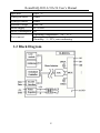
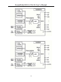
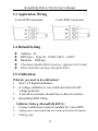
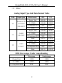
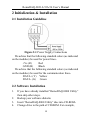
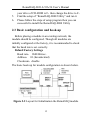
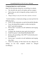
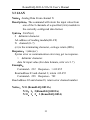
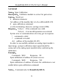
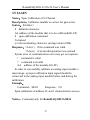
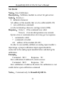
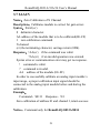
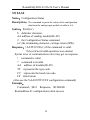
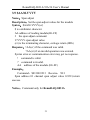
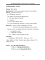
V1.1 2009.02.13
RemoDAQ-8031A
RemoDAQ-8033A
RemoDAQ-8034
User’s Manual
Beijing Gemotech Intelligent Technology Co.,Ltd
RemoDAQ-8031A/33A/34 User’s Manual
Copyright Notice
This document is copyrighted, 2005, by Beijing Gemotech
Intelligent Technology Co.,Ltd.
All rights are reserved. Beijing Gemotech Intelligent
Technology Co.,Ltd reserves the right to make
improvements to the products described in this manual at any
time without notice.
No part of this manual may be reproduced, copied,
translated or transmitted in any form or by any means without
the prior written permission of Beijing Gemotech Intelligent
Technology Co.,Ltd. Information provided in this manual is
intended to be accurate and reliable. However, Beijing
Gemotech Intelligent Technology Co.,Ltd assumes no
responsibility for its use, or for any infringements upon the
rights of third parties, which may result from its use.
Acknowledgments
RemoDAQ is a trademark of Beijing Gemotech Intelligent
Technology Co.,Ltd.
Edition 1.1
Feb. 2009
1
RemoDAQ-8031A/33A/34 User’s Manual
Additional Information and Assistance
1.
Visit the Gemotech websites at www. gemotech.cn in
which you can find the latest information about the product.
2.
Contact your distributor, sales representative, or
Gemotech 's customer service center for technical support if
you need additional assistance. Please have the following
information ready before you call:
z
Product name and serial number
z
Description of your peripheral attachments
z
Description of your software (operating system,
version,application software, etc.)
z
A complete description of the problem
z
The exact wording of any error messages
2
RemoDAQ-8031A/33A/34 User’s Manual
Table of Contents
1 Introduction .............................................................................................. 4
1.1 Pin Assignment & Specifications .............................................. 5
1.2 Block Diagram ........................................................................... 8
1.3 Application Wiring .................................................................. 10
1.4 Default Setting ......................................................................... 10
1.5 Calibration................................................................................ 10
1.6 Install List ................................................................................ 12
2 Initialization & Installation .................................................................... 14
2.1 Installation Guideline............................................................... 14
2.2 Software Installation ................................................................ 14
2.3 Basic configuration and hook-up............................................. 15
2.4 Baudrate and Checksum .......................................................... 17
3 Command Set ......................................................................................... 19
3.1 %AANNTTCCFF .................................................................... 22
3.2 #AA .......................................................................................... 24
3.3 #AAN ....................................................................................... 25
3.4 $AA0 ........................................................................................ 26
3.5 $AA0N ..................................................................................... 27
3.6 $AA1 ........................................................................................ 28
3.7 $AA1N ..................................................................................... 29
3.8 $AA2 ........................................................................................ 30
3.9 $AA30.VVVV ......................................................................... 31
3.10 $AA3NV.VVVV ................................................................... 32
3.11 $AA40±VVV.VV .................................................................. 33
3.12 $AA4N±VVV.VV ................................................................. 34
3.13 $AAF...................................................................................... 35
3.14 $AAM .................................................................................... 36
3.15 ~AAO(Data)........................................................................... 37
3.16 ~AAEV .................................................................................. 38
3
RemoDAQ-8031A/33A/34 User’s Manual
1 Introduction
The RemoDAQ-8000 Series is a set of intelligent sensor to
computer interface modules containing built in microprocessor. They are remotely controlled through a simple set of
commands issued in ASCII format and transmitted in RS-485
protocol. They provide signal conditioning, isolation, ranging,
A/D and D/A conversion, data comparison, digital communication, timer/counter, wireless communication, collection
AC and other functions.
RemoDAQ-8031A RTD Module
RemoDAQ-8031A RTD input module supports one RTD
input channel for temperature measurement. This module can
accept 2 wire, 3 wire RTD sensor. The module offers signal
conditioning, A/D conversion, ranging, and RS-485 digital
communication functions.
RemoDAQ-8033A is a three channel RTD input module.
RemoDAQ-8034 is a four channel RTD input module
The common features of analog input modules are given as
following :
z 16-bits sigma-delta ADC to provide excellent accuracy.
z 4-channels RTD direct connect
z Software calibration
4
RemoDAQ-8031A/33A/34 User’s Manual
1.1 Pin Assignment & Specifications
RemoDAQ-8031A Specifications:
Input channel
Input type
RTD type
Output
Speed (in bps)
Maximum distance
Conversion rate
Bandwidth
Accuracy
Zero drift
Span drift
CMR@50/60Hz
NMR@50/60Hz
Isolation voltage
Power supply
1
2,3 wire
Pt100;Cu100;Cu50
RS-485 (2-wire)
1200,2400,4800,9600,19.2K,38.4K,57.6K,115.2K
4000ft. (1200m.)
10samples/sec (60/50Hz)
5.24Hz
±0.1% or better
0.5µV/°C
1.0µV /°C
150dB
100dB
3000VDC
10~30VDC
5
RemoDAQ-8031A/33A/34 User’s Manual
Power consumption 1.0W
Operating Temperature:-20 ~ 70° C
Environment
Humidity:5 ~ 95%, non-condensing
RemoDAQ-8033A Specifications:
Input channel
Input type
RTD type
Output
Speed (in bps)
Maximum distance
Conversion rate
Bandwidth
Accuracy
Zero drift
Span drift
CMR@50/60Hz
3
2,3 wire
Pt100;Cu100;Cu50
RS-485 (2-wire)
1200,2400,4800,9600,19.2K,38.4K,57.6K,115.2K
4000ft. (1200m.)
10 samples/sec (60/50Hz)
5.24Hz
±0.1% or better
0.5µV/°C
1.0µV /°C
150dB
6
RemoDAQ-8031A/33A/34 User’s Manual
NMR@50/60Hz
Isolation voltage
Power supply
Power consumption
Environment
100dB
3000VDC
10~30VDC
1.0W
Operating Temperature:-20 ~ 70° C
Humidity:5 ~ 95%, non-condensing
RemoDAQ-8034 Specifications:
Input channel
Input type
RTD type
Output
Speed (in bps)
Maximum distance
Conversion rate
Bandwidth
Accuracy
Zero drift
4
4 wire
Pt100;Cu100;Cu50
RS-485 (2-wire)
1200,2400,4800,9600,19.2K,38.4K,57.6K,115.2K
4000ft. (1200m.)
10 samples/sec (60/50Hz)
5.24Hz
±0.1% or better
0.5µV/°C
7
RemoDAQ-8031A/33A/34 User’s Manual
Span drift
CMR@50/60Hz
NMR@50/60Hz
Isolation voltage
Power supply
Power consumption
Environment
1.0µV /°C
150dB
100dB
3000VDC
10~30VDC
1W
Operating Temperature:-20 ~ 70° C
Humidity:5 ~ 95%, non-condensing
1.2 Block Diagram
8
RemoDAQ-8031A/33A/34 User’s Manual
9
RemoDAQ-8031A/33A/34 User’s Manual
1.3 Application Wiring
2-wire RTD connection
3-wire RTD connection
1.4 Default Setting
z
z
z
z
z
Address:01
RTD type:Type 20,Pt100,-100℃~+100℃
Baudrate:9600 bps
Checksum disable,60Hz rejection,engineer unit format
Filter at 60 Hz rejection (except R-8036)
1.5 Calibration
What do you need to do calibration?
1. One 5 1/2 digital multimeter.
2. A voltage calibrator or very stable and noise free DC
voltage generator.
3. A precision resistance decade box or discrete resistors.
4. RemoDAQ-8000 Utility.
1.
2.
3.
Calibrate Order:(RemoDAQ-8031A)
Connect calibration resistor to module by 3-wire RTD
Apply power to the module and let it warm up for about 30 minutes
Setting type
10
RemoDAQ-8031A/33A/34 User’s Manual
4.
5.
6.
Enable calibration
Apply zero calibration resistance 001.00 Ohms
Perform $AA40±VVV.VV Command,output resistor
value 001.00
7. Perform Zero Calibration Command$AA1
8. Apply span calibration resistance 200.00Ohm
9. Perform $AA30V.VVVV Command,output resistor
value 200.00
10. Perform span calibration command $AA0
1.
2.
3.
4.
5.
6.
Calibrate Order:(RemoDAQ-8033A)
Connect calibration resistor to module by 3-wire RTD
Apply power to the module and let it warm up for about 30 minutes
Setting type
Enable calibration
Apply zero calibration resistance 001.00 Ohms
Perform $AA4N±VVV.VV Command,output resistor
value 001.00
7. Perform Zero Calibration Command$AA1N
8. Apply span calibration resistance 200.00Ohm
9. Perform $AA3NV.VVVV Command,output resistor
value 200.00
10. Perform span calibration command $AA0N
11. 0~2 channel is calibrated according to 5~10 step
1.
2.
3.
4.
Calibrate Order:(RemoDAQ-8034)
Connect calibration resistor to module by 3-wire RTD
Apply power to the module and let it warm up for about 30 minutes
Setting type
Enable calibration
11
RemoDAQ-8031A/33A/34 User’s Manual
5.
6.
Apply zero calibration resistance 001.00 Ohms
Perform $AA4N±VVV.VV Command,output resistor
value 001.00
7. Perform Zero Calibration Command$AA1N
8. Apply span calibration resistance 200.00Ohm
9. Perform $AA3NV.VVVV Command,output resistor
value 200.00
10. Perform span calibration command $AA0N
11. 0~3 channel is calibrated according to 5~10 step
1.6 Install List
Baudrate Setting (CC)
Code
03
04
05
06
07
08
09
0A
Baudrate 1200 2400 4800 9600 19200 38400 57600 115200
RTD type setting (TT)
Code
RTD type
20
Pt100
21
Cu100
22
Cu50
Temperature Range
-200 ~ 400
-50 ~ 150
-50 ~ 150
Data format setting(FF)
7
6
5
4
3
2
*1
*2
0
*1:0=60Hz Restrain
1=50Hz Restrain
*2:Checksum:0=Disabled 1=Enable
*3:00 = Engineering Unit Format
01 = Percentage Format
10 = 2’s Complement HEX Format
12
1
0
*3
RemoDAQ-8031A/33A/34 User’s Manual
11 = Ohms
Analog Input Type And Data Format Table
Code
Input span
Platinum 100
20
a=0.00385
-200~400℃
21
Cu100
Data format
-F.S
Project Unit
+400.00
-200.00
%(FSR)
+100.00
-050.00
2’s Complement HEX
7FFF
BFFF
Ohm
+247.09
+018.52
Project Unit
+150.00
-50.00
%(FSR)
+100.00
-033.33
-50~150℃ 2’s Complement HEX
Ohm
22
+F.S.
7FFF
D554
+164.27
+078.49
Project Unit
+100.00
+000.00
Cu50
%(FSR)
+100.00
-033.33
0~100℃
2’s Complement HEX
7FFF
D554
Ohm
+082.13
+039.24
RTD Over range / Under range Reading
Over rang
Under range
Project Unit
+9999
-0000
%(FSR)
+9999
-0000
2’s Complement HEX
7FFF
8000
13
RemoDAQ-8031A/33A/34 User’s Manual
2 Initialization & Installation
2.1 Installation Guideline
Figure 2-1 Power Supply Connections
We advise that the following standard colors (as indicated
on the modules) be used for power lines:
+Vs (R)
Red
GND (B)
Black
We advice that the following standard colors (as indicated
on the modules) be used for the communication lines:
DATA+ (Y) Yellow
DATA- (G) Green
2.2 Software Installation
1.
2.
3.
4.
If you have already installed “RemoDAQ-8000 Utility”
then skip other steps.
Backup your software diskette.
Insert “RemoDAQ-8000 Utility” disc into CD-ROM:
Change drive to the path of CD-ROM. For example,
14
RemoDAQ-8031A/33A/34 User’s Manual
5.
6.
your drive of CD-ROM is F:then change the drive to F:
Find the setup of “RemoDAQ-8000 Utility” and run it.
Please follow the steps of setup program then you can
successful to install the RemoDAQ-8000 Utility
2.3 Basic configuration and hook-up
Before placing a module in an existing network, the
module should be configured. Though all modules are
initially configured at the factory, it is recommended to check
that the baud rate is set correctly.
Default Factory Settings
Baud rate: 9600 Bit/sec.
Address: 01 (hexadecimal)
Checksum:disable
The basic hook-up for module configuration is shown below.
Figure 2-2 Layout for Initialization the RemoDAQ module
15
RemoDAQ-8031A/33A/34 User’s Manual
The following items are required to configure a module:a
RemoDAQ converter module, a personal computer with RS232 port (baudrate set to 9600) and theRemoDAQ utility software.
Configuration with the RemoDAQ Utility Software
The easiest way to configure the RemoDAQ module is by
using the RemoDAQ utility software:an easy-to-use menustructured program will guide you through every step of the
configuration.
Configuration with the RemoDAQ command set
RemoDAQ modules can also be configured by issuing
direct commands from within a terminal emulation program
that is part of the RemoDAQ utility software.
The following example guides you through the setup of an
analog input module. Assume that RemoDAQ-8031A still has
its default settings (baud rate 9600 and address 01h). Before
the module is reconfigured, it is first requested to send its
default settings.
To change the configuration setting of the analog input
module, the following command is issued:
%0107200600(cr)
% = change configuration
01 = target module at address 00 to:
07 = change address to 07 hexadecimal
20 = set input range to Type 20
06 = set baud rate to 9600
00 = set integration time to 50 ms (60 Hz)
disable checksum
16
RemoDAQ-8031A/33A/34 User’s Manual
set data format to engineering units
(See Chapter 3, Command Set for a full description of the
syntax of the configuration command for module)
When the module received the configuration command it will
respond with its new address:!07 (cr).
NOTICE: All reconfiguration except changing of baud rate
and checksum values can be done dynamically, i.e. the
modules need not to be reset. When changing the baud rate or
checksum, these changes should be made for all connected
devices. After reconfiguration, all modules should be
powered down and powered up to force a reboot and let the
changes take effect.
2.4 Baudrate and Checksum
RemoDAQ modules contain EEPROMs to store
configuration information and calibration constants. The
EEPROM replaces the usual array of switches and ports
required to specify baudrate, input/output range etc.
All of the RemoDAQ modules can be configured remotely
through their communication ports, without having to
physically alter port or switch settings.
Forcing the module in the INIT* state does not change any
parameters in the module’s EEPROM. When the module is in
the INIT* state with its INIT* and GND terminals shorted, all
configuration settings can be changed and the module will
respond to all other commands normally.
17
RemoDAQ-8031A/33A/34 User’s Manual
Changing Baud rate and Checksum
Baud rate and checksum settings have several things in common:
¾
¾
They should be the same for all modules and host computer.
Their setting can only be changed by putting a module in the
INIT* state.
¾
Changed settings can only take effect after a module is rebooted.
To alter baudrate or checksum settings you must perform the
following steps:
¾ Power on all components except the RemoDAQ Module.
¾ Power the RemoDAQ module on while shorting the
INIT* and GND terminals.
¾ Wait at least 7 seconds to let self calibration and ranging
take effect.
¾ Configure the checksum status and/or the baud rate.
¾ Switch the power to the RemoDAQ Module OFF.
¾ Remove the grounding of the INIT* terminal and power
the module on.
¾ Wait at least 7 seconds to let self calibration and ranging
take effect.
¾ Check the settings (If the baud rate has changed, the
settings on the host computer should be changed
accordingly.)
18
RemoDAQ-8031A/33A/34 User’s Manual
3 Command Set
Introduction
To avoid communication conflicts when several devices try
to send data at the same time, all actions are instigated by the
host computer. The basic form is a command/response
protocol with the host initiating the sequence.
When modules are not transmitting they are in listen mode.
The host issues a command to a module with a specified
address and waits a certain amount of time for the module to
respond. If no response arrives, a timeout aborts the sequence
and returns control to the host.
Changing RemoDAQ’s configuration might require the
module to perform auto calibration before changes can take
effect. Especially when changing the range, the module has to
perform all stages of auto calibration that it also performs
when booted. When this process is under way, the module
does not respond to any other commands.
The command set includes the exact delays that might
occur when modules are reconfigured.
Syntax
[delimiter character][address][command][data][checksum]
[carriage return]
Every command begins with a delimiter character. There
are four valid characters:a dollar sign $, a pound sign #, a
percentage sign % and an at sign @.
19
RemoDAQ-8031A/33A/34 User’s Manual
The delimiter character is followed by a two-character
address (hexadecimal) that specifies the target module. The
actual two-character command follows the address.
Depending on the command, an optional data segment
follows the command string. An optional two character
checksum may be appended to the total string. Every
command is terminated by a carriage return (cr).
Calculate Checksum:
1. Calculate ASCII sum of all characters of command(or
response) string except the character return(cr).
2. Mask the sum of string with 0ffh.
Example:
Command string:$012(cr)
Sum of string=‘$’+‘0’+‘1’+‘2’=24h+30h+31h+32h=B7h
The checksum is B7h,and [CHK] = “B7”
Command string with checksum:$012B7(cr)
Response string:!01200600(cr)
Sum of string:‘!’+‘0’+‘1’+‘2’+‘0’+‘0’+‘6’+‘0’+‘0’
=1h+30h+31h+32h+30h+30h+36h+30h+30h=1AAh
The checksum is AAh,and [CHK] = “AA”
Response string with checksum:!01200600AA(cr)
20
RemoDAQ-8031A/33A/34 User’s Manual
General Command Sets
Command Syntax Command Name
%AANNTTCCFF
#AA
#AAN
$AA0
$AA0N
$AA1
$AA1N
$AA2
$AA30V.VVVV
$AA3NV.VVVV
$AA40V.VVVV
$AA4NV.VVVV
$AAF
$AAM
~AAO(data)
~AAEV
Configuration
Command Description
Sets the address,input range,
baudrate,dataformat,checksum status
Return the input value from the
module in the currently configured
data format
Return the input value from the
Analog data in module channels N in the currently
configured data format
Calibrates an AI module to correct
Span calibration
for gain errors
Channel N span Calibrates channel N of the module
Calibration
to correct for gain errors
Calibrates an AI module to correct
Zero Calibration
for gain errors
Channel N Zero Calibrates channel N of the module
Calibration
to correct for gain errors
Return the configuration
Configuration status
parameters for the module
Set the span adjust values for the
Span adjust
module (RemoDAQ-8031A)
Set the span adjust values for the
Span adjust
module (RemoDAQ-8033A/34)
Set the zero adjust values for the
Zero adjust
module (RemoDAQ-8031A)
Set the zero adjust values for the
Zero adjust
module (RemoDAQ-8033A/34)
Read firmware version Return the firmware version code
Read module name Return the module name
Set module name Return correct or error
Enable/Disable
Return correct or error
calibration
Analog data in
21
Notes
3.1
3.2
3.3
3.4
3.5
3.6
3.7
3.8
3.9
3.10
3.11
3.12
3.13
3.14
3.15
3.16
RemoDAQ-8031A/33A/34 User’s Manual
3.1 %AANNTTCCFF
Name:Configuration
Description:Sets address, type code, baudrate, data format
Syntax:%AANNTTCCFF(cr)
%
delimiter character.
AA address of setting module (00-FF)
NN New address (00-FF)
TT New type
CC New baudrate
FF New data format
When changing baudrate or checksum, we should INIT* termination land.
7
6
5
4
3
2
1
0
Not used
Checksum status
0: Disable
1: Enable
0=60Hz Restrain 1=50Hz Restrain
00=Engineering Unit Format
01= Percentage Format
10= 2’s Complement HEX
11= Ohms
Figure 3-1 Data format setting of AI modules
Response:!AA(cr) if the command was valid.
?AA(cr) if an invalid operation was entered. if
the INIT* terminal was not grounded when attempting
to change baud rate or checksum settings.
Syntax error or communication error may get no response.
! command is valid.
22
RemoDAQ-8031A/33A/34 User’s Manual
? command is invalid.
AA address of setting module (00-FF)
(cr) is the terminating character, carriage return (0Dh)
Example:
Command:%0102200600(cr) Response:!02(cr)
Change address from 01 to 02,an input type 20, baud rate
9600, integration time 50 ms (60 Hz), engineering units data
format and no checksum checking or generation.
The response indicates that the command was received.
Table 3-1 Input Rang Codes (Type Code)
Code
20
21
22
RTD type
Pt100
Cu100
Cu50
Temperature Range
-200 ~ 400
-50 ~ 150
-50 ~ 150
Table 3-2 Baudrate Code
Code
03
04
05
06
07
Baudrate 1200 2400 4800 9600 19200
23
08
09
0A
38400 57600 115200
RemoDAQ-8031A/33A/34 User’s Manual
3.2 #AA
Name:Analog Data In
Description:Command will return the input value from
module in the currently configured data format.
Syntax #AA(cr)
# delimiter character.
AA address of reading module(00~FF)
(cr) is the terminating character, carriage return (0Dh).
Response:>(data)(cr)
Syntax error or communication error may get no response.
> delimiter character.
data AI input value,the data is the combination for each
channel respectively
Example:
Command:#01 Response:>+02.555
Read analog input value at address 01, return with +02.555
Command:#04 Response:>+02.422+05.457+04.654
Read analog input value at address 04(R-8033A), return
values of 3 channels.
24
RemoDAQ-8031A/33A/34 User’s Manual
3.3 #AAN
Name:Analog Data From channel N
Description:The command will return the input value from
one of the 8 channels of a specified (AA) module in
the currently configured data format.
Syntax:#AAN(cr)
# delimiter character.
AA address of reading module(00~FF)
N channel (0~7)
(cr) is the terminating character, carriage return (0Dh).
Response:>(data)(cr)
Syntax error or communication error may get no response.
> delimiter character.
data AI input value.(For data formats, refer sec.1.7).
Example:
Command:#32 Response:>+02.455
Read address 03 and channel 2, return +02.455
Command:#28 Response:?02
Read address 02 and channel 8, return error channel number
Notice:N=0 (RemoDAQ-8031A)
N=0,1,2(RemoDAQ-8033A)
N=0,1,2,3 (RemoDAQ-8034)
25
RemoDAQ-8031A/33A/34 User’s Manual
3.4 $AA0
Name:Span Calibration
Description:Calibrates module to correct for gain errors.
Syntax:$AA0 (cr)
$ delimiter character.
AA address of the module that is to be calibrated(00~FF)
0 span calibration command.
(cr) the terminating character, carriage return (0Dh).
Response:!AA(cr) if the command was valid.
?AA(cr) if an invalid operation was entered.
Syntax error or communication error may get no response.
! command is valid.
? command is invalid.
AA address of the module (00~FF)
In order to successfully calibrate an analog input module’s
input range, a proper calibration input signal should be
connected to the analog input module before and during the
calibration.
Example:
Command:$010
Response:!01
Span calibration of address 01,return success
Command:$020
Response:?02
Span calibration of address 02,return the calibration is not
enable before span calibration command
Notice:Command only for RemoDAQ-8031A
26
RemoDAQ-8031A/33A/34 User’s Manual
3.5 $AA0N
Name:Span Calibration of N Channel
Description:Calibrates module to correct for gain errors
Syntax:$AA0(cr)
$ delimiter character.
AA address of the module that is to be calibrated(00~FF)
0 span calibration command.
N channel
(cr) the terminating character, carriage return (0Dh).
Response:!AA(cr) if the command was valid.
?AA(cr) if an invalid operation was entered.
Syntax error or communication error may get no response.
! command is valid.
? command is invalid.
AA address of the module (00~FF)
In order to successfully calibrate an analog input module’s
input range, a proper calibration input signal should be
connected to the analog input module before and during the
calibration.
Example:
Command:$0101
Response:!01
Span calibration of address 01 and 1 channel,return success
Notice:Command only for RemoDAQ-8033A/8034
27
RemoDAQ-8031A/33A/34 User’s Manual
3.6 $AA1
Name:Zero Calibration
Description:Calibrates module to correct for gain errors
Syntax:$AA1(cr)
$ delimiter character.
AA address of the module that is to be calibrated(00~FF)
1 zero calibration command.
(cr) the terminating character, carriage return (0Dh).
Response:!AA(cr) if the command was valid.
?AA(cr) if an invalid operation was entered.
Syntax error or communication error may get no response.
! command is valid.
? command is invalid.
AA address of the module (00~FF)
In order to successfully calibrate an analog input module’s
input range, a proper calibration input signal should be
connected to the analog input module before and during the
calibration.
Example:
Command:$011
Response:!01
Zero calibration of address 01,return success
Command:$021
Response:?02
Zero calibration of address 02,return the calibration is not
enable before span calibration command
Notice:Command only for RemoDAQ-8031A
28
RemoDAQ-8031A/33A/34 User’s Manual
3.7 $AA1N
Name:Zero Calibration of N Channel
Description:Calibrates module to correct for gain errors
Syntax:$AA1(cr)
$ delimiter character.
AA address of the module that is to be calibrated(00~FF)
1 zero calibration command.
N channel
(cr) the terminating character, carriage return (0Dh).
Response:!AA(cr) if the command was valid.
?AA(cr) if an invalid operation was entered.
Syntax error or communication error may get no response.
! command is valid.
? command is invalid.
AA address of the module (00~FF)
In order to successfully calibrate an analog input module’s
input range, a proper calibration input signal should be
connected to the analog input module before and during the
calibration.
Example:
Command:$0111 Response:!01
Zero calibration of address 01 and channel 1,return success
Notice:Command only for RemoDAQ-8033A/8034
29
RemoDAQ-8031A/33A/34 User’s Manual
3.8 $AA2
Name:Configuration Status
Description:The command requests the return of the configuration
data from the analog input module at address AA.
Syntax:$AA2(cr)
$ delimiter character.
AA address of reading module(00~FF)
2 the Configuration Status command.
(cr) the terminating character, carriage return (0Dh).
Response:!AATTCCFF(cr) if the command is valid.
?AA(cr)if an invalid operation was entered.
Syntax error or communication error may get no response.
! command is valid.
? command is invalid.
AA address of module(00~FF)
TT represents the type code.
CC represents the baud rate code.
FF data format
(Also see the %AANNTTCCFF configuration command)
Example:
Command:$012 Response:!01200600
Read address 01 configuration,return success
30
RemoDAQ-8031A/33A/34 User’s Manual
3.9 $AA30.VVVV
Name:Span adjust
Description:Set the span adjust values for the module
Syntax:$AA30.VVVV(cr)
$ is a delimiter character.
AA address of reading module(00~FF)
3 the span adjust command.
V.VVVV span adjust value
(cr) is the terminating character, carriage return (0Dh)
Response:!AA(cr) if the command was valid.
?AA(cr) if an invalid operation was entered.
Syntax error or communication error may get no response.
! command is valid.
? command is invalid.
AA address of the module (00~FF)
Example:
Command:$01300.9213 Receive:!011
Span address 01 channel span adjust value 0.9213,return
success.
Notice:Command only for RemoDAQ-8031A
31
RemoDAQ-8031A/33A/34 User’s Manual
3.10 $AA3NV.VVVV
Name:Span adjust
Description:Set the span adjust values for the module
Syntax:$AA3N.VVVV(cr)
$ is a delimiter character.
AA address of reading module(00~FF)
3 the span adjust command.
N channel
V.VVVV span adjust value
(cr) is the terminating character, carriage return (0Dh)
Response:!AA(cr) if the command was valid.
?AA(cr) if an invalid operation was entered.
Syntax error or communication error may get no response.
! command is valid.
? command is invalid.
AA address of the module (00~FF)
Example:
Command:$02310.9213 Receive:!011
Span address 02 and 1 channel span adjust value 0.9213,
return success.
Notice:N=0 (RemoDAQ-8031A)
N=0,1,2(RemoDAQ-8033A)
N=0,1,2,3 (RemoDAQ-8034)
32
RemoDAQ-8031A/33A/34 User’s Manual
3.11 $AA40±VVV.VV
Name:Zero adjust
Description:Set the zero adjust values for the module
Syntax:$AA40±VVV.VV(cr)
$ is a delimiter character.
AA address of reading module(00~FF)
4 the zero adjust command.
±VVV.VV zero adjust value
(cr) is the terminating character, carriage return (0Dh)
Response:!AA(cr) if the command was valid.
?AA(cr) if an invalid operation was entered.
Syntax error or communication error may get no response.
! command is valid.
? command is invalid.
AA address of the module (00~FF)
Example:
Command:$0140-000.18 Receive:!011
Span address 01 channel zero adjust value –000.18, return
success.
Notice:Command only for RemoDAQ-8031A
33
RemoDAQ-8031A/33A/34 User’s Manual
3.12 $AA4N±VVV.VV
Name:Zero adjust
Description:Set the zero adjust values for the module
Syntax:$AA4N±VVV.VV(cr)
$ is a delimiter character.
AA address of reading module(00~FF)
4 the zero adjust command.
N channel
±VVV.VV zero adjust value
(cr) is the terminating character, carriage return (0Dh)
Response:!AA(cr) if the command was valid.
?AA(cr) if an invalid operation was entered.
Syntax error or communication error may get no response.
! command is valid.
? command is invalid.
AA address of the module (00~FF)
Example:
Command:$0242+000.16 Receive:!011
Span address 02 and 2 channel zero adjust value 000.16,
return success.
Notice:N=0 (RemoDAQ-8031A)
N=0,1,2(RemoDAQ-8033A)
N=0,1,2,3 (RemoDAQ-8034)
34
RemoDAQ-8031A/33A/34 User’s Manual
3.13 $AAF
Name:Read Firmware Version
Description:The command requests the module at address
AA to return the version code of its firmware.
Syntax:$AAF (cr)
$ delimiter character.
AA address of reading module(00~FF)
F identifies the version command.
(cr) is the terminating character, carriage return (ODh)
Response: !AA(data)(cr) if the command is valid.
?AA (cr) if an invalid command was issued.
Syntax error or communication error may get no response.
! command is valid.
? command is invalid.
AA address of response module(00~FF)
Data is the version code of the module’s firmware.
Example:
Command:$01F Receive:!01041201
Read address 01 firmware version,return version 041201
Command:$02F Receive:!01050101
Read address 02 firmware version,return version 050101
35
RemoDAQ-8031A/33A/34 User’s Manual
3.14 $AAM
Name:Read Module Name
Description:The command requests the module at address
AA to return its name
Syntax:$AAM (cr)
$ delimiter character.
AA address of reading module(00~FF)
M the Read Module Name command.
(cr) is the terminating character, carriage return (ODh)
Response:!AA(data)(cr) if the command is valid.
?AA(cr) if an invalid command was issued.
Syntax error or communication error may get no response.
! command is valid.
? command is invalid.
AA address of response module(00~FF)
data the name of the module
Example:
Command:$01M Receive:!018034
Read address 01 module name,return name 8034.
Command:$03M Receive:!038034
Read address 03 module name,return name 8034.
36
RemoDAQ-8031A/33A/34 User’s Manual
3.15 ~AAO(Data)
Name:Set Module Name
Description:Set the module name and return success or error.
Syntax:~AAO(Data) (cr)
$ delimiter character.
AA address ofsetting module(00~FF)
O Set Module Name command.
Data new name for module,max 6 characters
(cr) is the terminating character, carriage return (ODh)
Response:!AA(cr) if the command is valid.
?AA(cr) if an invalid command was issued.
Syntax error or communication error may get no response.
! command is valid.
? command is invalid.
AA address of response module(00~FF)
Example:
Command:~01O8034 Receive:!01
Set address 01 module name to 8034,return success.
Command:$01M
Receive:!018034
Read address 01 module name,return 8034.
37
RemoDAQ-8031A/33A/34 User’s Manual
3.16 ~AAEV
Name:Enable/Disable Calibration
Syntax:~AAEV (cr)
$ delimiter character.
AA address of reading module(00~FF)
E Enable/Disable calibration command.
V 1=Enable 0=Disable
(cr) is the terminating character, carriage return (ODh)
Response:!AA(cr) if the command is valid.
?AA(cr) if an invalid command was issued.
Syntax error or communication error may get no response.
! command is valid.
? command is invalid.
AA address of response module(00~FF)
Example:
Command:$010
Receive:?01
Perform address 01 span calibration,return the command is
invalid before enable calibration.
Command:~01E1 Receive:!01
Set address 01 to enable calibration,return success.
Command:$010
Receive:!01
Perform address 01 span calibration,return success.
38