1
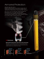
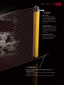
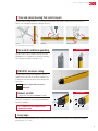
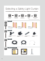
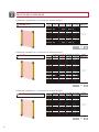
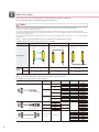
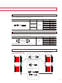
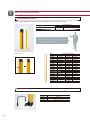
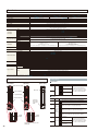
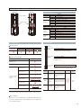
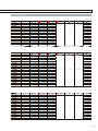
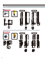
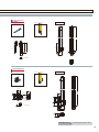
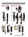
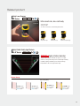
NEW
Safety Light Curtain
GL-R Series
Maximum safety standard
Type4
SIL3
PLe
Armored Protection!
Safety Light Curtain
Strong × Simple × Smart
GL-R Series
Armored Protection
What makes a light curtain "robust"?
KEYENCE conducted in-depth research to determine how light curtains are
damaged and learned that the most common cause is damage to the lens
surface when it is scratched, cracked, or otherwise broken due to impact from
parts or tools. In some cases, light curtains have been installed with userfabricated protective covers or housing to prevent this damage.
As a result of this research, KEYENCE has designed a light curtain with a
structure that prevents damage from parts or tools by narrowing the exposed
lens area and recessing it in an impact resistant housing.*
* the narrowest lens surface aperture in the industry, according to KEYENCE research as of March, 2012
Strong
Built-in guarding and the narrowest exposed lens surface in the industry.
With its narrow (0.35" 9mm wide) and recessed lens surface, the GL-R Series is protected
against impact and resultant damage from parts, tools or operators without the need for
any additional guards or covers. Additionally, the GL-R Series is protected from water and
washdown environments due to its IP65/67 enclosure ratings.
Operating distance
Operating distance
Operating distance
0.66' to 32.81'
0.2 to 10 m
0.66' to 49.21'
0.2 to 15 m
0.66' to 49.21'
0.2 to 15 m
Detection capability
Detection capability
Detection capability
ø0.55"
ø14 mm
ø0.98"
ø25 mm
ø1.77"
ø45 mm
GL-RF Series
2
GL-RH Series
GL-RL Series
Strong × Simple × Smart
Smart
No Dead Zone
Because the first beam is emitted
0.39" 10 mm* from each end, the light
curtain can be mounted flush inside
of equipment, eliminating the need for
additional guarding or outside mounting.
*Except GL-RL Series
7-segment display
If an error is ever detected by the light
curtain, the 7-segment display provides
a code that indicates the cause, which
greatly reduces the time required to take
corrective action.
One-line Wiring System
Reduce connections to as few as 5 wires
by using this system that eliminates
transmitter wiring completely.
Simple
Reduce installation time with simple wiring and easy-to-use
mounting brackets.
The introduction of the one-line wiring system and optical synchronization simplifies
connections to as few as 5 wires.
Mounting brackets come pre-assembled to provide simple, one-step installation.
3
Strong
Securely protects the detection area
Built-in guarding will completely prevent impact to the lens surface by parts or tools of ø0.67" ø17 mm or more.*
Conventional Light Curtain
GL-R Series
Narrow
Recessed
*See specifications for guaranteed values.
4
Lens surface
Lens surface
Strong × Simple × Smart
Thick and robust housing that resists impact
The GL-R Series is designed with a 0.12" 3 mm thick housing that protects the light curtain body from various forms of
impact, such as dropping equipment or hitting it with tools.*
Hitting
Dropping
Stepping, Kicking
*See specifications for guaranteed values.
No need for additional guarding
Conventional Light Curtain
GL-R Series
Conventional Light Curtain
GL-R Series
The GL-R Series can be installed and remain protected
WITHOUT the use of additional U-channel type guarding,
which simplifies installation and reduces cost.
IP65/IP67 enclosure rating
The GL-R Series housing meets IP65/IP67 enclosure
ratings based on IEC and JIS standards, enabling its use
in washdown environments without fear of damage to the
light curtain.
IP65
Water-jet (washdown) resistant
IP67
Watertight
Robust, yet slim
(compared to conventional KEYENCE models)
The overall size of the GL-R Series has been reduced to
save space on equipment while maintaining KEYENCE's
high level of durability.
33 % reduction in size compared to the
conventional model
1.50"
38 mm
1.83"
46.5 mm
1.57"
40 mm
1.26"
32 mm
Long range
The range of the GL-RH and GL-RL Series models have been increased over past models for use in applications requiring
protection up to 49.21' 15 m.
5
Simple
One-line system
[Recommended for smaller, single operation pieces of equipment]
•Reduce the number of wires from 18 to 5
•1/3 of the wiring installation time compared to
conventional light curtains
Simplified wiring
One-line system
Conventional Light Curtain
18
wires
6
5
wires
The transmitter and receiver had to be routed through the
The transmitter receives power from the receiver, meaning
machine and wired to the control panel.
that only the receiver has to be wired to the control panel.
Strong × Simple × Smart
Advantages of the one-line system
1 Wiring is simplified by connecting the transmitter directly to the receiver, requiring that only the receiver be wired.
2 Reduced risk of mis-wiring due to the reduction in required connections.
One-line system
Conventional Light Curtain
One-line
system
Wiring routed
through the
machine
Control panel
5
Receiver
wires
Example of
wiring
Transmitter
18
Receiver
Transmitter
Example of
wiring
Control panel
wires
Orange
(Communication cable 1)
K2
K1
R2
(0V) Blue
(FE) Gray
(OSSD2) White
72%
(+24 V) Brown
Reduction in
installation time up to
(OSSD1) Black
Shield
(0V) Blue
(EDM input) Red
(OSSD1) Black
(Reset input) Yellow
(+24 V) Brown
(OSSD2) White
(+24 V) Brown
(Wait input) Purple
(Interlock mode selection input) Pink
(AUX output) Red
(Interlock-reset-ready output) Green
Shield
(0V) Blue
Orange/black
(Communication cable 2)
R1
Optical synchronization [Recommended for larger pieces of equipment or work cells]
•Reduced wiring
Separate transmitter and receiver wiring simplifies installation
Conventional Light Curtain
Synchronization wiring is required.
Optical synchronization
The transmitter and receiver can be wired separately,
which greatly simplifies wiring and installation time. Long
lengths of cable are no longer required to be routed
through the machine.
7
Simple
Quick fit brackets
Adjustable angle mounting bracket
Vertical
Horizontal
Straight / L-shaped mounting bracket
No dead zone mounting bracket
[ Easy installation ]
1. No assembly required
Traditionally, mounting brackets have required assembly
Conventional brackets
before installation. However, the GL-R Series brackets
come pre-assembled, so installation is as simple as
sliding them into the mounting track and securing them
to the machine.
2. Insert the bracket into the mounting track
The GL-R Series is designed to simplify mounting by
inserting the brackets into the mounting track and
locking them in place.
3. Mount directly to standard extruded aluminum framework
The GL-R Series mounting brackets have been designed
to attach directly to standard extruded aluminum
framework without the need for any additional hardware.
8
GL-R Series
Strong × Simple × Smart
Smart
Conventional Light Curtain
No Dead Zone
Dead Zone
Because the first beam is emitted
0.39" 10 mm* from each end, the
light curtain can be mounted flush
inside of equipment, eliminating
the need for additional guarding or
outside mounting.
*Except GL-RL Series
GL-R
Dead
Zone
0.39"
10 mm*
Side-Exit Cable
No Dead Zone
7-segment & center indicators
7-segment display
Errors are displayed as numeric codes, which reduces the amount of
time spent identifying and correcting the problem that was detected by
the GL-R Series.
Center indicator
These indicators highlight the operational status of the GL-R Series to
the user. The indicators change color to identify if the light curtain is
clear, interrupted, or in a lockout condition.
9
Smart
Built-in functionality
1 Mutual interference prevention
Mutual interference between 2 units can be prevented.
2 Reduced resolution function*
This function expands the size of the detection capability.
Up to 2 axes can be disabled.
*When the single zone mode is used
3 Center indicator function control
The center indicators can be turned off to reduce current
consumption.
Built-in series connection ability
0.79"
20 mm*
The coverage of the GL-R Series can be easily expanded by
connecting additional units in series. All models include this
feature as standard.
*Ex
*Except
GL-RL Series.
QD connector
The GL-R Series can easily be connected to a general-purpose,
M12 quick disconnect port or cable.
Corner mirror
Corner mirrors are available to allow 1 set of curtains to cover up
to 4 sides of a machine and reduce the amount of wiring required.
10
Strong × Simple × Smart
Advanced Option
Download site www.keyence.com/glr_soft
PC configuration software
Safety device configurator (free download)
Monitoring function
The operation of the GL-R Series can be monitored
with a PC. The status of I/O signals including OSSD
outputs, override inputs, and error conditions can
be checked as well as light intensity. In addition,
monitoring the mute condition will help to easily
identify causes of abnormal operation during the
muting setup or operation.
OFF information,
Error information,
Error history
OSSD output OFF time, location, and duration can
be easily checked by accessing the OFF information.
The Error code, time of occurrence, and conditions
can be checked by accessing the Error Information.
All Error codes and order of occurrence are saved
as Error history records, allowing the past history to
OFF information
be checked. This allows for easier troubleshooting
and analysis.
Error information
11
Selecting a Safety Light Curtain
Use the following steps to select the optimum GL-R Series components for your application.
s tep
step
step
step
step
1
2
3
4
5
Select the light
curtain type
Select the light
curtain length
Select the
mounting bracket
Select the
cables
Select the optional
accessories*
*Optional accessories are not required for normal operation.
step
Curtains
1
step
2
GL-RF Series
Detection capability
ø0.55” ø14 mm
step
GL-RH Series
Detection capability
ø0.98” ø25 mm
GL-RL Series
Detection capability
ø1.77” ø45 mm
Brackets
3
step
Adjustable angle mounting bracket
No dead zone mounting bracket
Straight mounting bracket
L-shaped mounting bracket
GL-RB01
GL-RB21
GL-RB11
GL-RB12
Cables
4
step
Optional Accessories
5
Front protection cover
12
Interface unit
Corner mirror
step
1
Select the light curtain type
Select a model according to the distance to the equipment hazard.
Detection capability: ø0.55” ø14 mm
Beam axis pitch of 0.39” ø10 mm.
Entry detection
To step 2
GL-RF
P.14
Detection capability: ø0.98” ø25 mm
Beam axis pitch of 0.79” ø20 mm.
Entry detection
To step 2
GL-RH
P.14
Detection capability: ø1.77” ø45 mm
Beam axis pitch of 1.57” ø40 mm.
Entry/presence detection
To step 2
GL-RL
P.14
The required mounting distance from the hazard is determined
by the response time and detection capability for the light curtain
that has been selected. Though the ø0.98” ø25 mm model is used
most frequently, if the distance to the hazard is short, select the
ø0.55” ø14 mm model. If the distance to the hazard is long, you
can use the ø1.77” ø45 mm model.
13
step
2
Select the light curtain length
If [Detection capability: ø0.55” ø14 mm] was selected in Step 1
GL-RF Series
Model
GL-R23F
GL-R31F
GL-R39F
GL-R47F
GL-R55F
GL-R63F
GL-R71F
GL-R79F
GL-R87F
GL-R95F
GL-R103F
GL-R111F
GL-R119F
GL-R127F
No. of beam Total length Detection height Protection height
Operating
axes
(inch mm)
(inch mm)
(inch mm)
distance (ft. m)
23
31
39
47
55
63
71
79
87
95
103
111
119
127
9.45”
12.60”
15.75”
18.90”
22.05”
25.20”
28.35”
31.50”
34.65”
37.80”
40.94”
44.09”
47.24”
50.39”
240
320
400
480
560
640
720
800
880
960
1040
1120
1200
1280
8.66”
11.81”
14.96”
18.11”
21.26”
24.41”
27.56”
30.71”
33.86”
37.01”
40.16”
43.31”
46.46”
49.61”
220
300
380
460
540
620
700
780
860
940
1020
1100
1180
1260
9.61”
12.76”
15.91”
19.06”
22.20”
25.35”
28.50”
31.65”
34.80”
37.95”
41.10”
44.25”
47.40”
50.55”
244
324
404
484
564
644
724
804
884
964
1044
1124
1204
1284
To step 3
0.67’ to 32.81’
0.2 to 10
P.15
If [Detection capability: ø0.98” ø25 mm] was selected in Step 1
GL-RH Series
Model
GL-R08H
GL-R12H
GL-R16H
GL-R20H
GL-R24H
GL-R28H
GL-R32H
GL-R36H
GL-R40H
GL-R44H
GL-R48H
GL-R52H
GL-R56H
GL-R60H
GL-R64H
GL-R72H
GL-R80H
GL-R88H
GL-R96H
No. of beam Total length Detection height Protection height
Operating
axes
(inch mm)
(inch mm)
(inch mm)
distance (ft. m)
8
12
16
20
24
28
32
36
40
44
48
52
56
60
64
72
80
88
96
6.30”
9.45”
12.60”
15.75”
18.90”
22.05”
25.20”
28.35”
31.50”
34.65”
37.80”
40.94”
44.09”
47.24”
50.39”
56.69”
62.99”
69.29”
75.59”
160
240
320
400
480
560
640
720
800
880
960
1040
1120
1200
1280
1440
1600
1760
1920
5.51”
8.66”
11.81”
14.96”
18.11”
21.26”
24.41”
27.56”
30.71”
33.86”
37.01”
40.16”
43.31”
46.46”
49.61”
55.91”
62.20”
68.50”
74.80”
140
220
300
380
460
540
620
700
780
860
940
1020
1100
1180
1260
1420
1580
1740
1900
7.28”
10.43”
13.58”
16.73”
19.88”
23.03”
26.18”
29.33”
32.48”
35.63”
38.78”
41.93”
45.08”
48.23”
51.38”
57.68”
63.98”
70.28”
76.57”
185
265
345
425
505
585
665
745
825
905
985
1065
1145
1225
1305
1465
1625
1785
1945
To step 3
0.67’ to 49.21’
0.2 to 15
P.15
If [Detection capability: ø1.77” ø45 mm] was selected in Step 1
GL-RL Series
Model
GL-R04L
GL-R06L
GL-R08L
GL-R10L
GL-R12L
GL-R14L
GL-R16L
GL-R18L
GL-R20L
GL-R22L
GL-R24L
GL-R26L
GL-R28L
GL-R30L
GL-R32L
No. of beam Total length Detection height Protection height
Operating
axes
(inch mm)
(inch mm)
(inch mm)
distance (ft. m)
4
6
8
10
12
14
16
18
20
22
24
26
28
30
32
6.30”
9.45”
12.60”
15.75”
18.90”
22.05”
25.20”
28.35”
31.50”
34.65”
37.80”
40.94”
44.09”
47.24”
50.39”
160
240
320
400
480
560
640
720
800
880
960
1040
1120
1200
1280
4.72”
7.87”
11.02”
14.17”
17.32”
20.47”
23.62”
26.77”
29.92”
33.07”
36.22”
39.37”
42.52”
45.67”
48.82”
120
200
280
360
440
520
600
680
760
840
920
1000
1080
1160
1240
8.07”
11.22”
14.37”
17.52”
20.67”
23.82”
26.97”
30.12”
33.27”
36.42”
39.57”
42.72”
45.87”
49.02”
52.17”
205
285
365
445
525
605
685
765
845
925
1005
1085
1165
1245
1325
To step 3
14
0.67’ to 49.21’
0.2 to 15
P.15
step
3
Select the mounting bracket
Adjustable angle mounting bracket GL-RB01
Side
mounting
45°
mounting
Rear
mounting
45°
mounting
Side
mounting
(incl. 2 pieces)
• By changing the screw positions, it is possible to
adjust the angle of the light curtain by 180°.
If the total length of the GL-R main unit is 50.39” 1280 mm or
longer, and if mounting it using the Adjustable angle mounting
bracket, also use the antivibration bracket (GL-RB32) to
prevent vibration.
To step 4
No dead zone mounting bracket GL-RB21
P.16
(incl. 2 pieces)
Useful when mounting brackets cannot be used on the top or bottom of the light curtain
• Allows you to rotate the light curtain 90° by
changing the mounting hole. It is also possible to
perform fine-tuning of ±15° from this position.
90° rotation
If the total length of the GL-R main unit is 50.39” 1280 mm
or longer and if mounting it using the no dead zone mounting
bracket, also use the antivibration bracket (GL-RB32) to
prevent vibration.
Straight mounting bracket GL-RB11
To step 4
P.16
To step 4
P.16
To step 4
P.16
(incl. 2 pieces)
• Simple attachment to standard machine
framework.
If the total length of the GL-R main unit is 50.39” 1280 mm
or longer, and if mounting it using the straight mounting
bracket, also use the antivibration bracket (GL-RB31) to
prevent vibration.
L-shaped mounting bracket GL-RB12
(incl. 2 pieces)
• Simple attachment to standard machine
framework.
If the total length of the GL-R main unit is 50.39” 1280 mm
or longer, and if mounting it using the L-shaped mounting
bracket, also use the L-shaped mounting bracket (GL-RB12)
to prevent vibration.
15
step
4
Select the cables
It is possible to select from the following 3 types of wiring systems according to the application.
Select an applicable cable according to the wiring systems listed below.
Cables
• Each model is connected to one cable. Therefore, at least two cables are needed as a system, one for the transmitter and another for the receiver.
• All cables can be used for both the transmitter and receiver.
• The combination of the wiring system and cable determines the functions that can be used. Different types of cables can be used for the transmitter and receiver.
• Make sure that the length of the main unit connection cable and extension cable will be 98.43’ 30 m or less regarding the transmitter and receiver, respectively, when using
the optical/wire synchronization system.
• Make sure that the total length for all cables, which includes the unit connection cable, extension cable, and series connection cable, is 98.43’ 30 m or less when using the
one-line system.
Select 1 cable for each transmitter/receiver according to the optimal wiring system.
If multiple functions are necessary, select an 11-core cable.
Wiring system
Optical synchronization system
Transmitter
One-line system
Transmitter
Receiver
Wire synchronization system
Receiver
Transmitter
Receiver
Wiring diagram
TransmitApplicable ter
Cables
Receiver
5-core cable
Series connection cable
7-core cable
11-core cable
5-core cable
11-core cable
5-core cable
11-core cable
7-core cable
11-core cable
Select a unit connection cable or one-line system series connection cable.
If extending the cable, select a connector type.
Shape
No. of
conductors
PNP/NPN
PNP
5-core
NPN
PNP
Unit connection cable
7-core
NPN
PNP
11-core
NPN
5-core
7-core
Unit connection cable
(for extension use)
11-core
Series connection
cable
The connector shape for both sides is the same.
16
PNP
NPN
PNP
NPN
PNP
NPN
PNP/NPN shared
Connector
Length (ft. m)
Model
—
16.40’
5
GL-RP5P
—
32.81’
10
GL-RP10P
—
16.40’
5
GL-RP5N
—
32.81’
10
GL-RP10N
—
16.40’
5
GL-RP5PS
—
32.81’
10
GL-RP10PS
—
16.40’
5
GL-RP5NS
—
32.81’
10
GL-RP10NS
—
16.40’
5
GL-RP5PM
—
32.81’
10
GL-RP10PM
—
16.40’
5
GL-RP5NM
—
32.81’
10
GL-RP10NM
GL-RPC03P
M12 (5-pin male)
M12 (8-pin male)
GL-RPC03N
0.98’ 0.3
GL-RPC03PM
M14 (12-pin male)
—
GL-RPC03PS
GL-RPC03NS
GL-RPC03NM
0.26’ 0.08
GL-RS008
0.49’ 0.15
GL-RS015
1.64’ 0.5
GL-RS05
3.28’
1
GL-RS1
9.84’
3
GL-RS3
16.40’
5
GL-RS5
32.81’
10
GL-RS10
For extension
• If using a combination of the unit connection cable (for extension use) and the extension cable,
make sure that they share the same amount of conductors.
Shape
No. of conductors
Extension cable
PNP/NPN
Length (ft. m)
Model
5-core
M12 connector
(5-pin female)
16.40’
65.62’ 20
GL-RC20
7-core
M12 connector
(8-pin female)
16.40’
5
GL-RC5S
32.81’ 10
GL-RC10S
65.62’ 20
GL-RC20S
PNP/NPN
shared
5
GL-RC5
32.81’ 10
GL-RC10
16.40’
11-core
M14 connector
(12-pin female)
5
GL-RC5M
32.81’ 10
GL-RC10M
65.62’ 20
GL-RC20M
For series connection
By connecting up to 3 GL-R units in a series, they can function as a single set of light curtains.
• Use a series connection cable to perform series connection.
Shape
PNP/NPN
PNP/NPN
shared
*The connector shape for both sides is the same. There are no regulations for the direction in
which connection is performed.
Length (ft. m)
Model
0.26’ 0.08
GL-RS008
0.49’ 0.15
GL-RS015
1.64’
0.5
GL-RS05
3.28’
1
GL-RS1
9.84’
3
GL-RS3
16.40’
5
GL-RS5
32.81’
10
GL-RS10
Installation schematic
Optical synchronization/
Wire synchronization system
One-line system
• Series connection cable
• Unit connection cable
• Unit connection cable (for extension use)
+ extension cable
*The unit connection cable cannot be installed
on top of the GL-R.
17
step
5
Select the optional accessories
Front protection cover
Select a front protection cover to protect the detection surface as necessary.
Front protection cover
GL-RF
Operating distance
GL-RH
GL-RL
Single side (Transmitter or receiver only)
31.17’ 9.5 m
47.57’ 14.5 m
Both sides (Transmitter and receiver)
29.53’
45.93’
9m
14 m
Think of the front protection cover as a replaceable item.
When heavily soiled, melted due to spatter, or damaged due to
impact, replace the cover with a new one.
Two sets are required to install protection on
both the transmitter and receiver. Refer to the
detection distances in the chart when using the
front protection cover.
Model
Applicable GL-R model
GL-RA160
—
GL-R08H
GL-R04L
GL-RA240
GL-R23F
GL-R12H
GL-R06L
GL-RA320
GL-R31F
GL-R16H
GL-R08L
GL-RA400
GL-R39F
GL-R20H
GL-R10L
GL-RA480
GL-R47F
GL-R24H
GL-R12L
GL-RA560
GL-R55F
GL-R28H
GL-R14L
GL-RA640
GL-R63F
GL-R32H
GL-R16L
GL-RA720
GL-R71F
GL-R36H
GL-R18L
GL-RA800
GL-R79F
GL-R40H
GL-R20L
GL-RA880
GL-R87F
GL-R44H
GL-R22L
GL-RA960
GL-R95F
GL-R48H
GL-R24L
GL-RA1040
GL-R103F
GL-R52H
GL-R26L
GL-RA1120
GL-R111F
GL-R56H
GL-R28L
GL-RA1200
GL-R119F
GL-R60H
GL-R30L
GL-RA1280
GL-R127F
GL-R64H
GL-R32L
GL-RA1440
—
GL-R72H
—
GL-RA1600
—
GL-R80H
—
GL-RA1760
—
GL-R88H
—
GL-RA1920
—
GL-R96H
—
Interface unit
Optional accessory required to perform configuration and monitoring of the GL-R on a PC.
Model
18
Name
GL-R1UB
Interface unit
OP-51580
USB cable 6.56’ 2 m
OP-86941
USB cable 16.40’ 5 m
Corner mirror SL-M Series
By using a corner mirror, it is possible to reduce costs and save time on wiring.
• This is a mirror that reflects light from the transmitter within a range of 45° to 95°. Up to 4 mirrors can be used.
For details, see the “SL-M Series instruction manual”.
Model
For each single corner mirror,
the detection distance will decrease
by approximately 10%.
Applicable GL-R model
SL-M12H
GL-R23F
GL-R08H/GL-R12H
GL-R04L/GL-R06L
SL-M16H
GL-R31F
GL-R16H
GL-R08L
SL-M20H
GL-R39F
GL-R20H
GL-R10L
SL-M24H
GL-R47F
GL-R24H
GL-R12L
SL-M28H
GL-R55F
GL-R28H
GL-R14L
SL-M32H
GL-R63F
GL-R32H
GL-R16L
SL-M36H
GL-R71F
GL-R36H
GL-R18L
SL-M40H
GL-R79F
GL-R40H
GL-R20L
SL-M44H
GL-R87F
GL-R44H
GL-R22L
SL-M48H
GL-R95F
GL-R48H
GL-R24L
SL-M52H
GL-R103F
GL-R52H
GL-R26L
SL-M56H
GL-R111F
GL-R56H
GL-R28L
SL-M60H
GL-R119F
GL-R60H
GL-R30L
SL-M64H
GL-R127F
GL-R64H
GL-R32L
SL-M80H*
—
GL-R72H/GL-R80H
—
SL-M96H*
—
GL-R88H/GL-R96H
—
* Newly added to the lineup
19
Specifications
Model
Beam axis spacing/Lens diameter
Detection capability
Operating distance
Effective aperture angle
Light source
GL-RF
GL-RH
GL-RL
0.39” 10 mm / ø0.16” ø4
ø0.55" ø14 mm
0.66 to 32.81' 0.2 to 10 m*1
0.79” 20 mm / ø0.20” ø5
ø0.98" ø25 mm
1.57” 40 mm / ø0.20” ø5
ø1.77" ø45 mm
Response time
OSSD operation
Synchronization between the transmitter and receiver
Light interference prevention function
Control output
(OSSD output)
Supplemental output
(Non-safety-related output)
Output
Max. load current
Residual voltage (during ON)
OFF state voltage
Leakage current
Max. capacitive load
Load wiring resistance
AUX
Error output
External input
Power supply
2 transistor outputs. (PNP or NPN is determined by the cable type)
Load current: Max. 50 mA, Residual voltage: Max. 2.5 V (with a cable length of 16.40' 5 m )
Incandescent lamp (24 VDC, 1 to 5.5 W)
LED lamp (load current: 10 to 230 mA) can be connected
Muting lamp output
EDM input
Wait input
Reset input
Muting input 1, 2
Override input
Voltage
Current consumption
[When using a PNP output cable]
ON voltage: 10 to 30 V
OFF voltage: Open or 0 to 3 V
Short circuit current: Approx. 2.5 mA (Approx. 10 mA with EDM input only)
Material
Enclosure rating
Overvoltage category
Ambient temperature
Storage ambient temperature
Relative humidity
Storage relative humidity
Ambient light
Vibration
Shock
Main unit case
Upper case/lower case
Front cover
Weight
EMS
EMI
EMC
[When using an NPN output cable]
ON voltage: 0 to 3 V
OFF voltage: Open or 10 V or more
Up to the power voltage
Short circuit current: Approx. 2.5 mA (Approx. 10 mA with EDM input only)
24 VDC ±20%, ripple (P-P) 10% or less, Class 2
Transmitter : 37 to 81mA, Receiver : 66 to 91 mA
Reverse current protection, short-circuit protection for each output, surge protection for each output
IP65/IP67 (IEC60529)
II
14 to +131°F -10 to +55°C (No freezing)
-13 to +140°F -25 to +60°C (No freezing)
15 to 85% RH (No condensation)
15 to 95% RH
Incandescent lamp: 3,000 lx or less. Sunlight: 20,000 lx or less
10 to 55 Hz, 0.03” 0.7 mm compound amplitude, 20 sweeps each in the X, Y and Z directions
100m/S2 (approx. 10 G), 16 ms pulse in X, Y and Z directions, 1,000 times each axis
Aluminum
Nylon (GF 30%)
Polycarbonate, SUS304
See p.22
IEC61496-1, EN61496-1, UL61496-1
EN55011 ClassA, FCC Part15B ClassA, ICES-003 ClassA
IEC61496-1, EN61496-1, UL61496-1 (Type 4 ESPE)
IEC61496-2, EN61496-2, UL61496-2 (Type 4 AOPD)
IEC61508, EN61508 (SIL3), IEC62061, EN62061 (SIL CL3)
EN ISO13849-1:2008 (Category 4, PLe)
UL508
UL1998
Protection circuit
Environmental resistance
0.66 to 49.21' 0.2 to 15 m*1
Max. ±2.5° (When operating distance is 9.84' 3 m or more)
Infrared LED (870 nm)
Optical synchronization (Channel 0) or Wire synchronization: 6.6 to 18.1 ms
Optical synchronization (Channel A or B): 6.9 to 27.4 ms
Turns on when no interruptions are present in the detection zone
Optical synchronization or Wire synchronization (Determined by wiring)
Prevents mutual interference in up to two GL-R systems.
Optical synchronization: prevented by Channel A and B with setting switch
Wire synchronization: prevented automatically
2 transistor outputs. (PNP or NPN is determined by the cable type)
500 mA*2
Max. 2.5 V (with a cable length of 16.40' 5 m )
Max. 2.0 V (with a cable length of 16.40' 5 m )
Max. 200 μA
2.2 μF
Max. 2.5 Ω
Approved standards
Safety
*1 When the option front protection cover is installed on the one of transmitter or receiver, the Operating distance is shorten by 1.64’ 0.5 m. When the front covers are installed on both of the transmitter and receiver, the Operating distance is shorten by 3.28’ 1.0 m.
*2 When the GL-R is used under surrounding air temperatures between 122°F to 131°F 50 to 55°C, the Maximum load current should not exceed 350 mA.
Setting switch
Part description
Transmitter
Receiver
Transmitter
(Back side)
Number
Details
Settings
2
Beam center-line mark
Channel
Channel A
1
End cover
2
1
2
Channel 0
(Not applied) (default)
Center indicators
Channel B
1
2
1
Use Channel for light interference
prevention when optical synchronization system is applied. For details,
refer to the "GL-R User's Manual".
7-segment display
Settings
6
Center
indicator
6
ON (Green) when all beam axes are clear (Default)
OFF when all beam axes are clear
5
Details
Reduced resolution (one optical beam) is applied.
Reduced resolution (two optical beams) is applied.
2
3
Setting
switch
Reduced resolution is not applied (Default).
3
5
4
3
Setting
switch
4
Reduced
resolution
function
(safety
function)
5
4
4
5
3
Connector
for the unit
connection
cable
Number
6
Receiver
Function indicators
Channel 0
(Not applied) (default)
Channel A
1
Channel
2
1
2
20
2
1
1
Connector for the interface unit
(GL-R1UB)
Channel B
Use Channel for light interference
prevention when optical synchronization system is applied. For details,
refer to the "GL-R User's Manual".
Indicators
Transmitter
Receiver
Function indicators
Transmitter
Name
7-segment display
Status
POWER (orange)
MUTE (orange)
Function indicators
Details
Light ON
Power ON (Transmitter)
Light OFF
Power OFF (Transmitter)
Light ON
Muted condition or Override condition
Blinking slowly Muting input 1 ON
Blinking
Light OFF
Muting input 2 ON, or muting input 1 and 2 ON
Muting input 1 and 2 OFF
Receiver
Name
State
Light in red
Details
OSSD OFF
Light in green OSSD ON
OSSD
(red/green)
Blinking in green Amount of received light is unstable. (Alert output OFF)
INTERLOCK
(Yellow)
Light OFF
Power OFF (Receiver)
Light ON
Interlock condition
Blinking
Light OFF
Interlock reset ready condition (Interlock reset ready output ON)
No interlock or error condition
• When optical synchronization system is applied, only the “POWER” indicator turns ON on the transmitter.
7-segment display
Center indicators
Upon power-up
Wire
synchronization
Beam axis
Optical synchronization
Channel 0
Channel A
Channel B
Center indicator
(Upper)
During normal operation
Condition
Center indicator
(Middle)
7-segment display
Center indicator (Upper)
indicates whether interruption is present in the
top beam axis or not. (clear or blocked)
Center indicator (Middle)
indicates whether the middle axis beams are
interrupted or not.
Applying the reduced resolution function or fixed
blanking function.
Wait input is activated.
Center indicator
(Lower)
Muting input 1 ON
Center
indicator
Muting input 2 ON
Muting input 1 and 2 ON*1
Light OFF
Light in red
Light in green
Upper
Top beam axis
is blocked
Although the top beam axis is
unblocked, the others are
blocked
Middle
Top beam axis
or Bottom
beam axis is
blocked
No interruption
Although the top and bottom
is present in
beam axis are unblocked, the detection zone
middle beams are blocked
of the GL-R.
(clear)
Lower
Bottom beam
axis is blocked
Although the bottom beam
axis is unblocked, the others
are blocked
Applying the muting
function or override
function
Muted Condition
Override input ON*2
Override condition.
Other than those above.
Center indicator (Lower)
indicates whether interruption is present in the
bottom beam axis or not. (clear or blocked)
Blinking in
red
Error
condition
Turn OFF
* The center indicator on the transmitter is OFF when optical synchronization system is applied.
*1 When not in the muted condition because conditions for initiation of muting are not met.
*2 When not in the override condition because conditions for initiation of override are not met.
Error condition
When an error occurs, the OSSD goes to the OFF-state and the GL-R goes
to the error condition. For the 7-segment display in the error condition, refer
to the “instruction manual”.
21
Response time (OSSD)
GL-RF
GL-RH
Units: ms
Units: ms
Response time (OSSD)
Model
Wire synchronization, One-line or
Optical synchronization system (Channel 0)
OFF
ON
GL-R23F
GL-R31F
GL-R39F
GL-R47F
GL-R55F
GL-R63F
GL-R71F
GL-R79F
GL-R87F
GL-R95F
GL-R103F
GL-R111F
GL-R119F
GL-R127F
OFF
6.9
7.8
8.6
9.5
10.4
11.2
12.1
13.0
13.8
14.7
15.5
16.4
17.3
18.1
ON*
1
Optical synchronization system
(Channel A or B)
2
ON*
All blocked
49.2
50.5
51.8
53.1
54.3
55.6
56.9
58.2
59.5
60.8
62.1
63.4
64.7
66.0
Response time (OSSD)
64.4
67.9
71.3
74.8
78.3
81.7
85.2
88.6
92.1
95.5
99.0
102.4
105.9
109.4
ON
OFF
9.3
10.7
12.1
13.5
14.9
16.3
17.6
19.0
20.4
21.8
23.2
24.6
26.0
27.4
OFF
1
ON*
52.7
54.8
56.9
59.0
61.1
63.2
65.3
67.4
69.4
71.5
73.6
75.7
77.8
79.9
All blocked
Model
2
ON*
GL-RL
OFF
ON
GL-R08H
GL-R12H
GL-R16H
GL-R20H
GL-R24H
GL-R28H
GL-R32H
GL-R36H
GL-R40H
GL-R44H
GL-R48H
GL-R52H
GL-R56H
GL-R60H
GL-R64H
GL-R72H
GL-R80H
GL-R88H
GL-R96H
74.0
79.5
85.1
90.7
96.3
101.8
107.4
113.0
118.5
124.1
129.7
135.2
140.8
146.4
Wire synchronization, One-line or
Optical synchronization system (Channel 0)
OFF
6.6
6.6
6.6
6.6
7.0
7.4
7.9
8.3
8.7
9.2
9.6
10.0
10.5
10.9
11.3
12.2
13.1
13.9
14.8
1
ON*
ON*
All blocked
48.7
48.7
48.7
48.7
49.3
50.0
50.6
51.3
51.9
52.6
53.2
53.9
54.5
55.2
55.8
57.1
58.4
59.7
61.0
Optical synchronization system
(Channel A or B)
2
ON
63.1
63.1
63.1
63.1
64.9
66.6
68.3
70.0
71.8
73.5
75.2
77.0
78.7
80.4
82.1
85.6
89.1
92.5
96.0
OFF
6.9
7.4
8.1
8.8
9.5
10.2
10.9
11.6
12.3
12.9
13.6
14.3
15.0
15.7
16.4
17.8
19.2
20.6
22.0
OFF
ON*1 All blocked
49.1
49.9
50.9
52.0
53.0
54.0
55.1
56.1
57.2
58.2
59.3
60.3
61.4
62.4
63.4
65.5
67.6
69.7
71.8
ON*2
64.2
66.3
69.1
71.9
74.7
77.5
80.2
83.0
85.8
88.6
91.4
94.2
96.9
99.7
102.5
108.1
113.7
119.2
124.8
Point
Units: ms
• When the GL-R units are connected in series, the response time is
calculated according to the following steps;
Response time (OSSD)
Model
Wire synchronization, One-line or
Optical synchronization system (Channel 0)
ON
GL-R04L
GL-R06L
GL-R08L
GL-R10L
GL-R12L
GL-R14L
GL-R16L
GL-R18L
GL-R20L
GL-R22L
GL-R24L
GL-R26L
GL-R28L
GL-R30L
GL-R32L
OFF
OFF
6.6
6.6
6.6
6.6
6.6
6.6
6.6
6.6
6.6
6.8
7.0
7.2
7.4
7.7
7.9
ON*1 All blocked
48.7
48.7
48.7
48.7
48.7
48.7
48.7
48.7
48.7
49.0
49.3
49.6
50.0
50.3
50.6
Optical synchronization system
(Channel A or B)
ON*2
63.1
63.1
63.1
63.1
63.1
63.1
63.1
63.1
63.1
64.0
64.9
65.7
66.6
67.5
68.3
ON
OFF
6.9
6.9
6.9
7.0
7.4
7.7
8.1
8.4
8.8
9.1
9.5
9.8
10.2
10.5
10.9
OFF
ON*1 All blocked
49.1
49.1
49.1
49.3
49.9
50.4
50.9
51.4
52.0
52.5
53.0
53.5
54.0
54.6
55.1
ON*2
64.2
64.2
64.2
64.9
66.3
67.7
69.1
70.5
71.9
73.3
74.7
76.1
77.5
78.9
80.2
*1 If the interruption is present in the detection zone for less than 80 ms, the response time (OFF to ON) will
be 80 ms or more to ensure that the OSSD maintains the OFF state for more than 80 ms.
*2 “All blocked” means the situation where the GL-R operates in optical synchronization system and the
transmitter and receiver is not synchronized (top and bottom beam axes are both blocked). In this situation,
the response time is longer because the GL-R synchronizes the transmitter and receiver first and then
determines the clear or blocked.
Current consumption
Model
GL-R23F
GL-R31F
GL-R39F
GL-R47F
GL-R55F
GL-R63F
GL-R71F
GL-R79F
GL-R87F
GL-R95F
GL-R103F
GL-R111F
GL-R119F
GL-R127F
22
Units: mA
Units: mA
Units: mA
Current
consumption
(Max.)
TransReceiver
mitter
43
66
46
68
50
69
53
71
57
72
59
73
61
74
63
75
65
76
66
77
68
79
69
80
71
81
72
82
73
83
75
85
77
87
79
89
81
91
Current
consumption
(Max.)
TransReceiver
mitter
37
66
39
67
41
68
43
69
46
70
48
71
50
72
52
73
54
75
56
75
57
76
59
77
60
78
61
79
62
80
70
71
72
74
75
77
78
80
81
83
84
85
87
89
ON to OFF
One sub unit : 2 ms
Two sub unit : 4.2 ms
(When Optical synchronization system and Channel A or B)
One sub unit : 2.7 ms
Two sub unit : 5.7 ms
OFF to ON
One sub unit : 42 ms
Two sub unit : 84 ms
When connecting the GL-R32H (32 beam axes), GL-R24H (24 beam axes), and
GLR12L (12 beam axes) in series for one-line system, the response time of each
unit is 7.9 ms, 7.0 ms, and 6.6 ms respectively, and the response time (ON to OFF)
is 7.9 ms + 7.0 ms + 6.6 ms - 4.2 ms = 17.3 ms.
The response time (OFF to ON) is 50.6 ms + 49.3 ms + 48.7 ms - 84 ms = 64.6 ms.
• 2.0 m/s is the maximum object detection speed of the GL-R series.
Weight
Current
consumption
(Max.)
TransReceiver
mitter
50
54
57
60
62
64
66
67
69
71
72
74
76
78
1. Sum up the response time of all unit.
2. Subtract the following time from the result of previous step.
Model
GL-R08H
GL-R12H
GL-R16H
GL-R20H
GL-R24H
GL-R28H
GL-R32H
GL-R36H
GL-R40H
GL-R44H
GL-R48H
GL-R52H
GL-R56H
GL-R60H
GL-R64H
GL-R72H
GL-R80H
GL-R88H
GL-R96H
Model
GL-R04L
GL-R06L
GL-R08L
GL-R10L
GL-R12L
GL-R14L
GL-R16L
GL-R18L
GL-R20L
GL-R22L
GL-R24L
GL-R26L
GL-R28L
GL-R30L
GL-R32L
Units: g
Units: g
Weight
Model
GL-R23F
GL-R31F
GL-R39F
GL-R47F
GL-R55F
GL-R63F
GL-R71F
GL-R79F
GL-R87F
GL-R95F
GL-R103F
GL-R111F
GL-R119F
GL-R127F
Weight
Model
TransReceiver
mitter
320
330
430
440
550
550
660
670
780
780
890
900
1000 1010
1200 1200
1300 1300
1400 1400
1500 1500
1600 1600
1700 1700
1800 1900
Units: g
GL-R08H
GL-R12H
GL-R16H
GL-R20H
GL-R24H
GL-R28H
GL-R32H
GL-R36H
GL-R40H
GL-R44H
GL-R48H
GL-R52H
GL-R56H
GL-R60H
GL-R64H
GL-R72H
GL-R80H
GL-R88H
GL-R96H
Weight
Model
TransReceiver
mitter
210
210
320
330
430
440
550
550
660
660
770
770
880
890
1000 1000
1110 1110
1220 1220
1330 1340
1440 1450
1560 1560
1670 1680
1780 1790
2010 2010
2230 2240
2450 2460
2680 2690
GL-R04L
GL-R06L
GL-R08L
GL-R10L
GL-R12L
GL-R14L
GL-R16L
GL-R18L
GL-R20L
GL-R22L
GL-R24L
GL-R26L
GL-R28L
GL-R30L
GL-R32L
TransReceiver
mitter
210
210
320
330
430
440
550
550
660
660
770
770
880
890
1000 1000
1110 1110
1220 1220
1330 1340
1440 1450
1560 1560
1670 1680
1780 1790
Functions and features
Wiring system
Wiring system
Optical synchronization system
Transmitter
One-line system
Transmitter
Receiver
Wire synchronization system
Receiver
Transmitter
Receiver
Wiring diagram
• Wiring is not needed between the transmitter
and receiver.
Advantage
Limitation
Transmitter
Applicable
Cables
Receiver
• All functions of the GL-R are available.
• The unit connection cable is not needed for
the transmitter.
• The input and output functions on the
transmitter are not available.
• Wiring is needed between the transmitter and
the receiver.
• All indicators other than “Power” are not
available on the transmitter.
• There is a maximum limit for the total length of
cables.
5-core cable
Series connection cable
5-core cable
5-core cable
7-core cable
11-core cable
11-core cable
11-core cable
Wiring system
Cable
combination
• Simplified wiring.
• The Transmitter and the receiver can operate
on different power supplies.
• The input and output functions on the
transmitter are not available.
7-core cable
11-core cable
Optical synchronization system
One-line system
5-core
Series connection
Transmitter cable
Receiver cable
5-core
11-core
5-core
Wire synchronization system
7-core
11-core
7-core
11-core
11-core
7-core
11-core
OSSD output
AUX (auxiliary) output
Error output
Muting
Partial muting function
Muting bank function
Muted condition output
Muting lamp output
(
)
(
)
Override function
(
)
(
)
Interlock function
Usable
functions
(
)
(
)
(
)
(
)
(
)
(
)
(
)
(
)
Interlock-reset-ready output
EDM function
Wait input
Alert output
Clear/Block output
Reset input (for error)
Reduced resolution function
(
)
(
)
(
)
(
)
(
)
(
)
(
)
(
)
(
)
(
)
(
)
(
)
(
)
(
)
(
)
(
)
Fixed blanking function
Channel configuration (Light interference prevention function)
Center indicator configuration
Monitoring function
Available without the configuration software
Available with the configuration software
(
) Available without the configuration software. Functionality can be expanded when using the configuration software.
Series connection
Up to three GL-R units can be serially connected and used as a single light curtain.
Interlock function
Interlock is a function that prevents the OSSD from automatically going to the
ON state from an OFF state. You can prevent the unintended start-up and/or the
unintended restart of the machine if an interlock is applied to the GL-R.
OSSD
The OSSD is a safety-related control output. It connects to an external device (load),
such as an FSD or MPCE. The GL-R generates self-diagnosis signals on its internal
control circuit to perform diagnostics on the output circuit (OSSD). These signals
periodically force the OSSD into a temporary OFF state when no interruption exists
in the detection zone.
External device breakdown detection (EDM function)
EDM (External Device Monitoring) is a function of the GL-R that monitors the state
of the control devices which are externally connected to the GL-R. The GL-R can
detect a fault, such as welded contacts on external devices, as long as the EDM
function is activated. This function is available only when connecting the 11-core
cable to the receiver.
23
Wiring
Point
• Each model is connected to one cable. Therefore, at least two cables are needed as a system, one for the transmitter and another for the
receiver.
• All cables can be used for both the transmitter and receiver.
• The combination of the wiring system and cable determines the functions that can be used. Different types of Cables can be used for the
transmitter and receiver.
• Be sure to match the numbers of conductors (core wires) when using the unit connection cable for extension use and the extension cable.
Cable specification
Cable colors and pin positions
1 Cable length
Reference
1. Optical synchronization system, wire synchronization system
The sum of the length for the unit connection cable and extension cable must be 98.43’
30 m or less. This limitation applies separately to the entire transmitter cable setup and
the entire receiver cable setup.
2. One-line system
The sum of the length for all of the unit connection cables, extension cables and series
cables must be 98.43’ 30 m or less.
• When the synchronization wire 1 is wired between the transmitter and receiver, and
the synchronization wire 2 is wired in the same manner, the GL-R operates in wire
synchronization system.
• When the synchronization wire 1 or 2 is not connected, the GL-R operates in optical
synchronization system.
• When optical synchronization system or one-line system is applied, the input and output
functions on the transmitter are not available.
• The functions assigned to the input and output may differ according to the configuration
when setting through the configuration software.
• “Wiring systems” (page 23)
DANGER
• Cables must be within the lengths specified. Failure to follow this
specification may cause improper operation of safety functions, and
may create a dangerous situation.
5-core cable
• The series connection cable cannot be cut or extended. If the cable
is cut or extended, safety features may not operate properly. Do not
allow this to happen as it is extremely dangerous.
Pin number
Cable color
1
2
3
4
5
Brown
Black
Blue
White
Gray
2 Minimum cable bending radius: 0.2” 5 mm
3 Identification of connector cables
Name
When the transmitter is
When the receiver is
connected
connected
+24V
(Not in use)
0V
(Not in use)
FE
+24V
OSSD1
0V
OSSD2
FE
Reference
M12 connector male pin assignment
Connector
7-core cable
Connector color
PNP output type cables or series connection cables : Black connectors
NPN output type cables : Grey connectors
Point
• PNP output type cables and NPN output type cables cannot
be used at the same time (mixed wiring is not possible). One
type of cable must be chosen based on the application.
Brown
1
2
3
4
5
6
7
8
White
—
Black
Brown
Orange
Orange/black
Blue
Gray
+24V
+24V
External devices
Main circuit
External devices
Main circuit
0V
Input circuit (PNP cable)
Black or white
Blue
0V
Input circuit (NPN cable)
Brown
Brown
+24V
0V
+24V
Main circuit
Main circuit
(Input cable)
Name
When the transmitter is
When the receiver is
connected
connected
Wait input
(Not in use)
Error output
+24V
Synchronization 1 (RS-485 +)
Synchronization 2 (RS-485 -)
0V
FE
M12 connector male pin assignment
Brown
Blue
24
Cable color
Output circuit (NPN cable)
Black or white
Blue
Pin number
OSSD2
(Not in use)
OSSD1
+24V
Synchronization 1 (RS-485 +)
Synchronization 2 (RS-485 -)
0V
FE
Reference
Diagrams of the I/O circuits
Output circuit (PNP cable)
M12 connector female pin assignment
M12 connector female pin assignment
11-core cable
Name
When the transmitter is
When the receiver is
connected
connected
Pin number
Cable color
1
White
Wait input
OSSD2
2
—
(Not in use)
(Not in use)
3
Black
Error output
OSSD1
4
Yellow
Override input
RESET input
5
Orange
Synchronization 1 (RS-485 +)
Synchronization 1 (RS-485 +)
6
Orange/black
Synchronization 2 (RS-485 -)
Synchronization 2 (RS-485 -)
7
Blue
0V
0V
8
Red
Muting lamp output
AUX output
EDM input
9
Red/black
Muting input 2
10
Brown
+24V
+24V
11
Pink
Muting input 1
Interlock selection input
12
Gray
FE
FE
(Input cable)
Reference
Blue
0V
M14 connector male pin assignment
M14 connector female pin assignment
Examples of Wiring
NOTICE
• Unused I/O cables should be individually insulated.
• The functions assigned to the input and output may differ according to the configuration when configuring through the configuration software.
For more information, see the “GL-R Series user’s Manual”.
• The Gray cable (FE) is electrically connected to the main unit case.
• The main unit case and a power-supply line are connected by a capacitors 3kV 100pF.
Signal meaning
External device (safety PLC, safety relay unit, etc.)
External device ((Force guided relay, magnet connector, etc.)
Solid state connector*1
Switch used for reset input
Switch used for wait input*1
Switch used for override input
Optical synchronization system
(0V) Blue
(FE) Gray
R1
(0V) Blue
(FE) Gray
(OSSD2) White
R1
(FE) Gray
(0V) Blue
(0V) Blue
(OSSD2) White
(+24V) Brown
R2
(OSSD1) Black
(OSSD1) Black
(+24V) Brown
(+24V) Brown
(Not in use) Black
(Not in use) White
(0V) Blue
Receiver
R1
(2) NPN output cable
Transmitter
(FE) Gray
R2
Receiver
Transmitter
(2) NPN output cable
(FE) Gray
(+24V) Brown
R2
(OSSD2) White
(OSSD1) Black
(OSSD2) White
(+24V) Brown
(+24V) Brown
(Not in use) Black
R1
(1) PNP output cable
Receiver
(0V) Blue
Transmitter : Series connection cable, Receiver:5-core cable
Transmitter
(Not in use) White
*1 These are NON SAFETY-RELATED components.
• The series connection cable must be used to connect the transmitter and receiver.
• The unit connection cable is not needed for the transmitter.
• The wiring for the receiver is the same as optical synchronization system.
Receiver
Transmitter
(FE) Gray
Switch used for muting bank inputs
Muting lamp (Incandescent lamp or LED lamp)
Muting device (Self-contained photoelectric sensors, etc.)
3-phase motor
For NON SAFETY-RELATED system control use*1
One-line system
Transmitter : 5-core cable, Receiver:5-core cable
(1) PNP output cable
S4 to 6
L1
P1, P2
M
PLC
(OSSD1) Black
R1, R2
K1, K2
K3
S1
S2
S3
R2
Transmitter : 5-core cable, Receiver:11-core cable
Uses EDM input and the interlock function
Receiver
Transmitter
(1) PNP output cable
Wire synchronization system
Orange (Not in use)
Transmitter : 7-core cable, Receiver:7-core cable
Orange (Synchronization 1)
(FE) Gray
(FE) Gray
(OSSD2) White
(+24V) Brown
(OSSD1) Black
(+24V) Brown
R1
(OSSD2) White
(+24V) Brown
(OSSD1) Black
(+24V) Brown
(Error output) Black
(0V) Blue
(Wait input) White
S1
Orange (Synchronization 1)
Orange/Black (Synchronization 2)
(FE) Gray
K2
(Interlock mode selection input) Pink
(Reset input) Yellow
(EDM input) Red/Black
(AUX output) Red
(0V) Blue
(FE) Gray
(OSSD2) White
(+24V) Brown
(OSSD1) Black
(+24V) Brown
(Not in use) Black
(0V) Blue
(Not in use) White
K1
K2
Receiver
Transmitter
(2) NPN output cable
Orange/Black (Not in use)
(FE) Gray
(0V) Blue
Receiver
Transmitter
PLC
Orange (Not in use)
K1
R2
S2
M
(2) NPN output cable
R1
(0V) Blue
IN
PLC
(Error output) Black
OUT
K3
K1K2
(0V) Blue
Orange/Black (Synchronization 2)
(FE) Gray
S1
(Wait input) White
K2
(Interlock mode selection input) Pink
(EDM input) Red/Black
(Reset input) Yellow
(AUX output) Red
(0V) Blue
(FE) Gray
(OSSD2) White
(+24V) Brown
(OSSD1) Black
(+24V) Brown
(Not in use) Black
(0V) Blue
(Not in use) White
K1
K2
Receiver
K1
(1) PNP output cable
Transmitter
(FE) Gray
Orange/Black (Not in use)
R2
S2
K1K2
K3
OUT
IN
PLC
M
PLC
25
Dimensions
GL-R (GL-RF/RH/RL) Main unit
Transmitter/Receiver
1.50”
38
1.26”
32
F
E
A
B
C
G
1.30”
D
32.9
0.39” 10
Interface unit
connector
(Only receiver)
Setting switch
GL-RF unit variation
GL-RH unit variation
GL-RL unit variation
Length
9.45" to 50.39"
240 mm to 1280 mm
Length
6.30" to 75.59"
160 mm to 1920 mm
Length
6.30" to 50.39"
160 mm to 1280 mm
Max. length
75.59"
1920 mm
Max. length
50.39"
1280 mm
Min. length
9.45"
240 mm
Max. length
50.39"
1280 mm
Min. length
6.30"
160 mm
Min. length
6.30"
160 mm
23 beam axes
127 beam axes
Understanding the model name
GL-R 12 H
4 beam axes
Meaning of each item
Detection capability
Beam center-line mark
b
a
3
2 Number of beam axes: 2 or 3 digit number.
Length
1 Series name
Ex.: 08 = 8 axes, 64 = 64 axes
c
3 Detection capability: F: ø0.55" ø14 mm detection type,
H: ø0.98" ø25 mm detection type,
L : ø1.77" ø45 mm detection type
The main unit includes both transmitter and receiver as one set.
26
32 beam axes
Protection height
2
96 beam axes
Detection height
1
8 beam axes
a: Beam axis spacing
b: Beam axis diameter
c: Detection capability
Dimensions for units A-G
Unit: inch mm
Model
GL-R23F
GL-R31F
GL-R39F
GL-R47F
GL-R55F
GL-R63F
GL-R71F
GL-R79F
GL-R87F
GL-R95F
GL-R103F
GL-R111F
GL-R119F
GL-R127F
No. of axes
Length
Detection height
Protection height
Beam axis pitch
23
9.45”
240
8.66”
220
9.61”
244
4.72” 120
31
12.60”
320
11.81”
300
12.76”
324
6.30” 160
39
15.75”
400
14.96”
380
15.91”
404
7.87” 200
47
18.90”
480
18.11”
460
19.06”
484
9.45” 240
55
22.05”
560
21.26”
540
22.20”
564
11.02” 280
63
25.20”
640
24.41”
620
25.35”
644
12.60” 320
71
28.35”
720
27.56”
700
28.50”
724
79
31.50”
800
30.71”
780
31.65”
804
87
34.65”
880
33.86”
860
34.80”
884
17.32” 440
95
37.80”
960
37.01”
940
37.95”
964
18.90” 480
103
40.94” 1040
40.16” 1020
41.10” 1044
20.47” 520
111
44.09” 1120
43.31” 1100
44.25” 1124
22.05” 560
119
47.24” 1200
46.46” 1180
47.40” 1204
23.62” 600
127
50.39” 1280
49.61” 1260
50.55” 1284
25.20” 640
0.39" 10
0.39" 10
0.47"
12
14.17” 360
15.75” 400
Unit: inch mm
Model
GL-R08H
GL-R12H
GL-R16H
GL-R20H
GL-R24H
GL-R28H
GL-R32H
GL-R36H
GL-R40H
GL-R44H
GL-R48H
GL-R52H
GL-R56H
GL-R60H
GL-R64H
GL-R72H
GL-R80H
GL-R88H
GL-R96H
No. of axes
Length
Detection height
Protection height
Beam axis pitch
8
6.30”
160
5.51”
140
7.28”
185
3.15"
12
9.45”
240
8.66”
220
10.43”
265
4.72” 120
80
16
12.60”
320
11.81”
300
13.58”
345
6.30” 160
20
15.75”
400
14.96”
380
16.73”
425
7.87” 200
24
18.90”
480
18.11”
460
19.88”
505
9.45” 240
28
22.05”
560
21.26”
540
23.03”
585
11.02” 280
32
25.20”
640
24.41”
620
26.18”
665
12.60” 320
36
28.35”
720
27.56”
700
29.33”
745
14.17” 360
40
31.50”
800
30.71”
780
32.48”
825
44
34.65”
880
33.86”
860
35.63”
905
48
37.80”
960
37.01”
940
38.78”
985
18.90” 480
52
40.94” 1040
40.16” 1020
41.93” 1065
20.47” 520
56
44.09” 1120
43.31” 1100
45.08” 1145
22.05” 560
60
47.24” 1200
46.46” 1180
48.23” 1225
23.62” 600
64
50.39” 1280
49.61” 1260
51.38” 1305
25.20” 640
72
56.69” 1440
55.91” 1420
57.68” 1465
28,35" 720
80
62.99” 1600
62.20” 1580
63.98” 1625
31.50" 800
88
69.29” 1760
68.50” 1740
70.28” 1785
34.65" 880
96
75.59” 1920
74.80” 1900
76.57” 1945
37.80" 960
15.75” 400
0.79" 20
0.39" 10
0.89" 22.5
17.32” 440
Unit: inch mm
Model
GL-R04L
GL-R06L
GL-R08L
GL-R10L
GL-R12L
GL-R14L
GL-R16L
GL-R18L
GL-R20L
GL-R22L
GL-R24L
GL-R26L
GL-R28L
GL-R30L
GL-R32L
No. of axes
Length
Detection height
Protection height
Beam axis pitch
4
6.30”
160
4.72”
120
8.07”
205
3.15"
6
9.45”
240
7.87”
200
11.22”
285
4.72” 120
80
8
12.60”
320
11.02”
280
14.37”
365
6.30” 160
10
15.75”
400
14.17”
360
17.52”
445
7.87” 200
12
18.90”
480
17.32”
440
20.67”
525
9.45” 240
14
22.05”
560
20.47”
520
23.82”
605
11.02” 280
16
25.20”
640
23.62”
600
26.97”
685
18
28.35”
720
26.77”
680
30.12”
765
20
31.50”
800
29.92”
760
33.27”
845
15.75” 400
22
34.65”
880
33.07”
840
36.42”
925
17.32” 440
24
37.80”
960
36.22”
920
39.57” 1005
18.90” 480
26
40.94” 1040
39.37” 1000
42.72” 1085
20.47” 520
28
44.09” 1120
42.52” 1080
45.87” 1165
22.05” 560
30
47.24” 1200
45.67” 1160
49.02” 1245
23.62” 600
32
50.39” 1280
48.82” 1240
52.17” 1325
25.20” 640
12.60” 320
1.57" 40
1.18"
30
1.67" 42.5
14.17” 360
27
Dimensions
Mounting bracket
Adjustable angle mounting bracket
GL-RB01
When mounted on GL-R
Back mounted state
Side mounted state
GL-R
Length
GL-R
Length
0.68" 17.2
0.47" 12
0.47"
12
0.28" 7
0.51" 13
0.28"
7
0.32" 8
0.59" 15
1.34" 34
0.35"
9 0.59"
15
3.74" 3.80"
95.1 96.6
0.20" 5
0.16"
4
0.16"
4
ø0.24
ø6.2
0.67"
0.99"
17
25.1
0.99"
0.32" 25.1
8.1
1.97" 50
0.67"
0.99"
17
25.1
ø0.16"
ø6.2
ø0.16"
ø6.2
1.89" 48
1.26" 32
1.89" 48
0.58"
14.8
0.35"
9 0.59"
15
0.16"
4
1.69" 43
1.26" 32
1.84" 46.8
Material: SPHC
No dead zone mounting bracket
GL-RB21
When mounted on GL-R
Back mounted state
Side mounted state
GL-R
Length
1.97" 50
1.61" 40.8
0.47" 12
2.22"
56.5
0.33" 8.3
1.21" 30.8
0.25"
6.3
0.33"
8.3
GL-R
Length
0.47" 12
0.59" 2.22" 2.93"
15
56.5 74.5
2.22" 2.93"
56.5 74.5
2.93" 74.5
2.11"
53.7
0.25" 6.3
0.51" 13
1.21" 30.8
1.70" 43.3
0.33"
8.3
(0.65"
16.5)
2.11"
53.7
(0.65" 16.5)
0.60"
15.3
0.25" 6.3
0.47"
12
Material: Zinc die-cast
28
0.60"
15.3
1.61"
40.8
1.21" 30.8
1.86" 47.3
1.97" 50
1.86" 47.3
Unit: inch mm
Straight mounting bracket
GL-RB11
When mounted on GL-R
Mounted state
GL-R
Length
0.40" 10.2
0.51" 13
0.20" 5
0.32"
8
0.59"
5
1.34"
34
0.59" 3.80"
96.5
95
3.74"
95
0.39"
10
1.44" 36.5
0.24"
6.2
0.32"
8
2.15" 54.5
0.71" 18
0.24" 6.2
0.36"
9.2
0.20" 5
0.5" 19
1.69" 43
0.36" 9.2
0.76" 19
Material: SPHC
L-shaped mounting bracket
GL-RB12
When mounted on GL-R
Mounted state
0.98" 25
0.59"
14.9
0.20"
5
2xR0.16" 4
1.97" 1.18" 0.24"
30 6.2
50
1.10" 28
0.20"
5.2
R0.08" 2
0.43" 11
GL-R
Length
0.98" 25
0.20" 5
0.40" 10.2
13.4" 1.38"
34
35
R0.16" 4
3xR0.12" 3
0.40" 10.2
1.97" 1.18" 0.24"
50
30 6.2
0.51" 13
0.20" 5
2.13" 54
(1.14" 29)
0.71" 18
Material: SPHC
2.08" 52.9
2.48" 63
1.34" 34
1.34" 1.10"
34
28
0.20" 5
CAD DATA Download:
www.keyence.com/CADG
29
Dimensions
Unit: inch mm
Antivibration bracket
Antivibration bracket for the straight mounting bracket
Antivibration bracket for the adjustable angle mounting bracket
GL-RB31
GL-RB32
1.18" 30
(1.84" 46.8)
0.03" 0.63"
30.8 16
1.11" 0.42"
28.1 10.7
0.47" 12
2.76" 1.57"
70
40
1.89" 1.57"
48
40
1.54" 2.52" 3.27"
39
64
83
C0.06" 1.5
0.41" 10.5
6×R0.24" 2
R0.02" 0.5
Material: EPDM
2×ø0.24" ø6.2
Spot facing 2×ø0.53" ø13.5
Depth 2
0.24" 6*
*0.20" 5 mm: when mounting
1.84" 46.8 0.16"
4
Mounted state
Mounted state
0.49"
12.5
0.11" 2.7
1.53" 38.8
0.72" 18.2
Material: SPHC, EPDM
1.50" 38
1.99" 50.5
1.84" 46.8
0.49" 12.5
0.16" 4
1.69" 43
1.84" 46.8
1.84" 46.8
0.58" 14.8
0.16" 4
1.99" 50.5
0.49" 12.5
0.58" 14.8
0.20" 5
3.27" 1.89" 1.57"
83
48 40
3.27" 1.89" 1.57"
83 48 40
2.76" 70
Half
the length
Half
the length
Half
the length
1.26" 32
0.11" 2.7
Interface unit
1.53" 38.8
0.11" 2.7
1.53" 38.8
Front protection cover
GL-R1UB
GL-RA
Mounted state
1.50" 38
Mounted state
1.65" 41.9
1.33" 33.8
0.76" 19.2
0.51" 12.9
GL-R
Length
1.25" 31.8
See p.18 for the details
0.04"
1.1
0.64"
16.3
Front protection cover
length
1.95" 49.6
1.70" 43.1
0.40" 10.1
0.98"
24.9
0.98"
24.9
1.30"
32.9
1.71" 43.1
2.75" 69.8
0.06" 1.5
0.08" 2.1
0.11" 2.7
CAD DATA Download:
30
www.keyence.com/CADG
Related product
Safety Laser Scanner
SZ Series
Type3
SIL2
Maximum protection zone
13.77' 4.2m
Ultra small size, die-cast body
• Area Protection
• Easy to install
• It can be mounted on an automated guide vehicle.
SZ-01S
SZ-04M
SZ-16V
Simple function type
Multi-function type
Multi-zone sets(banks) type
Highly-Visible Safety Light Curtain
SL-V Series
Type4 SIL3
World's first
Highly-Visible Indicator
"Highly-Visible Indicator" will make the presence of a light
curtain seen easily, which will prevent accidental light shielding.
In addition, lighting and blinking of the indicator will help
understand the state of the light curtain easily.
Various lineup
Super Heavy Duty
SL-VF Series
SL-VH Series
Detection capability
ø0.55" ø14 mm
Detection capability
ø0.98" ø25 mm
SL-VFM Series
Detection capability
ø0.55" ø14 mm
SL-VHM Series
Detection capability
ø0.98" ø25 mm
31
Safety Light Curtain
GL-R Series
Strong × Simple × Smart
The information in this publication is based on KEYENCE’s internal research/evaluation at the time of release and is subject to change without notice.
Copyright (c) 2012 KEYENCE CORPORATION. All rights reserved.
GLR-KA-C-US 1052-2 611652 Printed in Japan
*
6
1
1
6
5
2
*


![737 09 05 - Rev3 UM Climatizador Brisa PR QF [776486].cdr](http://vs1.manualzilla.com/store/data/006073294_1-44adf7201ee9de462efc89ec9b74ecb8-150x150.png)