1
OMRON Ethernet
Communication
Server
for Microsoft Windows
and InTouch Applications
User Manual
Ver 2.x Rev 1.12
DR 170 10
DR 170 11
KLINKMANN AUTOMATION
P.O. Box 38
FIN-00371 Helsinki Finland
tel. int. + 358 9 5404940
fax int. + 358 9 5413541
www.klinkmann.com
Klinkmann Automation OMRONETH Communication Server
i
Table Of Contents
Overview ........................................................................................................................ 1
Communication Protocols .............................................................................................. 2
Accessing Remote Items via the Server......................................................................... 3
Installing the OMRONETH Server.................................................................................. 4
Installing the Server .................................................................................................... 4
Installing the I/O Server Infrastructure ........................................................................ 5
Before starting the OMRONETH Server......................................................................... 6
Ethernet Unit configuration example for CV-series..................................................... 6
Ethernet Unit configuration for CS1-series using CX-Programmer............................. 7
Example program for sending “unsolicited” data from PLC ........................................ 12
Configuring the OMRONETH Server.............................................................................. 14
Server Settings Command.......................................................................................... 14
Socket Definition Command ....................................................................................... 16
Saving OMRONETH Configuration File...................................................................... 17
Configuration File Location ......................................................................................... 17
Topic Definition Command ......................................................................................... 18
Item Names.................................................................................................................... 22
C-series PLCs ............................................................................................................ 24
C200HX/C200HG/C200HE PLCs ............................................................................... 25
CS1/CJ1-series PLCs................................................................................................. 27
CV-series PLCs .......................................................................................................... 29
Monitoring and Controlling Communication with a PLC.............................................. 32
Using the OMRONETH Server with OPC Clients........................................................... 34
Configuring DCOM ..................................................................................................... 34
Running OMRONETH “OPC & DDE” version as Windows NT Service ...................... 36
Using OMRONETH with OPCLink Server .................................................................. 38
OPCLink Topic Definition ........................................................................................38
Accesing OMRONETH Items via the OPCLink Server............................................39
Using the OMRONETH Server with Suite Link and DDE Clients ................................... 40
Using the OMRONETH Server with InTouch ................................................................. 40
Defining the Access Names........................................................................................ 40
Defining the Tag names.............................................................................................. 42
Monitoring the Status of Communication with InTouch............................................... 44
Notes on Using Microsoft Excel ..................................................................................... 45
Reading Values into Excel Spreadsheets................................................................... 45
Writing Values to OMRONETH Points........................................................................ 45
Notes on Improving Server Performance ....................................................................... 47
The timing problems ................................................................................................... 47
The using of Controller memory areas ....................................................................... 47
Some proposals for alarm (Discrete) values processing............................................. 48
Using more than one Socket ...................................................................................... 48
Other proposals .......................................................................................................... 48
Troubleshooting.............................................................................................................. 48
WIN.INI entries ........................................................................................................... 48
Troubleshooting menu ................................................................................................ 51
OMRONETH Communication Server Ver 2.x User Manual Rev 1.12
1701XM112
Klinkmann Automation OMRONETH Communication Server
1
OMRON Ethernet
Communication Server
Overview
The Omron Ethernet Communication Server (hereafter referred to as the “OMRONETH
Server” or “OMRONETH” or “Server”) is a Microsoft Windows NT 32-bit application
program that acts as a communication protocol Server and allows other Windows
application programs access to data from Omron PLCs over the OMRON Ethernet
network. Any Microsoft Windows program that is capable of acting as a DDE, FastDDE,
SuiteLink or OPC Client may use the OMRONETH Server.
The OMRONETH Server requires an Ethernet card and TCP/IP protocol installed on the
computer to communicate with the Ethernet network. The OMRONETH Server can
access to data from Controllers connected to the Ethernet System directly (with Ethernet
Unit installed) or from Controllers interconnected to Ethernet System through SYSMAC
NET network or SYSMAC LINK network (through PC Gateway - an OMRON Controller
which has multiple Communications Units mounted (which includes the Ethernet Unit) and
therefore that belongs to two networks and can thus function as an interface between
them). The OMRONETH Server supports the Controller Memory Areas accessible by
FINS commands.
No additions to Controller program are needed if OMRONETH Server is used in a poll
(normal) mode, i.e. the Server sends read or write FINS command to Controller and
Controller responds with corresponding response. The OMRONETH Server supports also
the possibility to receive “unsolicited” data from Controller – in this case some additions in
Controller program are needed. By setting poll interval to 0, the OMRONETH Server
“slave” mode can be established – only unsolicited data can be received from Controller
and at same time the writing of new values to Controller is still possible.
There are two different OMRONETH Server versions described in this manual:
- Server version (ordering number DR 170 10), supporting SuiteLink, FastDDE and DDE
protocols; this version hereafter is referred to as the “Suite Link & DDE” version.
- Server version (ordering number DR 170 11), supporting OPC and DDE protocols; this
version hereafter is referred to as the “OPC & DDE” version;
The separate installation package is supplied for each version of the Server. In all cases
the name of Server executable file is OMRONETH.EXE. All further information in this
manual is same for all versions of the Server, with the exception of few points where
communication protocol specific features are explained.
OMRONETH Communication Server Ver 2.x User Manual Rev 1.12
1701XM112
Klinkmann Automation OMRONETH Communication Server
2
Communication Protocols
Dynamic Data Exchange (DDE) is a communication protocol developed by Microsoft to
allow applications in the Windows environment to send/receive data and instructions
to/from each other. It implements a client-server relationship between two concurrently
running applications. The server application provides the data and accepts requests from
any other application interested in its data. Requesting applications are called clients.
Some applications such as Wonderware InTouch and Microsoft Excel can simultaneously
be both a client and a server.
FastDDE provides a means of packing many proprietary Wonderware DDE messages
into a single Microsoft DDE message. This packing improves efficiency and performance
by reducing the total number of DDE transactions required between a client and a server.
Although Wonderware's FastDDE has extended the usefulness of DDE for our industry,
this extension is being pushed to its performance constraints in distributed environments.
The OMRONETH Server “Suite Link & DDE version” supports the FastDDE Version 3 an extension to Wonderware’s proprietary FastDDE Version 2. This extension supports
the transfer of Value Time Quality (VTQ) information. The original DDE and FastDDE
Version 2 formats are still supported, providing full backward compatibility with older DDE
clients. FastDDE Version 3 works on Windows 9x systems as well as Windows NT
systems.
NetDDE extends the standard Windows DDE functionality to include communication over
local area networks and through serial ports. Network extensions are available to allow
DDE links between applications running on different computers connected via networks or
modems. For example, NetDDE supports DDE between applications running on IBM
compatible computers connected via LAN or modem and DDE-aware applications running
on non-PC based platforms under operating environments such as VMS and UNIX.
SuiteLink uses a TCP/IP based protocol and is designed by Wonderware specifically to
meet industrial needs such as data integrity, high-throughput, and easier diagnostics. This
protocol standard is only supported on Microsoft Windows NT 4.0 or higher. SuiteLink is
not a replacement for DDE, FastDDE, or NetDDE. The protocol used between a client
and a server depends on your network connections and configurations. SuiteLink was
designed to be the industrial data network distribution standard and provides the following
features:
· Value Time Quality (VTQ) places a time stamp and quality indicator on all data values
delivered to VTQ-aware clients.
· Extensive diagnostics of the data throughput, server loading, computer resource
consumption, and network transport are made accessible through the Microsoft Windows
NT operating system Performance Monitor. This feature is critical for the scheme and
maintenance of distributed industrial networks.
· Consistent high data volumes can be maintained between applications regardless if the
applications are on a single node or distributed over a large node count.
· The network transport protocol is TCP/IP using Microsoft’s standard WinSock interface.
OPC (OLE for Process Control) is an open interface standard to provide data from a data
source and communicate the data to any client application in a common standard way.
The OPC is based on Microsoft OLE, COM and DCOM technologies and enables simple
and standardized data interchange between the industrial or office sector and the
OMRONETH Communication Server Ver 2.x User Manual Rev 1.12
1701XM112
Klinkmann Automation OMRONETH Communication Server
3
production sector. From general point of view many aspects of OPC are similar to DDE,
but main difference is in the implementation by using Microsoft's COM (Component
Object Model) technology. It enables fast exchange with process automation data and
OPC open interface allows access to data from OPC Server in same standard way from
OPC client applications supplied by different developers.
For more information on the basics of OPC, please refer to the OPC Specification. The
OPC Data Access Custom Interface Specification is maintained by OPC Foundation, the
latest specification is 2.04 dated September 2000.
The OPC support for OMRONETH Server “OPC & DDE” version is implemented based
on FactorySoft OPC Server Development Toolkit and it conforms to OPC Data Access
Custom Interface Specification 2.04. The OMRONETH Server “OPC & DDE” version is
tested for compliance and is compatible with OPC Foundation OPC Data Access
Compliance Test Tool.
The Suite Link, FastDDE (Version 3) and DDE support for OMRONETH Server “Suite
Link & DDE” version is implemented by Wonderware I/O Server Toolkit ver. 7.0 (060).
The FastDDE (Version 2) and DDE support for OMRONETH Server “OPC & DDE”
version is implemented by Wonderware I/O Server Toolkit ver. 5.0 (008).
Accessing Remote Items via the Server
The communication protocol addresses an element of data in a conversation that uses a
three-part naming convention that includes the application name, topic name and item
name. The following briefly describes each portion of this naming convention:
application name
The name of the Windows program (server) that will be accessing the data element. In
the case of data coming from or going to OMRON Controllers via this Server, the
application portion of the address is OMRONETH.
topic name
Meaningful names are configured in the Server to identify specific devices (PLCs). These
names are then used as the topic name in all conversations to that PLC. The
OMRONETH Server considers each node within OMRON Ethernet network (or if
interconnected then within some other OMRON network) to be a separate topic. For
example, PLC1.
Note! You can define multiple topic names for the same PLC to poll different points at
different rates.
item name
A specific data element within the specified topic. When using the OMRONETH Server,
an item can be a relay, timer, counter, register, etc., in the PLC. The term "point" is used
interchangeably with the term "item" in this User Manual. For more information on
item/point names, see the Item Names section later in this manual.
OMRONETH Communication Server Ver 2.x User Manual Rev 1.12
1701XM112
Klinkmann Automation OMRONETH Communication Server
4
Installing the OMRONETH Server
Installing the Server
The OMRONETH Server installation package can be supplied:
1. As a self-extracting archive (17010xxx.EXE for “Suite Link & DDE” version or
17011xxx.EXE for “OPC & DDE” version) if downloaded from Klinkmann’s web site
(the xxx is the current (latest) version of the Server).
2. From installation on CD.
3. On two or three distribution disks (floppies).
To install the OMRONETH Server from the self-extracting archive, run the
17010xxx.EXE or 17011xxx.EXE and proceed as directed by the OMRONETH Server
Setup program.
To install the OMRONETH Server from CD or distribution disks, on MS Windows (NT,
2000, XP or 95 (98)):
1. Insert the CD with Klinkmann Software into CD drive or insert the OMRONETH
Server Disk1 into a floppy drive A: or B:.
2. Select the Run command under the Start menu.
3. Run STARTUP.EXE if installing from CD or SETUP.EXE if installing from
distribution disks (floppies).
4. If installing from CD: select “Protocol Servers (DDE, SuiteLink, OPC)”, find
“OMRONETH SL and DDE Server” or “OMRONETH OPC and DDE Server” and
click on “Setup…”.
5. Proceed as directed by the OMRONETH Server Setup program.
When installation is finished, the subdirectory specified as a folder where to install the
OMRONETH Server files will contain the following files:
OMRONETH.EXE
The OMRONETH Server Program. This is a Microsoft Windows
32-bit application program.
OMRONETH.HLP
The OMRONETH Server Help file.
OMRONETH.CFG
An example configuration file.
PLCPRG.CXP
An example program (made by CX-Programmer Software) for
sending unsolicited data from CS1-series PLCs to the
OMRONETH Server.
LICENSE.TXT
Klinkmann Automation software license file.
KLSERVER.DLL
Dynamic Link Library necessary for “OPC & DDE”version of
the Server.
WWDLG32.DLL
Dynamic Link Library necessary only for “OPC & DDE”version of
the Server.
OMRONETH Communication Server Ver 2.x User Manual Rev 1.12
1701XM112
Klinkmann Automation OMRONETH Communication Server
5
To uninstall the OMRONETH Server, start Control Panel, select “Add/Remove
Programs” and select the “OMRONETH SL and DDE Server” or “OMRONETH OPC and
DDE Server” from the list of available software products. Click on “Add/Remove…” and
proceed as directed by the UnInstallShield program.
Notes:
1. The OMRONETH Server “Suite Link & DDE” version is developed with Wonderware
I/O Server Toolkit (ver 7.0) and needs the Wonderware FS2000 Common
Components to be installed on computer where the OMRONETH Server is running.
The Wonderware FS2000 Common Components are installed automatically when any
of Wonderware FS2000 Components (e.g. InTouch or some Wonderware I/O server)
is installed.
2. If OMRONETH Server “Suite Link & DDE” version will run on PC where Wonderware
FS2000 Common Components are not installed then a special I/O Server
Infrastructure installation package can be obtained from Klinkmann Automation
(see Installing the I/O Server Infrastructure section below). This I/O Server
Infrastructure installation package contains the minimum set of software needed to run
the OMRONETH Server “Suite Link & DDE” version and these infrastructure files must
be install prior to executing the OMRONETH Server.
3. The HASP key is needed for full time running of OMRONETH Server. The HASP
Driver setup is performed during the Server setup. Without HASP Driver installed the
OMRONETH Server will run only 1 hour (with all features enabled).
Installing the I/O Server Infrastructure
The I/O Server Infrastructure installation package can be supplied:
1. As a self-extracting archive (IOServerInfrastructure.exe) if downloaded from
Klinkmann’s web site.
2. On one distribution disk (floppy).
To install the I/O Server Infrastructure from the self-extracting archive, run the
IOServerInfrastructure.exe and proceed as directed by the I/O Server Infrastructure
Setup program.
To install the I/O Server Infrastructure from the distribution disk, on MS Windows (NT or
95 (98)):
1.
2.
3.
4.
5.
Insert the I/O Server Infrastructure disk into a floppy drive A: or B:.
Select the Run command under the Start menu.
Type “A:SETUP” or “B:SETUP”.
Click on OK.
Proceed as directed by the I/O Server Infrastructure Setup program.
To uninstall the I/O Server Infrastructure, start Control Panel, select “Add/Remove
Programs” and select the “IO Server Infrastructure” from the list of available software
products. Click on “Add/Remove…” and proceed as directed by the UnInstallShield
program.
Note: The I/O Server Infrastructure installation will be rejected if Wonderware FS2000
Common Components are already installed on same computer.
OMRONETH Communication Server Ver 2.x User Manual Rev 1.12
1701XM112
Klinkmann Automation OMRONETH Communication Server
6
Before starting the OMRONETH Server
The OMRONETH Server requires an Ethernet card and TCP/IP protocol supporting
Windows Sockets interface to be installed on the computer to communicate with the
OMRON PLCs over the Ethernet network. Each connected OMRON Controller (with
Ethernet Unit installed) must be configured to allow it to function as a node on the
Ethernet network. This setup can be done by appropriate programming software:
-
for CV-series: the OMRON CV Support Software (CVSS), see "SYSMAC CV-series
Ethernet System Manual” and “CV Support Software Operation Manual";
for C200H-series: the OMRON SYSMAC Support Software, see "SYSMAC C200HWPCU01/C200HW-PCS01-EV1 PC Card Unit Operation Manual”;
for CS1-series and CJ1-series: the OMRON CX-Programmer Windows Programing
Software, see “CX-Programmer Users Manual” and “SYSMAC CS1 Series CS1WETN01 Ethernet Unit Operation Manual”.
No additions to PLC program are needed if OMRONETH Server is used in a poll (normal)
mode, i.e. the Server sends read or write FINS command to PLC and PLC responds with
corresponding response. The OMRONETH Server supports also “unsolicited” data from
PLC – in this case some additions in PLC program are needed – see Example program
for sending “unsolicited” data from PLC section below in this manual.
Ethernet Unit configuration example for CV-series
The following is a simple example of OMRON CV-series Ethernet Unit System Setup
configuration in most common case (see also "SYSMAC CV-series Ethernet System
Manual” pages 25 and 26).
The Ethernet Unit system setup values are stored from the first byte in the OMRON PLC
system setup area. The following settings are important to establish communication
between OMRONETH Server and OMRON PLC with Ethernet Unit installed:
-
-
-
-
Mode Setting, Bit 00 (IP Address Setting) is equal to 0; in this case the node number
setting rotary switch (on the front panel of the Unit) is used as the node number in the
IP address of this Unit;
Mode Setting, Bits 02 and 03 (IP Address Conversion) is equal to 00 or 01; in this
case the automatic conversion will be done: the Unit’s IP address will be generated
automatically from the FINS node number and the IP address table will not be used;
Mode Setting, Bit 04 (FINS UDP Port Number Designation) is equal to 0; in this case
the UDP port number default value 9600 is used;
Local IP Address - set the IP address for the Ethernet Unit; set only the most
significant 3 bytes (octets) of the address in the local IP address setting (e.g.
199.52.260.) - the node number set on the rotary switches on the front panel of the
Unit will be automatically input as the host number in the fourth byte (octet) of the local
IP address;
Subnet Mask - set the subnet mask if system is running using subnetworks; if no
subnet mask is set (default), then subnet mask will be set automatically (usually to
FFFFFF00) depending on the local IP address setting.
OMRONETH Communication Server Ver 2.x User Manual Rev 1.12
1701XM112
Klinkmann Automation OMRONETH Communication Server
7
The correspondence between Ethernet Unit system setup values and OMRONETH
Server configuration is described in the "Socket Definition Command" and "Topic
Definition Command" sections below.
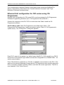
Ethernet Unit configuration for CS1-series using CXProgrammer
Ethernet Unit configuration for CS1-series PLCs can be processed by CX-Programmer
Windows Programming Software (see “CX-Programmer Users Manual”).
Connect the computer to the PLC CPU unit with Host Link Cable. Install the CXProgrammer software.
Set IP Address table. Start CX-Programmer (from Start menu: Start/.../CXProgrammer/CX-Programmer). Create new project (option "New" in CX-Programmer's
system menu). The "Change PLC" dialog box appears.
Enter PLC's name in the project (e.g. default name NewPLC1), PLC's model (e.g. CS1G)
and set the communication type used to access the configured PLC (SYSMAC WAY - for
serial communication).
Press "Work Online" pushbutton (or Ctrl+W) to establish communication to the PLC. (The
same can be done the following: in treeview (on CX-Programmer main window) select the
PLC (in example "NewPLC1(CS1G) Offline") and click the mouse right button. The PLC's
menu appears. Click "Work Online".)
OMRONETH Communication Server Ver 2.x User Manual Rev 1.12
1701XM112
Klinkmann Automation OMRONETH Communication Server
8
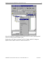
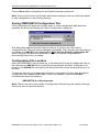
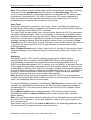
When CX-Programmer establishes communication with PLC, select "Operating Mode"
(from PLC's menu) and set "Program" mode.
Double-click on "IO Table" in treeview. The "PLC IO Table - NewPLC1" dialog box
appears. Select "Options" and click "Transfer from the PLC":
OMRONETH Communication Server Ver 2.x User Manual Rev 1.12
1701XM112
Klinkmann Automation OMRONETH Communication Server
9
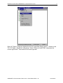
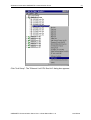
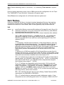
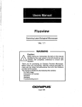
When IO Table is received, display the slot list under Main Rack (press "+" button in the
"PLC IO Table - NewPLC1" dialog box). Select "Ethernet Unit(ET)(0)" and press the
mouse right button. The Ethernet Unit menu appears:
OMRONETH Communication Server Ver 2.x User Manual Rev 1.12
1701XM112
Klinkmann Automation OMRONETH Communication Server
10
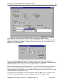
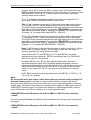
Click "Unit Setup". The "Ethernet Unit CPU Bus Unit" dialog box appears:
OMRONETH Communication Server Ver 2.x User Manual Rev 1.12
1701XM112
Klinkmann Automation OMRONETH Communication Server
11
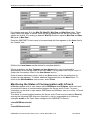
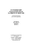
Enter Address Conversion type, FINS UDP port number and Sub-net Mask.
Edit the IP Address Table: the computer where OMRONETH Server is running must be
added to the IP Address Table. To add it, press "Insert" button. The "Insert Router's IP
Address" dialog box appears:
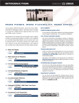
Enter the Node Number (in example 55) matching to the last octet in IP Address of
computer where OMRONETH Server is running. Enter the IP Address of computer where
OMRONETH Server is running (in example 195.2.103.55). Press "Ok".
Insert the Node Number and IP Address of PLC. (In case of CS1-series PLCs the Node
Number must match with settings on the rotary switch on the front side of Ethernet
communication unit, IP Address – must match with settings of rotary switches on the back
side of Ethernet communication unit).
To complete the configuration: from the "Ethernet Unit CPU Bus Unit" (or from the "PLC
IO Table - NewPLC1") dialog box select "Options" and click "Transfer to PLC".
OMRONETH Communication Server Ver 2.x User Manual Rev 1.12
1701XM112
Klinkmann Automation OMRONETH Communication Server
12
Example program for sending “unsolicited” data from PLC
The PLC example program presented in Plcprg.cxp project incorporates the SEND(090)
instruction for transferring unsolicited data from PLC to the OMRONETH Server (for
programming details see SYSMAC CS1 Series CS1W-ETN01 Ethernet Unit OPERATION
MANUAL, section 5).
The program transfers 10 words of data from DM10 (notation in ladder diagram - D00010)
from the PLC to the OMRONETH Server (into address DM500). The computer where
OMRONETH Server is running has the IP Address: 195.2.103.55 and the destination
node number is assigned to 55 (37 in hex).
Comments on example program ladder diagram:
(0) Periodically (once per second) the execution condition flag CIO 000000 turns ON.
Note: There can be different logic to turn ON execution condition flag in real
application.
(1) If the Communication Port Enabled Flag for port 7 is ON, the send execution program
will start when the execution condition flag CIO 000000 turns ON. Input CIO 120000
remains ON from the start of SEND execution until completion. Note: The CS1-series
CPU Unit’s Communication Port Enabled Flags are allocated the following way - in Word
A202: Bit 0 – is associated with Port 0, Bit 1 – is associated with Port 1, … , Bit 7 – is
associated with Port 7. Bit’s status OFF - means execution enabled, ON – means
execution disabled.
(2) Control data (DM0, DM1, … DM4) creation
Word
D0000
D0001
Contents
00 0A
00 00
D0002
37 00
D0003
87 05
D0004
00 64
Meaning
Number of send words = 10
Destination network number = 0 (local
network)
Destination node number = 55 (37 hex)
Destination unit address = 0
Response not required
Communication port No = 7
Number of retries = 5
Response monitor time = 10 s
Ten words with data from DM10 from PLC are sent to DM500 onwards on the local
network, node number 55, unit address 0 (the computer where OMRONETH Server is
running) – to receive all these data the items with addresses DM500…DM509 can be
correspondingly activated for OMRONETH Server.
(3) Reset the Input creation.
(4) Turn ON error information flag CIO 001300 if error happens. In this case CIO 001300
is not mandatory; any other flag may be used. Note: The CS1-series CPU Unit’s
Communication Port Error Flags are allocated the following - in Word A219: Bit 0 – is
associated with Port 0, Bit 1 – is associated with Port 1, … , Bit 7 – is associated with Port
7. Bit’s status OFF - means Normal completion, ON – means Abnormal completion.
OMRONETH Communication Server Ver 2.x User Manual Rev 1.12
1701XM112
Klinkmann Automation OMRONETH Communication Server
13
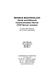
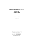
(5) The end of example program.
The example program ladder diagram is following:
OMRONETH Communication Server Ver 2.x User Manual Rev 1.12
1701XM112
Klinkmann Automation OMRONETH Communication Server
14
Configuring the OMRONETH Server
After the OMRONETH Server is initially installed, a little of configuration is required.
Configuring the Server automatically creates an OMRONETH.CFG file that holds all of the
topics (nodes) definitions entered, as well as the communication port configurations. This
file will be placed automatically in the same directory in which OMRONETH is located
unless the path where the configuration file will be placed is specified via the
/Configure/Server Settings... command.
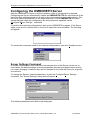
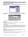
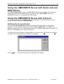
To perform the required configurations, start up the OMRONETH program. If the Server
starts up as an icon, double-click on the icon to open the server's window. The following
will appear:
To access the commands used for the various configurations, open the /Configure menu:
Server Settings Command
A number of parameters that control the internal operation of the Server can be set. In
most cases, the default settings for these parameters provide good performance and do
not require changing. However, they can be changed to fine-tune the Server for a specific
environment.
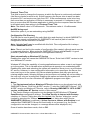
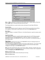
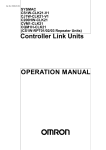
To change the Server's internal parameters, invoke the Configure/Server Settings...
command. The "Server Settings" dialog box will appear:
The following describes each field in this dialog box:
OMRONETH Communication Server Ver 2.x User Manual Rev 1.12
1701XM112
Klinkmann Automation OMRONETH Communication Server
15
Protocol Timer Tick
This field is used to change the frequency at which the Server is continuously activated
(the Server checks for work to do). At this frequency the Server tries to send one data
request to PLC and receive one reply from PLC. If the send/response cycle is too long
then more than one activation of Server is necessary to process it. If computer is very
busy or some other MS Windows application is taking over the computer then the Server
is activated rarely than setting in the Protocol Timer Tick.
Note: The default value is 50 milliseconds. The minimum value is 10 milliseconds.
NetDDE being used
Select this option if you are networking using NetDDE.
Configuration File Directory
The first field is used to specify the path (disk drive and directory) in which OMRONETH
will save its current configuration file. OMRONETH will use this path to load the
configuration file the next time it is started.
Note: Only the "path" may be modified with this field. The configuration file is always
named OMRONETH.CFG.
Note: There is no limit to the number of configuration files created, although each must be
in a separate directory. When using the OMRONETH Server with InTouch, it is good
practice to place the configuration file in the application directory.
Start automatically as Windows NT Service
Enabling this option will cause the OMRONETH Server “Suite Link & DDE” version to start
as a Windows NT service.
Windows NT offers the capability of running applications even when a user is not logged
on to the system. This is valuable when systems must operate in an unattended mode.
Enabling this option and rebooting the system will cause the Server to run as a Windows
NT service. However, to view configuration information or to reconfigure the Server, the
user must log on to the system. Any Server related problems that may arise such as
missing adapter cards, licensing failures or device drivers not loading will not be visible to
the user until a log on is performed. Disabling this option and rebooting the system will
cause the Server to run as a Windows NT application program once again.
Notes:
1. The Start automatically as Windows NT Service feature can be activated only with
OMRONETH Server “Suite Link & DDE” version. To start the OMRONETH Server “OPC
& DDE” version as Windows NT Service, refer to Running OMRONETH “OPC & DDE”
version as Windows NT Service section of this manual.
2. The Service Startup configuration can be changed by MS Windows NT Control
Panel/Services configuration dialogs. The Allow Service to Interact with Desktop
checkbox in “Service” dialog box must be checked (the “Service” dialog box can be
invoked by pressing the “Startup” button on “Services” dialog box when Service
OMRONETH_IOServer is selected). If Allow Service to Interact with Desktop is not
selected then OMRONETH Server full functionality is not ensured (e.g. the Server
configuration can not be changed, no message boxes will be displayed, etc.).
Once all entries have been made, click on OK.
OMRONETH Communication Server Ver 2.x User Manual Rev 1.12
1701XM112
Klinkmann Automation OMRONETH Communication Server
16
Socket Definition Command
To configure the Socket used for communications with OMRON Controller, invoke the
/Configure/Socket Definition... command. The "OMRONETH Socket Settings" first dialog
box will appear:
To modify or examine an existing Socket, select the topic name and click on Modify. To
define a new Socket, click on New. The "OMRONETH Socket Settings" secnd dialog box
will appear:
The following describes each dialog field in this dialog box:
Socket Name
Enter the Socket name and later use it in Topic Definition. Only one Socket with same
Internet Address and Port Number can be defined.
Internet Address
Enter the Computer Internet Address (IP Address) if it has more than one. If there is only
one Internet Address for computer then Use Default Address can be checked to use this
IP Address. If Computer is multi-homed (more than one Internet Address used) and Use
Default Address is checked then it is impossible to know which IP Address must be
used.
Port Number
Enter the UDP Port Number used for communications with OMRON Controllers. The Port
Number must much the Port Number configured in the OMRON Controller.
Note: The default port number is 9600.
Once all entries have been made, click on OK to process the configuration for the Socket.
The "OMRONETH Socket Settings" dialog box will appear again.
OMRONETH Communication Server Ver 2.x User Manual Rev 1.12
1701XM112
Klinkmann Automation OMRONETH Communication Server
17
Click on Done when configuration for all Sockets has been performed.
Note: If this is the first time the Sockets have been configured, the user will be prompted
to save configuration to an existing directory.
Saving OMRONETH Configuration File
If the configuration file does not currently exist, or a new configuration path has been
specified, the Server will display the "Save Configuration" dialog box:
This dialog box displays the path where the Server is going to save the current
configuration file. The path may be changed if necessary. Also, the path can optionally be
recorded in the WIN.INI file by selecting the "Make this the default configuration file"
option. Doing so will allow the OMRONETH Server to find the configuration file
automatically each time it is started.
Configuration File Location
When the OMRONETH Server starts up, it first attempts to locate its configuration file by,
first checking the WIN.INI file for a path that was previously specified. If the path is not
present in the WIN.INI file, the Server will assume that the current working directory is to
be used.
To start the Server from an application directory configuration file other than the default
configuration file a special switch (/d:) is used. For example, invoke the File/Run
command and enter the following:
OMRONETH /d:c:\directoryname
Note: There is no limit to the number of configuration files that may be created, although
each must be in a separate directory.
OMRONETH Communication Server Ver 2.x User Manual Rev 1.12
1701XM112
Klinkmann Automation OMRONETH Communication Server
18
Topic Definition Command
The user provides each node (OMRON PLC) with an arbitrary name that is used as the
Topic Name for all references to the node.
The following steps are taken to define the topics (OMRON PLCs) to be accessed from
OMRONETH Server:
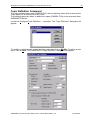
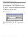
Invoke the Configure/Topic Definition… command. The "Topic Definition" dialog box will
appear:
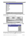
To modify an existing topic, select the topic name and click on Modify. To define a new
topic, click on New. The "OMRONETH Topic Definition" dialog box will appear:
OMRONETH Communication Server Ver 2.x User Manual Rev 1.12
1701XM112
Klinkmann Automation OMRONETH Communication Server
19
Topic Name
Enter the Topic Name.
Note: If using InTouch, the same Topic Name is to be entered in the "Add Access Name"
dialog box described in the Using the OMRONETH Server with InTouch section.
Socket
Select the Socket to associate it with the topic. Additional topics (OMRON PLCs) may be
associated with the same Socket at a later time.
Note: There can be several OMRON PLCs connected to the same Socket - in this case
all these PLCs must have the Controller Port Number (see below) same as Port
Number configured for this Socket (at Socket Definition Command…).
Computer Node Address
Enter the Computer node address. Each unit in the network must have its own unique
node address between 1 and 126 (between 1 and 62 when communicate with Controller
in the SYSMAC LINK Network). Care should be taken to select a node address that will
not conflict with other devices in the system.
Note: The Computer Node Address must match with the fourth byte (octet) of the
computer Internet Address specified for this topic’s Socket in the "OMRONETH Socket
Settings" second dialog box.
Computer Network Address
Enter the Local Network Address (the unique network address between 1 and 127 is
assigned to each network in the system). The entered value must be consistent with the
network address assigned in the routing tables. When communicate only with nodes in
the local network, you can set this Address to zero.
Controller Node Address
Enter the value in the Node Address field. Each Controller in the network must have its
own unique node address between 1 and 126 (between 1 and 62 when communicate with
Controller in the SYSMAC LINK Network). Care should be taken to select a node address
that will not conflict with other devices in the system.
Note: If destination node is OMRON PLC with Ethernet Unit installed, then Controller
Node Address must be configured according the following rules:
- if automatic conversion of Ethernet Unit’s IP address is used (also the node number
setting rotary switch on the front panel of the Ethernet Unit is used), then Controller
Node Address must be equal with the fourth byte (octet) of local IP address of Ethernet
Unit;
- if automatic conversion of Ethernet Unit’s IP address is not used (IP Address Table is
used), then Controller Node Address must be equal with the Node number configured
in the Ethernet Unit’s IP Address Table.
Controller Network Address
Enter the value in the Network Address field (the unique network address between 1 and
127 is assigned to each network in the system). When communicate with a node on
another (remote) network, the entered value must be consistent with the network address
assigned in the routing tables. Computer Network Address in this case must be nonzero. The network address of 0 indicates the local network.
OMRONETH Communication Server Ver 2.x User Manual Rev 1.12
1701XM112
Klinkmann Automation OMRONETH Communication Server
20
See the appropriate Ethernet Unit manual for additional information on Node and
Network Addresses.
Controller type
Select the Controller type. The available types are C-series, C200H-series (models
C200HX, C200HG and C200HE), CS1-series (this selection include also CJ1-series) and
CV-series. For CV-series Controller select the model type. To select Controller model
type, click on the combo box button and make your choice from the list.
Controller Internet Address
Enter the Controller Internet Address (IP Address) to communicate with. The Controller
Internet Address must match with IP address configured at corresponding Ethernet Unit
system setup (see the appropriate Ethernet Unit manual for details).
Controller Port Number
Enter the UDP Port Number used for communications with this OMRON Controller. The
Port Number must much with the Port Number set in the OMRON Controller by
appropriate Ethernet Unit configuration software.
Note: The default port number is 9600.
Update Interval
Set the Update Interval field to indicate the frequency the items/points on this topic
(OMRON PLC) must be read (polled); at this frequency all topic messages will be sent to
the network and replies must be received and processed. The value of zero indicates that
Server does not process data reeding messages (does not poll data) on this topic. At the
same time write commands will be still executed (new values written to PLC) and
unsolicited data from PLC will be received.
Note: By setting Update Interval value to 0, you configure a general topic quite similar to
the “slave” topic (see the Slave Topic option in this chapter later), which can be created
for unsolicited data processing. These two topic types differ in communication Status item
(see chapter Monitoring and Controlling Communication with a PLC) processing
principles. The “slave” topic periodically checks Communication Status with a PLC by
processing a special, application independent, message. So, communication Status item
of “slave” topic indeed indicates, whether communication fails or is successful, while
Status item value of a general topic with Update Interval=0 usually will be equal to 1 and
can hardly indicate real communication state.
Reply Timeout
Enter the amount of time (in seconds) nodes will be given to reply to commands from the
Server.
Note: The default value of 3 seconds should be sufficient for most configurations.
Message Type
Select Long Message if the Controller is directly connected to Ethernet or Controller is
connected through SYSMAC NET to other Controller, which is connected to Ethernet
directly.
Select Short Message if the Controller is connected through SYSMAC LINK to other
Controller that is connected to Ethernet directly.
OMRONETH Communication Server Ver 2.x User Manual Rev 1.12
1701XM112
Klinkmann Automation OMRONETH Communication Server
21
Note: The maximum amount of data which can be received by one message is following:
1986 bytes in one Long Message and 538 bytes in one Short Message. The real
amount of data received by one message depends on addresses of PLC memory areas
requested by client application. The using of consecutive PLC memory addresses is
highly recommended to decrease the total amount of messages sent to PLC(s) and
correspondingly to increase the performance of the Server.
Slave Topic
Check this checkbutton to create the “slave” topic. “Slave” topic does not prepare and
process general data reeding messages but is created to receive and process unsolicited
data. The writing of new values to PLC is possible.
The “slave” topic can periodically check communication Status with a PLC by processing
the special reeding message. There is not necessary to activate any item/point in client
application to activate such message processing. Simply set the Update Interval field of
this topic to non-zero value, indicating the frequency the communication Status checking
message must be processed. Enter the sufficient amount of time (in seconds) in Reply
Timeout field a PLC will be given to reply. The topic’s communication Status will be set as
1 only while the Server gets from a PLC a right response to communication Status
checking message.
Note: If Update Interval value of “slave” topic is set to 0, then the Communication Status
checking message is not created and value of communication Status item of topic is not
reliable.
Watchdog
Watchdog is usefull, if PLC internal program needs to check, whether there is
communication with a computer (running OMRONETH Server and application) or not.
With Watchdog activated the Server periodically writes some predefined value (e.g.
65535) into predefined address in PLC’s memory (e.g. into DM458). At the same time the
PLC program must periodically check the value in this memory address. If value is equal
to Watchdog’s predefined value, then PLC’s program considers communication Status as
Good and resets test address to different (non-predefined) value, e.g. to 0. (It will allow to
program to check communication state the next time.) If value differs from predefined,
then PLC’s program considers communication Status as Bad.
Note: Because of time synchronizing problems with PLC and PC it is recommended to
consider the communication Status as Bad only after few consecutive test value mismatch
cases, not immediately after the first mismatch.
To activate Watchdog processing - set Watchdog Time Interval to non-zero value. Value
entered in this field indicates the frequency the Server forwards Watchdog message to
corresponding PLC. This value must be equal to time interval the PLC program checks
the test address.
Enter Address to Write field to indicate address in PLCs memory that is used as
Watchdog test address. Address to Write must be valid item/point name (see Item
Names section.)
Note: Use only Word memory areas for Watchdog. Do not take addresses not presented
on current PLC configuration. Do not take addresses, used as PLC system areas or in
PLC’s program logic.
Enter integer from 0 to 65535 into Value to Write field to set Watchdog predefined value.
The same value PLC program expects to see in test area.
OMRONETH Communication Server Ver 2.x User Manual Rev 1.12
1701XM112
Klinkmann Automation OMRONETH Communication Server
22
Note: Default Watchdog state is “non-active”, it is, Watchdog Time Interval is equal to
zero.
Once all entries have been made, click on OK to process the configuration for the Topic.
The "OMRONETH Topic Definition" dialog box will appear again.
Select Done when configuration for all Sockets has been performed.
Item Names
Within the OMRONETH Server, item/point naming depends on Memory Area naming
conventions of Omron PLCs and possible read or write FINS commands. The Server
supports the fixed set of item names, each of them generally may be described as:
PnS
where n PS-
specifies the Memory area word/bit address of the specific word, flag or bit;
optionally used prefix, one or two characters before Memory area address,
and designates the type of Memory area;
optionally used suffix (suffixes), one, two or three characters after address:
".b" or ".bb" (where b can be 0…9 and bb can be 00…15) indicates the
Discrete bit inside the 16-bit Integer Memory area; for example, both
DM100.5 and DM100.05 are valid item names specifying bit 5 from PLC
address DM100.
Notes:
1. If necessary, the Discrete bit inside the 16-bit Integer Memory area can
be specified also without decimal point “.” by adding bit address (always 2
digits) after Memory area word address (word address must include all
preceding zeroes necessary for this PLC type); for example, for CS1 series
PLCs the valid item name to specify bit 5 from PLC address DM100 is
DM0010005 (as max. DM address for CS1 series PLCs is 32767, see
below).
2. As there is no FINS command for 16-bit Integer Memory area direct bit
writing to Omron PLCs, to write the bit value, the Server at first reads a word
(including the corresponding bit) from the PLC and then according to new bit
value this received word is modified and written back to PLC.
"S" or "s" indicates the 16-bit value received from PLC will be interpreted as
signed integer, e.g. DM100S (value range -32768 ... 32767); corresponding
item without suffix "S"("s") (e.g. DM100) will be interpreted as unsigned
short integer (value range 0 ... 65535).
"L" or "l" indicates two sequential words (consecutive 16-bit words with
addresses n and n+1) will be interpreted as one 32-bit signed value (value
range -2147483648... 2147483647); for example, if DM100 (lower word)
contains 1345 hex and DM101 (higher word) contains 2467 in hex then
DM100L will contain 610734917. Suffix "L"("l") can be used only with items,
indicating memory areas word contents.
"B" or "b" indicates that item value is set for Binary Coded Decimal (BCD)
transmission (e.g.DM100B or DM100LB).
"R" or "r" indicates that two sequential words (addresses n and n+1) are
interpreted as one real floating point value. For example, if DM0 in the PLC
OMRONETH Communication Server Ver 2.x User Manual Rev 1.12
1701XM112
Klinkmann Automation OMRONETH Communication Server
23
contains value 00 00 (hex) and DM1 contains value 3F 00 (hex) then item
DM0R is interpreted as real floating point item with value 0.5 (got from areas
DM0 and DM1). Suffix "R" ("r") can be used only with items, indicating
memory areas word contents.
"F" or "f" indicates forced status of word, flag or bit (not supported for Cseries and C200HX/C200HG/C200HE Omron PLCs).
"Mx" or "mx" indicates consecutive 16-bit words (block size x can be from 1
to 70 words) in a PLC can be interpreted as a string of ASCII characters.
The ASCII string is stored/retrieved from the high-order byte to the low-order
byte within each word address. For example, DM1000M20 is interpreted as
Data Memory area ASCII string, starting from address 1000 and with length
20 words, i.e. it occupies DM area DM1000…DM1019.
"Tx" or "tx" indicates consecutive block of bytes (block size x can be from 1
to 140 bytes) in a PLC can be interpreted as a string of ASCII characters.
The ASCII string is stored/retrieved from the high-order byte to the low-order
byte within each word address. For example, DM1000T20 is interpreted as
Data Memory area ASCII string, starting from address 1000 and with length
20 bytes, i.e. it occupies DM area DM1000…DM1009.
Note: If ASCII string is shorter than the range of memory specified, it will be
padded with '\0' (binary zeroes). If the string is longer than the range of
memory specified, the string will be truncated.
If two suffixes ("F"("f") and "B"("b") or "L"("l") and "B"("b")) are used
simultaneously then character "B"("b") must be the last (e.g. DM100LB).
BCD is not valid for forced words.
If suffixes "B"("b") and "S"("s") are used simultaneously, the Server
indicates item/point name error. Signed/unsigned designation does not
affect value interpretation for bits and forced words, yet the Server does not
indicate item/point name error if suffix "S" or "s" is used for bits or forced
words. In any case suffix "S" ("s") must be the last character in the item
name.
Suffix “R"("r") cannot be used simultaneously with "B"("b") or "S"("s") or "L"
("l") or "F" ("f") suffixes.
Note!
Do not operate with item names, which have addresses outside really existing PLC
data and memory area! It will lead to communication failures, because the Server
recognizes item name error only if item name goes out of range represented in the item
names table. Usually the information like following will be logged to WWLogger and/or to
OMRONETH internal logger if some item with address in inaccessible memory area is
used ("Parameter error: the first address is in an inaccessible area"):
/OMRONETH/Received Response Code Error (MRC:11 SRC:03) from controller
“node9”
For non-existing Extended Data Memory Area addresses the message like following will
be logged:
/OMRONETH/Received Response Code Error (MRC:11 SRC:01) from controller
“node9”
OMRONETH Communication Server Ver 2.x User Manual Rev 1.12
1701XM112
Klinkmann Automation OMRONETH Communication Server
24
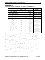
C-series PLCs
The following table lists the supported item names for the C-series PLCs:
Memory area
Input/Output register area
CIO (Bit status)
Input/Output register area
CIO (Word contents)
Latching Relay area
(Bit status)
Latching Relay area
(Word contents)
Holding Relay area
(Bit status)
Holding Relay area
(Word contents)
Auxiliary Relay area
(Bit status)
Auxiliary Relay area
(Word contents)
Completion flags for
Timers/Counters
Present Values for
Timers/Counters
Data Memory area
Item
name
Tag
Type
Discrete
Integer
LR
Discrete
LR
Integer
HR
Discrete
HR
Integer
AR
Discrete
AR
Integer
TC
Discrete
PV
Integer
DM
Integer
Range
00000...
51115(**)
0...
511(**)
LR0000...
LR6315
LR0...
LR63
HR0000...
HR9915
HR0...
HR99
AR0000...
AR2715
AR0...
AR27
TC0...
TC511
PV0...
PV511
DM0...
DM9999
Value
Range (*)
0, 1
0...65535
(-32768...32767)
0, 1
0...65535
(-32768...32767)
0, 1
0...65535
(-32768...32767)
0, 1
0...65535
(-32768...32767)
0, 1
0...65535
(-32768...32767)
0...65535
(-32768...32767)
Point names, corresponding to Input/Output register area CIO, are without prefix.
(*) Value range 0...65535 - for unsigned integers (item/point without suffix "S" ("s"));
value range -32768...32767 - for signed integers (item/point with suffix "S" ("s")).
(**) Represented memory area range is for C200HS type controller. For models C200H,
C1000H and C2000H - accessible memory area ranges are 00000...25515 for Discrete
items and 000...255 for Integer items.
Each word/bit address n in the item name specifies a specific bit or word. If item
corresponds to separate Bit of CIO, LR, HR or AR areas, the rightmost two digits of the
address specify bit 00 to 15.
The word address in this case is specified by the leftmost three digits (for CIO area items)
or the leftmost two digits (for LR, HR or AR items). Therefore every item name
representing Bit status must contain at least 5 digits (for CIO area items) or 4 digits (for
LR, HR and AR items). If necessary, item name can contain leading zeroes.
Item name, representing Word contents, must contain at least 1 digit.
OMRONETH Communication Server Ver 2.x User Manual Rev 1.12
1701XM112
Klinkmann Automation OMRONETH Communication Server
25
Present Values for Timers/Counters (PV) and Data Memory (DM) areas item names also
contain at least 1 digit; bit number in this case is not specified.
Note: All C-Series item types are Read/Write, except Completion flags for
Timers/Counters, which type is Read Only.
The following examples show the correct format for item names for C-series PLCs:
00201 - CIO area (Bit status), word address 2, bit number 1;
211
- CIO area (Word contents), word address 211;
LR6210 - Latching Relay area (Bit status), word address 62, bit number 10;
DM21 - Data Memory area (Word contents), word address 21.
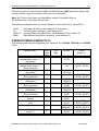
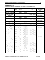
C200HX/C200HG/C200HE PLCs
The following table lists the supported item names for the C200HX, C200HG and C200HE
PLCs:
Memory area
Internal Relay Area 1, 2
Special Relay Area 1, 2
(Bit status)
Internal Relay Area 1, 2
Special Relay Area 1, 2
(Word contents)
Link Relay Area
(Bit status)
Link Relay Area
(Word contents)
Holding Relay Area
(Bit status)
Holding Relay Area
(Word contents)
Auxiliary Relay Area
(Bit status)
Auxiliary Relay Area
(Word contents)
Timer/Counter Area
(Status)
Timer/Counter Area
(PV)
Data Memory Area
Extended Data Memory
Area(***)
Tag
Type
Range
Value
Range (*)
Discrete
00000...
51115
0, 1
Integer
0...
511
0...65535
(-32768...32767)
LR
Discrete
0, 1
LR
Integer
LR0000...
LR6315
LR0... LR63
HR
Discrete
HR
Integer
AR
Discrete
AR
Integer
TC
Discrete
PV
Integer
DM
Integer
E
Integer
Item
name
prefix
OMRONETH Communication Server Ver 2.x User Manual Rev 1.12
HR0000...
HR9915
HR0...
HR99
AR0000...
AR2715
AR0...
AR27
TC0...
TC511
PV0...
PV511
DM0...
DM9999(**)
E0...
E6143
0...65535
(-32768...32767)
0, 1
0...65535
(-32768...32767)
0, 1
0...65535
(-32768...32767)
0, 1
0...65535
(-32768...32767)
0...65535
(-32768...32767)
0...65535
(-32768...32767)
1701XM112
Klinkmann Automation OMRONETH Communication Server
26
Point names, corresponding to Internal Relay Areas 1 and 2 and Special Relay Areas 1
and 2, are without prefix.
(*) Value range 0...65535 - for unsigned integers (item/point name without suffix "S" ("s"));
value range -32768...32767 - for signed integers (item/point name with suffix "S" ("s")).
(**) Memory area range DM7000…DM9999 is supported only if Expansion DM Area is
allocated on the PLC.
(***) Current bank only (Memory Area code 98).
Each word/bit address n in the item name specifies a specific bit or word. If item
corresponds to separate Bit of LR, HR, AR or Internal/Special Relay Area, the rightmost
two digits of the address specify bit 00 to 15.
The word address in this case is specified by the leftmost three digits (for
Internal/Special Relay Area) or the leftmost two digits (for LR, HR or AR items).
Therefore every item name, representing Bit status, must contain at least 5 digits (for
Internal/Special Relay Area) or 4 digits (for LR, HR and AR items). If necessary, item
name can contain leading zeroes. The item name, representing Word contents, must
contain at least 1 digit.
Present Values for Timers/Counters (PV), Data Memory (DM) and Extended Data
Memory (E) areas item names also contain at least 1 digit; bit number in this case is not
specified.
Note: All C200HX, C200HG and C200HE item types are Read/Write, except Completion
flags for Timers/Counters, which type is Read Only.
The following examples show the correct format for item names for C200HX, C200HG
and C200HE PLCs:
00201 257
LR6210 DM21 -
Internal Relay Area (Bit status), word address 2, bit number 1;
Special Relay Area (Word contents), word address 257;
Link Relay Area (Bit status), word address 62, bit number 10;
Data Memory Area (Word contents), word address 21.
OMRONETH Communication Server Ver 2.x User Manual Rev 1.12
1701XM112
Klinkmann Automation OMRONETH Communication Server
27
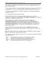
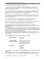
CS1/CJ1-series PLCs
The following table lists the supported item names for the CS1-series and CJ1-series
PLCs:
Memory area
CIO Area
(Bits)
CIO Area
(Words)
Work Area
(Bits)
Work Area
(Words)
Holding Area
(Bits)
Holding Area
(Words)
Auxiliary Area
(Bits) (**)
Auxiliary Area
(Words) (**)
TR (Temporary Relay)
Area
Data Memory (DM)
Area
Extended Data Memory
(EM) Area (***)
Timer Completion
Flags
Counter Completion
Flags
Timer PVs
Item
name
prefix
Tag
Type
Range
Value
Range (*)
Discrete
000000...
614315
0...
6143
W00000...
W51115
W0... W511
0, 1
Integer
W
Discrete
W
Integer
H
Discrete
H
Integer
A
Discrete
A
Integer
TR
Discrete
DM
Integer
E
Integer
T
Discrete
C
Discrete
PT
Integer
Counter PVs
PC
Integer
Index Registers
IR
Integer
Data Registers****
DR
Integer
H00000...
H51115
H0...
H511
A95915...
A959
A0...
A959
TR0...
TR15
DM0...
DM32767
E0...
E32767
T0...
T4095
C0...
C4095
PT0...
PT4095
PC0...
PC4095
IR0...
IR15
DR0...
DR15
0...65535
(-32768...32767)
0, 1
0...65535
(-32768...32767)
0, 1
0...65535
(-32768...32767)
0, 1
0...65535
(-32768...32767)
0, 1
0...65535
(-32768...32767)
0...65535
(-32768...32767)
0, 1
0, 1
0...65535
(-32768...32767)
0...65535
(-32768...32767)
0...65535
(-32768...32767)
0...65535
(-32768...32767)
Item names corresponding to CIO Area bits and words are without prefix.
(*) Value range 0...65535 - for unsigned integers (item/point name without suffix "S" ("s"));
value range -32768...32767 - for signed integers (item/point name with suffix "S" ("s")).
(**) Data can not be written to addresses A000…A447 in the Auxiliary Area.
OMRONETH Communication Server Ver 2.x User Manual Rev 1.12
1701XM112
Klinkmann Automation OMRONETH Communication Server
28
(***) Current bank only (Memory Area code 98).
(****) Not supported on CJ1 controllers.
Each word/bit address n in the item name specifies a specific bit or word. If item
corresponds to separate Bit of CIO, W, H and A areas, the rightmost two digits of the
address specify bit 00 to 15.
The word address in this case is specified by the leftmost four digits (for CIO area items)
or the leftmost three digits (for W, H or A items). Therefore every item name, representing
the Bit, must contain at least 6 digits (for CIO area items) or 5 digits (for W, H and A
items). If necessary, item name can contain leading zeroes. The item name, representing
Word contents for these areas, must contain at least 1 digit.
Temporary Relay (TR), Timer Completion Flags (T) and Counter Completion Flags (C)
areas item names also must contain at least 1 digit representing the bit address in the
memory area.
Data Memory (DM), Extended Data Memory (E), Timer PVs (PT), Counter PVs (PC),
Index Registers (IR) and Data Registers (DR) areas item names also contain at least 1
digit representing the word address in the memory area; bit number in this case is not
specified.
The following examples show the correct format for item names for CS1 PLCs:
00201 257
H6210 DM21 -
CIO Area (Bit), word address 2, bit number 1;
CIO Area (Word contents), word address 257;
Holding Area (Bit), word address 62, bit number 10;
Data Memory Area with word address 21.
OMRONETH Communication Server Ver 2.x User Manual Rev 1.12
1701XM112
Klinkmann Automation OMRONETH Communication Server
29
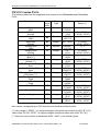
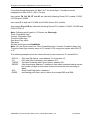
CV-series PLCs
The following table lists the supported item names for the CV-series PLCs:
Memory area
Input/Output register
area CIO (Bit status)
Input/Output register
area CIO (Word
contents)
Area G (Bit status)
Item
name
Tag
Type (*)
Range
Discrete/
Integer
Integer
000000...
255515
0... 2555
G00000...
G25515
G0... G255
A00000...
A51115
A0... A511
Area G (Word
contents)
G
Discrete/
Integer
Integer
Auxiliary Relay
area A (Bit status)
Auxiliary Relay
area A (Word cont.)
Timer Completion
flags TIM
Counter Completion
flags CNT
Timer Present Value
A
Discrete
A
Integer
T
PT
Discrete/
Integer
Discrete/
Integer
Integer
PC
Integer
DM
Integer
TN
SA
Discrete/
Integer
Integer
SS
Integer
ST
Integer
E
Integer
AC
Discrete
IR
Integer
T0...
T1023(**)
C0...
C1023(**)
PT0...
PT1023(**)
PC0...
PC1023(**)
DM0...
DM24575(**
*)
TN0...
TN1023(**)
SA0...
SA1023(**)
SS0...
SS1023(**)
ST0...
ST1023(**)
E0...
E32765
AC0...
AC2047
IR0...IR2
DR
Integer
DR0...DR2
Counter Present
Value
Data Memory area
Transition Area
flags
Step Area Flag
status
Step Area status
Step timer Present
Value
Expansion area
(Current bank)
Action Area Flag
status
Register Area
contents IR
Register Area
contents DR
G
C
OMRONETH Communication Server Ver 2.x User Manual Rev 1.12
Value Range
(****)
0, 1
0...65535
(-32768...32767)
0, 1
0...65535
(-32768...32767)
0, 1
Value Range
with Forced
Status
0, 1, 2, 3
-2147483648
...
2147483647
0, 1, 2, 3
-2147483648
...
2147483647
-
0...65535
(-32768...32767)
0, 1
0, 1, 2, 3
0, 1
0, 1, 2, 3
0...65535
(-32768...32767)
0...65535
(-32768...32767)
0...65535
(-32768...32767)
-
0, 1
0, 1, 2, 3
0, 1, 2, 3
-
0, 1, 2, 3
-
0...65535
(-32768...32767)
0...65535
(-32768...32767)
0, 1
-
0...65535
(-32768...32767)
0...65535
(-32768...32767)
-
-
-
1701XM112
Klinkmann Automation OMRONETH Communication Server
30
Item names corresponding to CIO area are without prefix.
(*) If two Tag Types ("Discrete/Integer") are given in the table for the same item, it
means, that item with unforced status has the first type (Discrete), but item with forced
status - the second type (Integer).
(**) Represented memory area ranges are for CV1000, CV2000 and CVM1-CPU11-E
type controllers. For CV500 and CVM1-CPU01-E - accessible memory area ranges are
00000...51115 for Discrete items and 0...511 for Integer items.
(***) Represented memory area ranges are for CV1000, CV2000 and CVM1-CPU11-E
type controllers. For CV500 and CVM1-CPU01-E - accessible memory area ranges are
0...8191 for Integer Items.
(****) Value range 0...65535 - for unsigned integers (item without suffix "S" ("s"));
value range -32768...32767 - for signed integers (item with suffix "S" ("s")).
If there are not represented values in the column "Value Range with Forced Status", the
Server does not support corresponding Memory area with forced status.
Each word/bit address n in the item name specifies a specific bit or word. If item
corresponds to separate Bit of G, A or CIO area, the rightmost two digits of the address
specify bit 00 to 15.
The word address in this case is specified by the leftmost four digits (for CIO area items)
or the leftmost three digits (for G or A items). Therefore every item name representing Bit
status, must contain at least 6 digits (for CIO area items) or 5 digits (for G and A items). If
necessary, item name can contain leading zeroes.
Item name, representing Word contents, must contain at least 1 digit. All item names,
except CIO area and G and A areas, also contain at least 1 digit; bit number in this case
is not specified.
The configuration of the various types of data can be as follows:
Flag or Bit Status
0: Bit is OFF;
1: Bit is ON;
Flag or Bit Status
with Forced Status
0: Bit is OFF but not Forced;
1: Bit is ON but not Forced;
2: Bit has been forced OFF;
3: Bit has been forced ON;
Step Status
0: INACTIVE;
1: HALT;
2: PAUSE;
3: EXECUTE;
Word Contents or Present Value PV with Unforced Status contains two Bytes: contents
of Bits 0 to 15.
Word Contents or Present Value PV with Forced Status contains four Bytes: the first
Byte - contents of Bits 0 to 7; the second Byte - contents of Bits 8 to 15; the third Byte OMRONETH Communication Server Ver 2.x User Manual Rev 1.12
1701XM112
Klinkmann Automation OMRONETH Communication Server
31
Forced/not forced designation for Bits 0 to 7; the fourth Byte - Forced/not forced
designation for Bits 8 to 15; (ON = Forced).
Item names TN, SA, SS, ST and AC are valid with following Omron PLC models: CV500,
CV1000 and CV2000.
Item name E is valid with CV1000 and CV2000 Omron PLC models.
Item names IR and DR are valid with following Omron PLC models: CV1000, CV2000 and
CVM1-CPU11-E.
Note: Following point types for CV-Series are Read only:
Timer Completion flags,
Counter Completion flags,
Transition Area flags,
Step Area Flag status,
Step Area.
All other point types are Read/Write.
Note: You can force values into Timer Completion flags, Counter Completion flags and
Transition Area flags memory areas of CV-series PLCs using point names with suffix "F"
or "f".
The following examples show the correct format for item names for CV-series PLCs:
002113 211
TN200F SS0007 -
AC6
DM3R -
CIO area (Bit status), word address 21, bit number 13;
CIO area (Word contents), word address 211;
Transition Area flag with Forced status, address 200;
Step Area status, address 7 (address in item name contains leading zeroes,
but number of digits in item name does not exceed the limit according to
table);
Action Area Flag status, address 6.
real floating point item, value is taken from words DM3 and DM4.
OMRONETH Communication Server Ver 2.x User Manual Rev 1.12
1701XM112
Klinkmann Automation OMRONETH Communication Server
32
Monitoring and Controlling Communication with a PLC
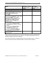
For each topic, there are following additional items offered by OMRONETH Server to
monitor and control the communication with PLC.
STATUS
For each topic, there is a built-in discrete item that indicates the state of communication
with PLC. The discrete item (STATUS) is set to 0 when communication fails and set to 1
when communication is successful.
From InTouch the state of communication may be read by defining an I/O Discrete
tagname and associating it with the topic configured for the PLC and using STATUS as
the item name.
From Excel, the status of the communication may be read by entering the following
formula in a cell:
=OMRONETH|topic!STATUS
UPDATEINTERVAL
The UPDATEINTERVAL item is an Integer type Read/Write item used to access the
currently set Update Interval (see Topic Definition Command section). It indicates the
current requested update interval (in milliseconds). The value of this item can be read
through DDE or Suite Link. Client can poke new values to this item. The range of valid
values is from 10 to 2147483647 milliseconds. The value of zero indicates that no items
on this topic are updated. The write commands are still executed (new values written to
PLC) if UPDATEINTERVAL value is 0.
Note: By poking a value of zero to the UPDATEINTERVAL item, a client can stop all
update activities on the corresponding topic without having to deactivate the items.
MAXINTERVAL
The MAXINTERVAL item is an Integer type Read Only item used to access the
measured maximum update interval (in milliseconds) of all items for the corresponding
topic for the last completed poll cycle. The range of valid values is from 0 to 2147483647
milliseconds.
The UPDATEINTERVAL and MAXINTERVAL items can be used to tune the
performance of communication.
ITEMCOUNT
The ITEMCOUNT item is an Integer type Read Only item used to access the number of
active items in the corresponding topic. The range of valid values is from 0 to
2147483647.
ERRORCOUNT
The ERRORCOUNT item is an Integer type Read Only item used to access the number
of active items with errors in the corresponding topic. The range of valid values is from 0
to 2147483647.
OMRONETH Communication Server Ver 2.x User Manual Rev 1.12
1701XM112
Klinkmann Automation OMRONETH Communication Server
33
ERRORITEMS
The ERRORITEMS item is an Integer type Read/Write (unique for each topic) used to
access the total number of items with invalid item names (these items are rejected by
Server). The ERRORITEMS value can be reseted by writing 0 to this item. The range of
valid values is from 0 to 2147483647.
WRITECOUNT
The WRITECOUNT item is an Integer type Read Only item used to access the number of
write commands (messages) waiting for execution. The range of valid values is from 0 to
2147483647.
For example, in following way the WRITECOUNT item can be used to avoid the
increasing of memory occupied by not executed write commands:
- activate the hot link with WRITECOUNT item and start to monitor it;
- activate new write command (by poking new value) only if value of WRITECOUNT
becomes equal to 0, e.g. all previous write commands are executed and memory
occupied by them is freed.
SUSPEND
Special Read/Write Discrete Item SUSPEND may be used to control the communication
with a separate topic. If application changes SUSPEND value from 0 to 1 then then
communication with topic is suspended. If SUSPEND value is changed back to 0 then
communication with this topic is resumed.
Note: If topic is suspended by setting SUSPEND value to 1, then Server rejects all new
write values to this topic, i.e. no new write messages are created after SUSPEND value
has changed from 0 to 1.
KEEPALIVE
For each Topic the special Integer Read/Write item KEEPALIVE can be activated. The
value of KEEPALIVE changes from 0 to 1 or from 1 to 0 at some timer interval (default is
10 seconds, this default value can be changed by adding special entry in WIN.INI file
[OMRONETH] section, see WIN.INI entries section later in this manual). This timer
interval can also be changed at run-time by writing any new value (equal to new timer
interval, in seconds) to KEEPALIVE item. After this writing the new timer interval will start,
but KEEPALIVE item value still will change from 0 to 1 and back. The KEEPALIVE item
can be used to create artificial delivery of new data from Server to client application if
needed (for example, if accessing to Omron PLCs from Wonderware IndustrialSQL
Server and if some time no new values are received from PLC).
OMRONETH Communication Server Ver 2.x User Manual Rev 1.12
1701XM112
Klinkmann Automation OMRONETH Communication Server
34
Using the OMRONETH Server with OPC Clients
The “OPC & DDE” version of OMRONETH Server is accessible from OPC Clients.
There are following general steps needed to access an OPC item from OMRONETH
Server:
1.
2.
3.
4.
Run OPC Client application and select the “OMRONETH OPC and DDE Server”
from the list of available OPC Servers. If OMRONETH Server currently is not
running, it will start automatically.
Create a new group (or topic if Wonderware OPCLink application is used).
If OPC Client supports the validating of items, validate the item before adding it.
Add the item. Depending on OPC Client it can be done in several different ways, for
example:
a) By entering separately the access path to topic name (valid topic name configured
in OMRONETH Topic definition) and separately the item name.
b) By entering the full path to item name in the format TopicName.ItemName
where TopicName is the valid topic name configured in OMRONETH Topic
definition.
c) By browsing the server address space.
By default the OMRONETH Server is installed and used as a local OPC Server - both
OPC Server and OPC Client reside on same computer. The OMRONETH Server can run
also as a remote OPC Server – in this case OPC Server and OPC Client are located on
separate computers. Accessing the remote OPC Server is same as for local OPC Server,
but some DCOM (Distributed COM) configuration is required before accessing the remote
OPC Server. The DCOM configuration must be done both on OPC Server and OPC
Client computers.
Configuring DCOM
To access OMRONETH Server as a remote OPC Server, it is necessary to install
OMRONETH Server on both (OPC Server and OPC Client) computers. Also the DCOM
must be configured on both computers.
After Server installation the System Administrator must configure DCOM by
Dcomcnfg.exe (or Dcomcnfg32.exe for Win9x) system tool. This utility is located in the
Windows system directory – e.g. in \WinNT\system32\ or \Win9x\system\.
Below is a simple example how to configure DCOM on NT Workstations for OPC Server
computer (computer name JohnB) and on OPC Client computer (computer name SteveL).
OMRONETH Communication Server Ver 2.x User Manual Rev 1.12
1701XM112
Klinkmann Automation OMRONETH Communication Server
Action
Remote OPC Server
Computer name –
JohnB
!
!
!
Install the OPC Server.
Run Dcomcnfg.exe
Invoke Default Properties and set
Default Authentication Level to (None),
Default Impersonation Level to
Impersonate.
Select OPC Server from Applications list
and click on the Properties… button. Click
on the Location tab, uncheck Run
application on this computer, check
Run application on the following
computer and browse the remote
computer JohnB.
!
Edit Security settings:
1) set the following custom access
permissions: NETWORK, SYSTEM,
SteveL;
2) set the following custom launch
permissions: INTERACTIVE,
SYSTEM, NETWORK, SteveL;
3) be sure the Default Configuration
Permissions contain SYSTEM.
!
Click on the Identity tab and select The
interactive user.
35
OPC Client
Computer name –
SteveL
!
!
!
!
Before starting a remote OPC Server, be sure the OPC Server computer and OPC Client
computer can access each other on the network. The “Remote Procedure Call” Service
should be started on OPC Server computer.
Now remote OPC Server is accessible for OPC Client on computer SteveL. To allow the
access to more OPC Clients, configure DCOM on each OPC Client computer.
OMRONETH Communication Server Ver 2.x User Manual Rev 1.12
1701XM112
Klinkmann Automation OMRONETH Communication Server
36
The following table contains most frequent errors when configuring DCOM.
Error message
DCOM not installed
Server execution failed
Class not registered
RPC server is unavailable
Interface not supported
Access is denied
Error 80070776
Catastrophic failure
Not enough storage
Possible reason
DCOM has not been installed
1) OPC Server can not be started
2) Identity for OPC server not properly configured
3) OPC Server is not located on a local hard disk
4) OPC Server path in registry is too long or uses LFN
(Long File Names)
5) DCOMCNFG Location is not set to Run on this
computer.
OPC Server has not been registered
1) Remote Procedure Call service is not running on the
OPC Server computer
2) Invalid computer name for remote OPC Server
3) Make sure TCP/IP is installed properly
1) Permission not granted to OPC Client
2) Guest account disabled
1) DCOM security not configured properly
2) OPC Server application not located on local hard disk
3) SYSTEM account in DCOMCNFG must have Access,
Launch and Configure privileges
Network error - TCP/IP has not been configured
properly
1) Trying to access an object before it is created
2) Unhandled exception is occurs on the OPC Server
SYSTEM account in DCOMCNFG must have Access,
Launch and Configure privileges
Running OMRONETH “OPC & DDE” version as Windows NT
Service
To install OMRONETH Server “OPC & DDE” version to run as Windows NT Service, the
OMRONETH Server must be started with command line parameter "/Service":
OMRONETH /Service
After this the “OMRONETH OPC & DDE Server” NT Service will be installed with Startup
type “Manual”. The Service Startup configuration can be changed by MS Windows NT
Control Panel/Services configuration dialog boxes. The Allow Service to Interact with
Desktop checkbox in “Service” dialog box must be checked (the “Service” dialog box can
be invoked by pressing the “Startup” button on “Services” dialog box when Service
OMRONETH OPC & DDE Server is selected). If Allow Service to Interact with
Desktop is not selected then OMRONETH Server full functionality is not ensured (e.g. the
Server configuration can not be changed, no message boxes will be displayed, etc.).
OMRONETH Communication Server Ver 2.x User Manual Rev 1.12
1701XM112
Klinkmann Automation OMRONETH Communication Server
37
To use OMRONETH Server “OPC & DDE” version as Windows NT Service you may need
to configure DCOM. For details of configuring DCOM refer to Configuring DCOM section
of this manual. If “OMRONETH OPC & DDE Server” NT Service will be accessed only
from local OPC clients (i.e. OMRONETH Server will not be used as a remote OPC
Server), then custom access and launch permissions “NETWORK” are not needed.
To uninstall “OMRONETH OPC & DDE Server” NT Service, at first the Service must be
stopped by Control Panel/Services/Stop and then OMRONETH Server must be started
manually with command line parameter "/DelService":
OMRONETH /DelService
After this the OMRONETH Server “OPC & DDE” version will be still registered and
accessible to OPC clients.
OMRONETH Communication Server Ver 2.x User Manual Rev 1.12
1701XM112
Klinkmann Automation OMRONETH Communication Server
38
Using OMRONETH with OPCLink Server
The Wonderware OPCLink I/O Server (hereafter referred to as “OPCLink”) is a Microsoft
Windows application program that acts as a communication protocol converter and allows
other Windows application programs access to data from local or remote OPC servers.
OPCLink connects to OPC servers, converts client commands to OPC protocol and
transfers data back to clients using DDE, FastDDE, or Suite Link protocols.
Please refer to Wonderware OPCLink Server and OPC Browser User’s Guide for
details how to install, start and use the OPCLink Server. The following information in this
section covers only the most important points about using “OPC & DDE” version of
OMRONETH Server with OPCLink Server.
OPCLink Topic Definition
The Topic Definition option from OPC Link Configure menu is used to create, modify, or
delete OPCLink topic definitions. If OPC Link will communicate with OMRONETH Server
then there must exist one or more topics defined for OMRONETH Server. There are
following important fields on the “OPCLink Topic Definition” dialog box:
Topic Name
Enter a unique name (e.g. PLC2) for the PLC in this field. If using InTouch then same
Topic Name is to be entered in the "Add Access Name" dialog box when defining the
Access Names for OPCLink Server in InTouch WindowMaker.
OPC Server Name
Select the name of the OPC server (OMRONETH.OPC_Server) that will be used by this
topic. The list box shows the registered OPC servers in the system.
OPC Path
Enter the name of the OPC path (e.g. node2.) used by this topic. This OPC path is the
first part of a full OPC item name string common to all items that will be used in this topic.
The available OPC paths for OMRONETH Server can be obtained by clicking on “Browse”
button (this allows to view the OMRONETH Server’s exposed address space).
Update Interval
Enter the frequency (in milliseconds) that the server will acquire data for the items/points
associated with this topic. If 0 (zero) is entered here, OPCLink will not gather data from
OMRONETH Server.
Browse
Clicking on this button initiates the browsing through exposed address space of
OMRONETH Server. All currently available item/point names (including data area names
and range of addresses) and names of pre-defined (additional) items will appear on
“Browse OPC items:” window in alphabetical order.
OMRONETH Communication Server Ver 2.x User Manual Rev 1.12
1701XM112
Klinkmann Automation OMRONETH Communication Server
39
Accesing OMRONETH Items via the OPCLink Server
The communication protocol addresses an element of data in a conversation that uses a
three-part naming convention that includes the application name, topic name and item
name. The following briefly describes each portion of this naming convention:
application name
The name of the Windows program (server) that will be accessing the data element. In
the case of data coming from or going to OMRONETH Server “OPC & DDE” version, the
application portion of the address is OPCLINK.
topic name
Meaningful names are configured to identify specific devices (PLCs). These names are
then used as the topic name in all conversations to that device (PLC). This must be same
name as Topic Name entered in the “OPCLink Topic Definition” dialog box, for example,
PLC2.
Note! You can define multiple topic names for the same PLC to poll different points at
different rates.
item name
A specific data element within the specified topic. The OPCLink Server item syntax
follows the following rules. The item names must start with:
d – discrete value
i – integer value
r – real value
m – message value
The item name added to the OPC path of the topic (without the heading type letter) must
give a fully qualified OPC item name for the OMRONETH Server. Some examples of
possible item names acceptable by OPCLink Server/OMRONETH Server connection:
d002113
discrete
CIO area (Bit status), word address 21, bit number 13;
iDM100
integer
Data Memory area word 100
rDM3R
real
real floating point item, value is taken from Data Memory area words DM3 and
DM4
OMRONETH Communication Server Ver 2.x User Manual Rev 1.12
1701XM112
Klinkmann Automation OMRONETH Communication Server
40
Using the OMRONETH Server with Suite Link and
DDE Clients
The “Suite Link & DDE” version of OMRONETH Server is accessible from Suite Link
clients (e.g. InTouch) and DDE clients (e.g. Excel). The “OPC & DDE” version of
OMRONETH Server is accessible from DDE clients.
Using the OMRONETH Server with InTouch
To access items/points on Omron PLCs from InTouch, the Access Names and Tag
names should be defined in WindowMaker.
Defining the Access Names
InTouch uses Access Names to reference real-time I/O data. Each Access Name
equates to an I/O address, which can contain a Node, Application, and Topic. In a
distributed application, I/O references can be set up as global addresses to a network I/O
Server or local addresses to a local I/O Server.
To define the Access Names in WindowMaker node invoke the /Special/Access Names...
command. The "Access Names" dialog box will appear.
Click on Add…. The "Add Access Name" Dialog Box will appear:
OMRONETH Communication Server Ver 2.x User Manual Rev 1.12
1701XM112
Klinkmann Automation OMRONETH Communication Server
41
Note: If Add is selected, this dialog box will be blank when it initially appears. Data has
been entered here to illustrate the entries that are made.
The following fields are required entries when entering an Access Name Definition:
Access Name
In the Access Name box type the name you want InTouch to use to this Access Name.
(For simplicity, use the same name that you will use for the Topic Name here.)
Node Name
If the data resides in a network I/O Server, in the Node Name box, type the remote node's
name.
Application Name
In the Application Name box, type the actual program name for the I/O Server program
from which the data values will be acquired. In case the values are coming from the
OMRONETH Server the OMRONETH is used. Do not enter the .exe extension portion of
the program name.
Topic Name
Enter the name defined for the topic in the OMRONETH Server to identify the topic the
OMRONETH Server will be accessing.
The Topic Name is an application-specific sub-group of data elements. In the case of data
coming from OMRONETH Server program, the topic name is the exact same name
configured for the topic in the OMRONETH Server.
Note: This will usually be the same as the "Access Name", although, if desired, they may
be different. However, it must be the same name used when the topics were configured in
section Configuring the OMRONETH Server.
Which protocol to use
Select the protocol (DDE or Suite Link) that you are using.
When to advise server
OMRONETH Communication Server Ver 2.x User Manual Rev 1.12
1701XM112
Klinkmann Automation OMRONETH Communication Server
42
Select Advise all items if you want the Server program to poll for all data whether or not
it is in visible windows, alarmed, logged, trended or used in a script. Selecting this option
will impact performance, therefore its use is not recommended.
Select Advise only active items if you want the Server program to poll only points in
visible windows and points that are alarmed, logged, trended or used in any script.
Click OK to accept the new Access Name and close the “Add Access Name” dialog box.
The “Access Names” dialog box will reappear displaying the new Access Name selected
in the list.
Click Close to close the “Access Names” dialog box.
Defining the Tag names
To define the Tag names associated with the new "Access Name", invoke the
/Special/Tagname Dictionary... command (in WindowMaker). The "Tagname Dictionary"
dialog box will appear:
Click on New and enter the Tag Name. (The tag name defined here is the name InTouch
will use. The OMRONETH Server does not see this name.)
Select the tag type by clicking on the Type:… button. The "Tag Types" dialog box will
appear:
OMRONETH Communication Server Ver 2.x User Manual Rev 1.12
1701XM112
Klinkmann Automation OMRONETH Communication Server
43
To access OMRONETH items, the type must be I/O Discrete, I/O Integer or I/O Real.
Select the Tag type.
The "Details" dialog box for the tag name will appear:
Select the Access Name for OMRONETH Server by clicking on the Access Name:…
button. The "Access Names" dialog box will appear:
Select the appropriate Access Name and click on Close. (If the Access Name has not
been defined as previously described, click on Add and define the Access Name now.)
The "Details" dialog box will appear displaying the selected Access Name:
OMRONETH Communication Server Ver 2.x User Manual Rev 1.12
1701XM112
Klinkmann Automation OMRONETH Communication Server
44
For integers and reals fill in the Min EU, Max EU, Min Raw and Max Raw fields. These
fields control the range of values, which will be accepted from the Server and how the
values are scaled. If no scaling is desired, Min EU should be equal to Min Raw and Max
EU equal to Max Raw.
Enter the OMRONETH item name to be associated with this tagname in the Item: field in
the "Details" box:
(Refer to the Item Names section below for complete details.)
Where applicable, the Use Tagname as Item Name option may be selected to
automatically enter the tag name in this field. Note: The tag name can only be used if it
follows the conventions listed in the Item Names section.
Once all entries have been made, click on the Save button (in the top dialog box) to
accept the new tagname. To define additional tagnames click on the New button. To
return to the WindowMaker main screen, select Close.
Monitoring the Status of Communication with InTouch
InTouch supports built-in topic names called DDEStatus and IOStatus, which are used
to monitor the status of communication between the Server and InTouch. For more
information on the built-in topic names DDEStatus and IOStatus, see your online “InTouch
User’s Guide”.
The status of communication between the Server and InTouch can be read into Excel by
entering the following DDE reference formula in a cell on a spreadsheet (in following
examples node2 is the Topic Name configured for OMRONETH Server):
=view|DDEStatus!node2
or
=view|IOStatus!node2
OMRONETH Communication Server Ver 2.x User Manual Rev 1.12
1701XM112
Klinkmann Automation OMRONETH Communication Server
45
Notes on Using Microsoft Excel
Data from OMRONETH topics (nodes) may be accessed from Excel spreadsheets. To do
so, enter a formula like the following into a cell on the spreadsheet.
=OMRONETH|topic!item
Sometimes, Excel requires the topic and/or item to be surrounded by apostrophes.
In the formula, topic must be replaced with one of the valid topic names defined during
the Server configuration process. Replace item with one of the valid item names
described in the Item Names section.
Reading Values into Excel Spreadsheets
Values may be read directly into Excel spreadsheets by entering a DDE formatted formula
into a cell, as shown in the following examples:
=OMRONETH|'node2'!'125515'
=OMRONETH|'node3'!'SA1000'
=OMRONETH|'node10'!'IR2'
Note: Refer to the Microsoft Excel manual for complete details on entering Remote
Reference formulas for cells.
Writing Values to OMRONETH Points
Values may be written to the Server from Microsoft Excel by creating an Excel macro that
uses the POKE command. The proper command is entered in Excel as follows:
channel=INITIATE("OMRONETH","topicname")
=POKE(channel,"itemname", Data_Reference)
=TERMINATE (channel)
=RETURN()
The following describes each of the above POKE macro statements:
channel=INITIATE("OMRONETH ","topicname")
Opens a channel to a specific topic name (defined in the Server) in an application with
name OMRONETH (the executable name less the .EXE) and assigns the number of that
opened channel to channel.
Note: By using the channel=INITIATE statement the word channel must be used in
the =POKE statement instead of the actual cell reference. The "applicationname"
and "topicname" portions of the formula must be enclosed in quotation marks.
=POKE(channel,"itemname", Data_Reference)
POKEs the value contained in the Data_Reference to the specified item name (actual
location in the Omron PLC) via the channel number returned by the previously executed
INITIATE function. Data_Reference is the row/column ID of the cell containing the data
value. For "itemname", use some of the valid item names specified like described in the
Item Names section.
OMRONETH Communication Server Ver 2.x User Manual Rev 1.12
1701XM112
Klinkmann Automation OMRONETH Communication Server
46
=TERMINATE(channel)
Closes the channel at the end of the macro. Some applications have a limited number of
channels. Therefore they should be closed when finished. Channel is the channel number
returned by the previously executed INITIATE function.
=RETURN()
Marks the end of the macro.
The following is an example of Excel macro used to poke value from cell B2 to topic
node2 item DM100:
PokeMacro -Ctrl a
=INITIATE("OMRONETH","node2")
=POKE(A2,"DM100",B2)
=ON.TIME(NOW()+0.01,"TerminateDDEChannel")
=RETURN()
TerminateDDEChannel
=TERMINATE(A2)
=RETURN()
Note: Refer to the Microsoft Excel manual for complete details on entering Remote
Reference formulas for cells.
OMRONETH Communication Server Ver 2.x User Manual Rev 1.12
1701XM112
Klinkmann Automation OMRONETH Communication Server
47
Notes on Improving Server Performance
The timing problems
The combination of two timing values (the Protocol Timer Tick value from "Server
Settings" dialog box and the Update Interval value from "Topic Definition" dialog box) and
total number of send messages for each topic determine the performance of the Server.
The number of messages sent to the network multiplied by Protocol Timer Tick must fit
into the Update Interval for all topics using the same socket. For example, if there are two
topics with 5 messages for one topic and 6 messages for another, the Update Interval for
both topics is 1000 milliseconds and the Protocol Timer Tick is 50 milliseconds then total
Server work time is: 50 * 5 + 50 * 6 = 250 + 300 = 550 milliseconds. This calculation is
correct if both topics are using the same Socket. If topics use different Sockets then
calculation can be made for each Socket separately because the messages for topics that
use different Sockets can be sent in parallel.
The using of Controller memory areas
The OMRONETH Server uses FINS commands to exchange information with OMRON
Controllers and the maximum size of messages supported by OMRONETH Server are
the following:
- 992 words if Controller is directly connected to Ethernet network or Controller is
interconnected through the SYSMAC NET to other Controller which is connected to
Ethernet directly;
- 256 words if Controller is interconnected through the SYSMAC LINK to other Controller
which is connected to Ethernet directly.
The addressing system for OMRONETH Server messages is following: the words 0...991
(0...267 for SYSMAC LINK) are in the memory area's first message, the words 992...1983
(268...535 for SYSMAC LINK) in the second, etc. The OMRONETH Server must use
different message for different memory areas. Therefore the optimum usage of Controller
memory is very important - there must be as few messages as possible sent to the
network. To find out how many messages are actually sent to network the commands
Dump Screen or Dump from System Menu can be used (Refer to the Troubleshooting
menu section). It is strongly recommended to use the consecutive memory addresses for
items/points - this will considerably improve the performance of the Server.
There is no FINS command to perform the direct bit writing to Controller memory areas,
which support the bit addressing. To execute the bit writing, the OMRONETH Server at
first reads a word (containing this bit) from Controller to get the current bit value. Then the
Server pokes bit into this word and writes this word back to the Controller. In this case
there will be some problems if the Controller program changes these bits between the
Server read and write commands. It is strongly recommended to write the whole word
(where it is possible) instead of separate bit writing - it is more secure and it will improve
the Server performance.
Note: The results will be unpredictable if you use the OMRONETH Server to write to
discretes that are also being actively used in a ladder logic program. For best results,
avoid this practice.
OMRONETH Communication Server Ver 2.x User Manual Rev 1.12
1701XM112
Klinkmann Automation OMRONETH Communication Server
48
Some proposals for alarm (Discrete) values processing
If different time intervals must be used for reading of Integer and Discrete values, the
following actions are recommended:
- create two different topics for the same Controller and use the longer Update Interval for
topic with Integers (for example 2000 milliseconds) and shorter Update Interval for topic
with Discretes (for example 500 milliseconds);
- if possible then put together all Discretes in one memory area at consecutive addresses
(may be in the Controller program) to minimize the number of read messages sent at the
shorter Update Interval.
Using more than one Socket
Only one Socket with the same Port Number and Internet Address can be used. If
Controllers are interconnected through the SYSMAC NET or SYSMAC LINK to the
Controller which is directly connected to the Ethernet, then all these Controllers use the
same Socket. More than one Socket can be defined for one Controller if Computer is
multi-homed (has more than one Internet Address). To have more than one Internet
Address, the other Ethernet card is not required, but it can be used. The different
Computer Internet Address must be used for each Socket. Using more than one Socket
for one Controller can increase the data update from Controllers because it allows the
Server to send more than one message at time. The messages to topics using different
Sockets can be sent in parallel, so one Message can be sent in one Protocol Timer Tick
for each Socket. But the processing of received message data also takes time and this
can leave fewer time for other Windows applications to run.
Other proposals
For great InTouch applications it is recommended to decrease the amount of log
information used for historical trending - historical trends are stored on the disk and
therefore the disk read/write operations will take more time as permissible. If there are
problems with speed of screen redrawing then possible solutions would be the decreasing
the total amount of redrawn information (especially texts) or increasing the Server timing
values Protocol Timer Tick and Update Interval. This will allow other Windows
applications run at better timing conditions, but data updates from Controllers will be
slower.
Troubleshooting
WIN.INI entries
The first time you run the OMRONETH Server configuration, most of the items in the
following list will automatically appear in the WIN.INI file. It is usually in the C:\WINDOWS
directory. It is an ASCII file and can be altered manually if you wish with any text editor,
e.g., MS Windows Notepad (do not use a program that formats text, such as MS Word or
Write unless the file is saved as DOS text). The following is a typical entry for the
OMRONETH Server:
[OMRONETH]
ProtocolTimer=50
Protocol Timer Tick
ConfigurationFile=C:\INTOUCH\
Configuration File Path
OMRONETH Communication Server Ver 2.x User Manual Rev 1.12
1701XM112
Klinkmann Automation OMRONETH Communication Server
WinIconic=0
WinFullScreen=0
WinTop=112
WinLeft=0
WinWidth=200
WinHeight=168
DebugMenu=1
ShowSend=0
ShowReceive=0
ShowErrors=1
DumpScreen=0
MultiWrite=0
49
Server starts up minimized (if 1)
Server starts up maximized (if 1)
Size and Position of Server’s window at
startup if not minimized or maximized)
Show Troubleshooting menu (if 1)
ShowSend is checked (if 1)
ShowReceive is checked (if 1)
ShowErrors is checked (if 1)
DumpScreen is checked (if 1)
MultiWrite
The MultiWrite entry is used to enter the data writing principles for the Server. The
following values can be entered.
(1) If MultiWrite=0 then for each new write value a separate write message is created.
The values in the PLC are changed by the Server in the same sequence as they are
changed in the user (client) application. In this case the data update rate is low if
application changes values very frequently.
(2) If MultiWrite=1 then the same message can be used for the writing of new values into
the consecutive memory addresses of the same memory area (for example, into DM0,
DM1, DM2...). Up to 124 consecutive values can be included in the same write command.
The new value can be added only to the end of last write message (last message in the
list of pending write messages). Therefore some values may be written into the PLC
memory simultaneously even if the client application changes them step-by-step. In this
case the writing speed can be seriously increased.
For example, the client application sequentially changes the values of following 248 items:
DM0, DM1, ... , DM247 and the the values of following 248 items: 500R, 502R, ... , 994R.
In this case the Server creates only four write messages to write the new values for all
changed items. If the values of the same Items are changed in the following sequence:
DM0, 500R, DM1, 502R, DM2, ... then Server creates a separate write message for the
each new write value.
(3) If MultiWrite=2 then Server tries to include the new write value into the some of
previously created messages ignoring the sequence of data changing in the client
application.
Important! If MultiWrite=2 then maximum writing speed is achieved, but this option is not
recommended if data changing sequence is important for PLC program!
The default value (used if WIN.INI file does not contain this entry) is MultiWrite=0.
KeepAlive
The KeepAlive entry can be used to enter the timer interval (in seconds) at which the
KEEPALIVE item value will change from 0 to 1 and back. For example, the entry
KeepAlive=30 will enable this timer interval value equal to 30 seconds. The default
setting (no KeepAlive entry in WIN.INI file) is 10 seconds.
OMRONETH Communication Server Ver 2.x User Manual Rev 1.12
1701XM112
Klinkmann Automation OMRONETH Communication Server
50
MessageRetries
The MessageRetries entry is used to enter the number of consecutive error retries for
one message (one read or write command). If after MessageRetries there is still no
successful response from PLC then Server stops sending of this message (if OPC or
SuiteLink protocols are used then this message’s all items are marked as items with bad
quality) and also changes the value of special item STATUS to 0 to indicate the
communication fail. The Server then tries to send some other message waiting in the
queue of pending messages (if there is only one message in the queue of pending
messages then same message will be tried again). The default value (used if WIN.INI file
does not contain this entry) is MessageRetries equal to 3.
SlowPollRetries and SlowPollInterval
The SlowPollRetries entry is used to enter the number of consecutive error retries
(MessageRetries) for one topic (PLC). If after SlowPollRetries there is still no successful
response from meter, then this topic is changed to slow poll mode. The WIN.INI file
SlowPollInterval entry is used to enter the slow poll mode update interval (in seconds).
Entering into slow poll mode is reported to Wonderware Logger and (or) to OMRONETH
Internal Logger by following string:
"Set slow poll mode – poll after each <SlowPollInterval> secs. Stop error logging to
Topic ‘<Topic Name>’, Address ‘<Controller Node Address>’"
Leaving the slow poll mode is reported to Wonderware Logger and (or) to OMRONETH
Internal Logger by following string:
"Return to normal communication to Topic ‘<Topic Name>’, Address ‘<Controller
Node Address>. Error logging reestablished"
The default values (they are used if WIN.INI file does not contain these entries) are
SlowPollRetries equal to 3 and SlowPollInterval equal to 60 seconds.
For example, the following entries can be used to specify that slow poll mode 2 minutes
will start after 3 consecutive unsuccessful retries for one message and all together 15 (5 *
3) consecutive unsuccessful retries to some Topic:
MessageRetries=3
SlowPollRetries=5
SlowPollInterval=120
OMRONETH Communication Server Ver 2.x User Manual Rev 1.12
1701XM112
Klinkmann Automation OMRONETH Communication Server
51
Troubleshooting menu
The following debugging choices are appended to the Server’s System Menu (the menu
that appears when you click on the Server icon in the upper left hand corner of the Server
window):
Suspend Protocol / Resume Protocol - these choices permit you to turn protocol
processing on and off, what means that you can suspend access to the PLC.
Show Send
- if checked then all outgoing user data is displayed in hexadecimal
format.
Show Receive
- if checked then all incoming user data is displayed in hexadecimal
format. Received data can be very long (up to 2000 bytes) so only
first 21 bytes are displayed.
Show Errors
- if checked then all information about errors is displayed.
ShowBadWrites - if checked then Server displays information about all situations when
data write commands are not executed successfully and after
ConsecutiveWriteErrors retries the write is rejected and write
message is deleted from list of active (pending) write messages. This
option (if checked) is effective even if other error logging is stopped.
Show Logger
- if checked then OMRONETH Internal Logger is activated and all
debug information is going to OMRONETH Internal Logger. The
OMRONETH Internal Logger file is named in the format:
OMRONETH_YYYYMMDD.LOGn
where YYYY is a year, MM is a month, DD is a day and n is a order
number of consecutive OMRONETH Internal Logger file, starting from
1 (the OMRONETH Internal Logger file maximimum size is 16 MB; if
there is more information logged then next consecutive file is created,
e.g. there can be consecutive files OMRONETH_19990413.LOG1,
OMRONETH_19990413.LOG2, etc.).
Dump
- all information about sockets, topics, messages and data items is
logged. This can be used to find out how many messages are actually
sent to the network.
DumpScreen
- if checked then information about open connections and active
messages is displayed on the OMRONETH main window. This also
can be used to find out how many messages are actually sent to the
network.
All debugging information (except DumpScreen option) is displayed via the Wonderware
Logger or (and) OMRONETH Internal Logger if Show Logger is checked, which must be
active for these commands to work.
Warning: if you check Show Send and/or Show Receive debug output grows very fast.
OMRONETH Communication Server Ver 2.x User Manual Rev 1.12
1701XM112
Klinkmann Automation OMRONETH Communication Server
52
KLINKMANN AUTOMATION
OMRONETH Communication Server
Revision History
Sep 95
Sep 97
Oct 98
May 99
Rev 1.0
Rev 1.1
Rev 1.2
Rev 1.3
First Release.
Manual file name changed. Minor changes.
Added multiple write commands.
OPC and Suite Link support added. Installing the Server
Section changed. New items for monitoring and controlling
communication with a PLC added. User manual layout
changed. Modifications in the manual text.
Oct 99
Rev 1.4
Mar 2000
Rev 1.5
Oct 2000
Jan 2001
Oct 2001
Nov 2001
Mar 2002
Mar 2003
Jan 2006
Rev 1.6
Rev 1.7
Rev 1.8
Rev 1.9
Rev 1.10
Rev 1.11
Rev 1.12
CS1 PLCs added. Socket Definition and Topic Definition
changed.
KEEPALIVE item added. WIN.INI entries KeepAlive,
MessageRetries, SlowPollRetries and SlowPollInterval added.
Unsolicited data from PLC and slave mode added.
OPC compliance information added.
“L” items (32-bit long) added.
Discrete bits inside the Integer Memory areas added.
Installation from CD information added.
Slave Topic processing modified. Watchdog added.
String items “M” and “T” added. CJ1-series added.
OMRONETH Communication Server Ver 2.x User Manual Rev 1.12
1701XM112