1
Unitronics Vision
Communication
Server
for Microsoft Windows
and InTouch Applications
User Manual
Ver 3.x Rev 2.6
DR 440 10
DR 440 11
KLINKMANN AUTOMATION
P.O. Box 38
FIN-00371 Helsinki Finland
Tel. int. + 358 9 5404940
Fax int. + 358 9 5413541
www.klinkmann.com
Klinkmann Automation Unitronics Vision Server
i
Table Of Contents
Overview ......................................................................................................................... 1
Communication Protocols ............................................................................................... 2
Accessing Remote Items via the Server.......................................................................... 3
Installing the VISION Server ........................................................................................... 4
Installing the Server .................................................................................................... 4
Licensing by using HASP HL key................................................................................ 7
Software license key ................................................................................................... 7
Transferring the software license to other computer ............................................... 8
Installing the I/O Server Infrastructure ........................................................................ 10
Connection Cable ............................................................................................................ 11
Configuring the VISION Server ....................................................................................... 12
Server Settings Command .......................................................................................... 12
Node Definition Command .......................................................................................... 14
Saving VISION Configuration File ............................................................................... 20
Configuration File Location ......................................................................................... 21
Topic Definition Command .......................................................................................... 21
Item Names ..................................................................................................................... 26
VISION 120/130/230/260/280/290BW/530 ................................................................. 26
VISION 290/350/570/1040/1210 ................................................................................. 27
M90/M91/JAZZ ........................................................................................................... 31
M200 ........................................................................................................................... 33
Monitoring and Controlling Communication with a PLC .............................................. 34
Using the VISION Server with Suite Link and DDE Clients ............................................. 36
Using the VISION Server with InTouch ....................................................................... 36
Defining the Access Names .................................................................................... 36
Defining the Tag names .......................................................................................... 39
Monitoring the Status of Communication with InTouch ........................................... 41
Notes on Using Microsoft Excel .................................................................................. 41
Reading Values into Excel Spreadsheets ............................................................... 41
Writing Values to VISION Points ............................................................................ 42
Using the VISION Server with OPC Clients .................................................................... 43
Configuring DCOM ...................................................................................................... 43
Firewall ................................................................................................................... 43
VISION OPC Server settings .................................................................................. 44
OPCEnum settings ................................................................................................. 46
OPC Client side settings ......................................................................................... 47
Running VISION “OPC & DDE” version as Windows Service ..................................... 49
Using VISION with OPCLink Server ........................................................................... 49
OPCLink Topic Definition ........................................................................................ 49
Accessing VISION Items via the OPCLink Server .................................................. 51
Troubleshooting .............................................................................................................. 52
WIN.INI entries............................................................................................................ 52
Troubleshooting menu ................................................................................................ 54
Internal Logger ............................................................................................................ 55
Unitronics Vision Server Ver 3.x User Manual Rev 2.6
4401xm26
Klinkmann Automation Unitronics Vision Server
1
Unitronics Vision
Communication Server
Overview
The Unitronics Vision Communication Server (hereafter referred to as the “Vision
Server” or “Vision” or “Server”) is a Microsoft Windows 32-bit application program that
acts as a communication protocol server and allows other Windows programs to access
to data from UNITRONICS Programmable Logical Controllers (PLCs) using the serial and
Ethernet communications, by using Unitronics PCOM and Modicon MODBUS protocol.
The Ethernet connection needs Vision PLC with embedded Ethernet module or
serial/Ethernet converter or gateway to be used at PLC side to enable conversion from/to
serial data and Ethernet packets. The use of Ethernet also is necessary to enable the
communication via wireless GPRS (General Packet Radio Service) connection or intraand internet. The Server supports the following PLC models:
-
VISION 120/130/230/260/280/290BW/530.
VISION 290/350/570/1040/1210 COLOR,
M90/M91/JAZZ,
M200.
Any Microsoft Windows program that is capable of acting as a DDE, FastDDE, SuiteLink
or OPC Client may use the VISION Server.
There are two different VISION Server versions described in this manual:
- Server version (ordering number DR 440 10), supporting SuiteLink, FastDDE and
DDE protocols; this version hereafter is referred to as the “Suite Link & DDE” version.
- Server version (ordering number DR 440 11), supporting OPC and DDE protocols; this
version hereafter is referred to as the “OPC & DDE” version;
The separate installation package is supplied for each version of the Server. In both
cases, the name of Server executable file is VISION.EXE. All further information in this
manual is same for all versions of the Server, with the exception of few points where
communication protocol specific features are explained.
Unitronics Vision Server Ver 3.x User Manual Rev2.6
4401xm26
Klinkmann Automation Unitronics Vision Server
2
Communication Protocols
Dynamic Data Exchange (DDE) is a communication protocol developed by Microsoft to
allow applications in the Windows environment to send/receive data and instructions
to/from each other. It implements a client-server relationship between two concurrently
running applications. The server application provides the data and accepts requests from
any other application interested in its data. Requesting applications are called clients.
Some applications such as Wonderware InTouch and Microsoft Excel can simultaneously
be both a client and a server.
FastDDE provides a means of packing many proprietary Wonderware DDE messages
into a single Microsoft DDE message. This packing improves efficiency and performance
by reducing the total number of DDE transactions required between a client and a server.
Although Wonderware's FastDDE has extended the usefulness of DDE for the industry,
this extension is being pushed to its performance constraints in distributed environments.
The VISION Server “Suite Link & DDE version” supports the FastDDE Version 3 - an
extension to Wonderware’s proprietary FastDDE Version 2. This extension supports the
transfer of Value Time Quality (VTQ) information. The original DDE and FastDDE Version
2 formats are still supported, providing full backward compatibility with older DDE clients.
FastDDE Version 3 works on Windows 9x systems as well as Windows NT systems.
NetDDE extends the standard Windows DDE functionality to include communication over
local area networks and through serial ports. Network extensions are available to allow
DDE links between applications running on different computers connected via networks or
modems. For example, NetDDE supports DDE between applications running on IBM
compatible computers connected via LAN or modem and DDE-aware applications
running on non-PC based platforms under operating environments such as VMS and
UNIX.
SuiteLink uses a TCP/IP based protocol and is designed by Wonderware specifically to
meet industrial needs such as data integrity, high-throughput, and easier diagnostics. This
protocol standard is only supported on Microsoft Windows NT 4.0 or higher. SuiteLink is
not a replacement for DDE, FastDDE, or NetDDE. The protocol used between a client
and a server depends on your network connections and configurations. SuiteLink was
designed to be the industrial data network distribution standard and provides the following
features:
· Value Time Quality (VTQ) places a time stamp and quality indicator on all data values
delivered to VTQ-aware clients.
· Extensive diagnostics of the data throughput, server loading, computer resource
consumption, and network transport are made accessible through the Microsoft Windows
NT operating system Performance Monitor. This feature is critical for the scheme and
maintenance of distributed industrial networks.
· Consistent high data volumes can be maintained between applications regardless if the
applications are on a single node or distributed over a large node count.
· The network transport protocol is TCP/IP using Microsoft’s standard WinSock interface.
OPC (OLE for Process Control) is an open interface standard to provide data from a data
source and communicate the data to any client application in a common standard way.
Unitronics Vision Server Ver 3.x User Manual Rev2.6
4401xm26
Klinkmann Automation Unitronics Vision Server
3
The OPC is based on Microsoft OLE, COM and DCOM technologies and enables simple
and standardised data interchange between the industrial or office sector and the
production sector. From general point of view many aspects of OPC are similar to DDE,
but main difference is in the implementation by using Microsoft's COM (Component
Object Model) technology. It enables fast exchange with process automation data and
OPC open interface allows access to data from OPC Server in same standard way from
OPC client applications supplied by different developers.
For more information on the basics of OPC, please refer to the OPC Specification. The
OPC Data Access Custom Interface Specification is maintained by OPC Foundation, the
current specification is 2.05a dated June 2002 (3.00 dated March 2003).
The OPC support for VISION Server “OPC & DDE” version is implemented based on
FactorySoft OPC Server Development Toolkit and it conforms to OPC Data Access
Custom Interface Specification 2.05. The VISION Server “OPC & DDE” version is tested
for compliance and is compatible with OPC Foundation OPC Data Access Compliance
Test Tool.
The Suite Link, FastDDE (Version 3) and DDE support for VISION Server “Suite Link &
DDE” version is implemented by Wonderware I/O Server Toolkit ver. 7.2.1.6.
The FastDDE (Version 2) and DDE support for VISION Server “OPC & DDE” version is
implemented by Wonderware I/O Server Toolkit ver. 5.0 (008).
Accessing Remote Items via the Server
The communication protocol addresses an element of data in a conversation that uses a
three-part naming convention that includes the application name, topic name and item
name. The following briefly describes each portion of this naming convention:
application name
The name of the Windows program (server) that will be accessing the data element. In
the case of data coming from or going to Unitronics M90, M91, JAZZ, M200, VISION 120,
VISION 230, VISION 260, VISION 280, VISION 290, VISION 350 and VISION 570 PLC
via this Server, the application portion of the address is VISION.
topic name
Meaningful names are configured in the Server to identify specific devices. These names
are then used as the topic name in all conversations to that device. For example, UNIT1.
Note! You can define multiple topic names for the same device (PLC) to poll different
items at different rates.
item name
A specific data element within the specified topic. For example, when using this Server,
items can be individual Memory Integers, Inputs, Outputs in the PLC. The term "point" is
used interchangeably with the term "item" in this User Manual. For more information on
item names, see the Item Names section later in this manual.
Unitronics Vision Server Ver 3.x User Manual Rev2.6
4401xm26
Klinkmann Automation Unitronics Vision Server
4
Installing the VISION Server
Installing the Server
The VISION Server installation package is supplied as a Microsoft Installer file
DR44010_xxx.msi (for “Suite Link & DDE” version) or DR44011_xxx.msi (for “OPC & DDE”
version), where xxx is the current (latest) version of VISION Server.
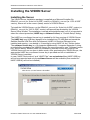
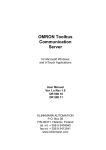
To install the VISION Server, run the DR44010_xxx.msi (for “Suite Link & DDE” version) or
DR44011_xxx.msi (for “OPC & DDE” version) and proceed as directed by the VISION
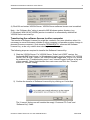
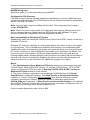
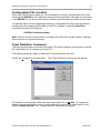
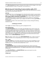
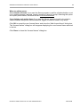
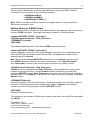
Server Setup Wizard. The installation is simple and straightforward, only it is important to
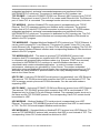
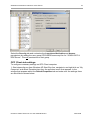
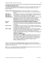
select the correct protection (HASP key or software license) in “Custom Setup” dialog:
The HASP key or software license key is needed for full time running of VISION Server.
The HASP key is an USB key (dongle) to be installed into PC USB port and needs the
SafeNet Sentinel LDK Run-time Environment (HASP HL Runtime Package) to be
installed and running – see details in “Licensing by using HASP HL key” section below.
The software license key is a 16-character alphanumeric “computer-dependent” string,
provided after purchasing the VISION Server (for more information, see “Software license
key” section below. Without HASP key installed or software license key entered, the
VISION Server will run one hour in demo mode. After purchasing the VISION Server, the
appropriate HASP key or software license key is provided and no re-installation of
VISION Server is needed.
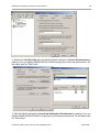
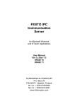
In case “HASP Device driver” and “HASP Files” are not selected then HASP USB key
will not be supported and only the software license will be available (files needed for
HASP USB key will not be installed):
Unitronics Vision Server Ver 3.x User Manual Rev2.6
4401xm26
Klinkmann Automation Unitronics Vision Server
5
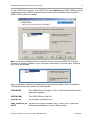
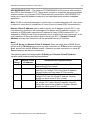
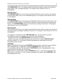
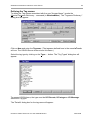
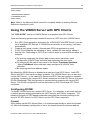
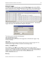
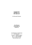
In case “HASP Device driver” and “HASP Files” are selected then HASP USB key will be
supported and both HASP-key and software license will be available (files needed for
HASP USB key will be installed):
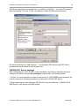
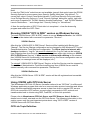
Note: In case the SafeNet Sentinel LDK Run-time Environment (HASP HL Runtime
Package) is already installed on your computer (separately or by some other software)
then it can be disabled:
When installation is finished, the subdirectory specified as a folder where to install the
VISION Server files will contain the following files:
VISION.EXE
The VISION Server Program. This is a Microsoft Windows 32-bit
application program.
VISION.CHM
The VISION Server Help file.
VISION.CFG
An example configuration file.
hasp_windows_44
42.dll
Dynamic Link Library installed only if “HASP Files” is selected
during the installation in “Custom Setup” dialog.
Unitronics Vision Server Ver 3.x User Manual Rev2.6
4401xm26
Klinkmann Automation Unitronics Vision Server
6
haspdinst.exe
Sentinel LDK Run-time Environment Installer (HASP HL
Runtime Package), copied to VISION Server folder only if
“HASP Device driver” is selected during the installation in
“Custom Setup” dialog.
LICENSE.RTF
Klinkmann Automation software license file.
KLSERVER.DLL
Dynamic Link Library necessary for “OPC & DDE” version of
the Server.
WWDLG32.DLL
Dynamic Link Library necessary only for “OPC & DDE” version
Of the Server.
TCPWORK.DLL
Dynamic Link Library necessary for Ethernet communications.
In case the “HASP Device driver” is selected during the installation in “Custom Setup”
dialog, the Sentinel LDK Run-time Environment (HASP HL Runtime Package) is installed
during the VISION Server installation (and will be uninstalled during the VISION Server
uninstallation). The presence of Sentinel LDK Run-time Environment can be checked
after the VISION Server installation by looking-up in Control Panel / Administrative Tools
Services – the Service “Sentinel Local License Manager” must be started.
Notes:
1. The VISION Server “Suite Link & DDE” version is developed with Wonderware I/O
Server Toolkit (ver 7,2,1,6) and needs the Wonderware FS 2000 Common
Components to be installed on computer where the VISION Server is running. If using
Wonderware InTouch 8.0 or newer, install the FS 2000 Common Components before
installing InTouch (see also Wonderware Tech Notes 404 and 313). The Wonderware
FS2000 Common Components are installed automatically when any of Wonderware
product (e.g. InTouch or some Wonderware I/O server) is installed.
2. If VISION Server “Suite Link & DDE” version will run on PC where Wonderware
FS2000 Common Components are not installed then a special I/O Server Infrastructure
installation package can be obtained from Klinkmann Automation (see Installing the
I/O Server Infrastructure section below). This I/O Server Infrastructure installation
package contains the minimum set of software needed to run the VISION Server and
these infrastructure files must be install prior to executing the VISION Server.The I/O
Server Infrastructure does not support using VISION Server as a Windows Service and
remote access to VISION Server (when DDE/SuiteLink Client is not located on same
computer as VISION Server).
To uninstall the VISION Server, start Control Panel, select “Uninstall a program”
(“Add/Remove Programs” on XP/2003) and select the “VISION SuiteLink and DDE
Server” or “VISION OPC and DDE Server” from the list of available software products.
Click on “Uninstall” (“Add/Remove…” on XP/2003) and proceed as directed by the
Uninstall Wizard.
Unitronics Vision Server Ver 3.x User Manual Rev2.6
4401xm26
Klinkmann Automation Unitronics Vision Server
7
Licensing by using HASP HL key
The following should be done to enable the licensing by HASP HL key:
-
-
-
The “HASP Device driver” and “HASP Files” are selected during the VISION
Server installation in “Custom Setup” dialog – that causes correspondingly
haspdinst.exe and hasp_windows_4442.dll files are copied to VISION Server folder
and Sentinel LDK Run-time Environment (HASP HL Runtime Package) is installed
and started, enabling the VISION Server can detect the HASP HL USB dongle;
insert the received HASP key into USB port, and wait until “Installing device driver
software” message disappears and “Device driver software installed successfully”
message appears;
start VISION Server and check - if “Sofware key or HASP HL key not found!”
message does not appear then it means everything is done correctly and VISION
Server runs in full mode with licensing by HASP HL key enabled.
Software license key
VISION Server supports the “computer dependent” software licensing. The following
steps are required to enable it:
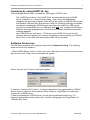
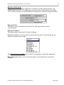
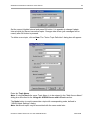
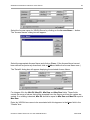
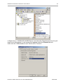
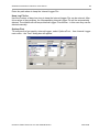
1) Start VISION Server, click on "Help" menu item (also short-cut Alt+H can be used) and
pop-up menu with "Help" menu commands will appear:
Select “License” and “License” dialog will appear:
2) Here the “Customer PC Code” is “computer-dependent” string generated by VISION
Server and it is unique for this computer. Write it down or Copy/Paste to e-mail when
ordering the VISION Server.
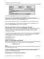
3) After purchasing the VISION Server, you will get the software license key - 16character alphanumeric string. Open the “License” dialog again and Copy/Paste it to
“Software Key” field:
Unitronics Vision Server Ver 3.x User Manual Rev2.6
4401xm26
Klinkmann Automation Unitronics Vision Server
8
4) Click OK and restart VISION Server. VISION Server software license now is enabled.
Note – the “Software Key” string is saved to MS Windows system directory (e.g.
C:\Windows) WIN.INI file [VISION] section to enable it is automatically detected at
VISION Server next start-up.
Transferring the software license to other computer
The transfer of Software License Key might be needed in very rare situations when it is
necessary to move Klinkmann software to other computer (or operation system change is
planned for same computer). Such transfer PERMANENTLY removes the Software
License Key, so be very careful when deciding to use this option.
The following steps are required to transfer the Software License Key:
1) Start the VISION Server. For VISION Server “Suite Link & DDE” version, the
ArchestrA SMC Log Viewer (or Wonderware Logger) must be started. For VISION
Server “OPC & DDE” version, the VISION Internal Logger and “Log to File” should
be enabled (see “Troubleshooting menu” and “Internal Logger”sections at the end
of this manual). Select Help/License from main menu and click the “Transfer”
button on “License” dialog:
2) Confirm the transfer of Software License Key by clicking on Yes button:
The “License” dialog now will contain the empty “Customer PC Code” and
“Software Key” fields:
Unitronics Vision Server Ver 3.x User Manual Rev2.6
4401xm26
Klinkmann Automation Unitronics Vision Server
9
3) Take the screenshot from ArchestrA SMC Logger or VISION Internal Log file
window containing the “Software License Key removal message”, like below:
or take the string with “Software License Key removal message” directly from
ArchestrA SMC Logger or VISION Internal Log file, like following:
Software Key 68f6-785f-4f9d-644a removed. PC Code: 61db-1c76-cdd1-3a91,
Product Code: DR44010 325
4) Provide the obtained “Software License Key removal message” screenshot or
string together with new “Customer PC Code” when applying for new Software
License Key without purchasing the new license (in situations when it is necessary
to move Klinkmann software to other computer or operation system change is
planned).
Note!
Without providing the “Software License Key removal message” screenshot or string, the
new Software License Key will not be assigned.
Unitronics Vision Server Ver 3.x User Manual Rev2.6
4401xm26
Klinkmann Automation Unitronics Vision Server
10
Installing the I/O Server Infrastructure
The I/O Server Infrastructure installation package is supplied as a self-extracting archive
(IOServerInfrastructure.exe) and can be downloaded from Klinkmann’s web site.
To install the I/O Server Infrastructure from the self-extracting archive, run the
IOServerInfrastructure.exe and proceed as directed by the I/O Server Infrastructure
Setup program.
To uninstall the I/O Server Infrastructure, start Control Panel, select “Add/Remove
Programs” and select the “IO Server Infrastructure” from the list of available software
products. Click on “Add/Remove…” and proceed as directed by the UnInstallShield
program.
Note: The I/O Server Infrastructure installation will be rejected if Wonderware FS2000
Common Components are already installed on same computer. The I/O Server
Infrastructure does not support using VISION Server as a Windows Service and remote
access to VISION Server (when DDE/SuiteLink Client is not located on same computer
as VISION Server).
Unitronics Vision Server Ver 3.x User Manual Rev2.6
4401xm26
Klinkmann Automation Unitronics Vision Server
11
Connection Cable
To connect Unitronics PLC to the computer, it is possible to use Unitronics standard cable
or self-made connection cable.
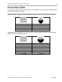
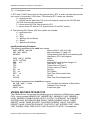
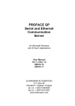
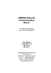
The following wiring diagram can be used to connect computer’s RS-232 serial port and
M200, M90/M91, Vision 120/230/260/280/290/350/570 PLCs communication interface:
PC 9-pin female
4-pin RJ11 male
2 RxD
3 TxD
5 GND
2
3
1
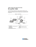
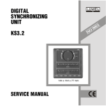
The following wiring diagram can be used to connect computer’s RS-232 serial port and
JAZZ PLC communication interface:
PC 9-pin female
6-pin RJ11 male
2 RxD
3 TxD
4 DTR(out)
5 GND
5 GND
7 RTS(out)
3 TxD(out)
4 RxD(in)
6 PWR(in)
2 GND
5 GND
1 PWR(in)
Unitronics Vision Server Ver 3.x User Manual Rev2.6
4401xm26
Klinkmann Automation Unitronics Vision Server
12
Configuring the VISION Server
After the VISION Server is initially installed, a small amount of configuration is required.
Configuring the Server automatically creates a VISION.CFG file that holds all of the topic
definitions entered, as well as the communication port configurations. This file will
automatically be placed in the same directory in which VISION.EXE is located unless the
path where the configuration file will be placed is specified via the /Configure/Server
Settings... command.
Note!
The VISION Communication Server replaces the former M90 Communication Server. To
use the existing M90 configuration with VISION Communication Server, rename existing
M90.CFG to VISION.CFG and copy it (overwrite default VISION.CFG) to location where
the VISION configuration resides.
Server Settings Command
A number of parameters that control the internal operation of the Server can be set. In
most cases, the default settings for these parameters provide a good performance and do
not require changing. However, they can be changed to fine-tune the Server for a specific
environment.
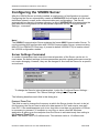
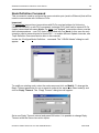
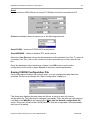
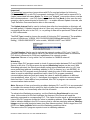
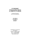
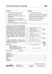
To change the Server's internal parameters, invoke the Configure/Server Settings...
command. The "Server Settings" dialog box will appear:
The following describes each field in this dialog box:
Protocol Timer Tick
This field is used to change the frequency at which the Server checks for work to do (at
this frequency the Server tries to send one data request to PLC and receive one reply
from PLC. If the send/response cycle is too long then more than one activation of Server
is necessary to process it. If computer is very busy or some other MS Windows
application is taking over the computer then the Server is activated rarely than setting in
the Protocol Timer Tick.
Note: The default value is 50 milliseconds. The minimum value is 10 milliseconds.
Unitronics Vision Server Ver 3.x User Manual Rev2.6
4401xm26
Klinkmann Automation Unitronics Vision Server
13
NetDDE being used
Select this option if you are networking using NetDDE.
Configuration File Directory
This field is used to specify the path (disk drive and directory) in which VISION will save
its current configuration file. The VISION Server will use this path to load the configuration
file the next time it is started.
Note: Only the "path" may be modified with this field. The configuration file is always
named VISION.CFG.
Note: There is no limit to the number of configuration files created, although each must
be in a separate directory. When using the VISION Server with InTouch, it is good
practice to place the configuration file in the application directory.
Start automatically as Windows NT Service
Enabling this option will cause the VISION Server “Suite Link & DDE” version to start as a
Windows NT service.
Windows NT offers the capability of running applications even when a user is not logged
on to the system. This is valuable when systems must operate in an unattended mode.
Enabling this option and rebooting the system will cause the Server to run as a Windows
NT service. However, to view configuration information or to reconfigure the Server, the
user must log on to the system. Any Server related problems that may arise such as
missing adapter cards, licensing failures or device drivers not loading will not be visible to
the user until a log on is performed. Disabling this option and rebooting the system will
cause the Server to run as a Windows NT application program once again.
Notes:
1. The Start automatically as Windows NT Service feature can be activated only with
VISION Server “Suite Link & DDE” version. To start the VISION Server “OPC & DDE”
version as Windows NT Service, refer to Running VISION “OPC & DDE” version as
Windows NT Service section of this manual.
2. The Service Startup configuration can be changed by MS Windows NT Control
Panel/Services configuration dialogs. The Allow Service to Interact with Desktop
checkbox in “Service” dialog box must be checked (the “Service” dialog box can be
invoked by pressing the “Startup” button on “Services” dialog box when Service
VISION_IOServer is selected). If Allow Service to Interact with Desktop is not selected
then VISION Server full functionality is not ensured (e.g. the Server configuration can not
be changed, no message boxes will be displayed, etc.).
Once all entries have been made, click on OK.
Unitronics Vision Server Ver 3.x User Manual Rev2.6
4401xm26
Klinkmann Automation Unitronics Vision Server
14
Node Definition Command
This command is used to configure the communication port (serial or Ethernet) that will be
used to communicate with Unitronics PLCs.
Important!
For networked connections (connections with PLCs used as bridges (to Unitronics
CANbus or RS-485) or with PLCs accessed via bridge PLC) there can be several PLCs
(topics) associated with same Node. For direct (not “bridged”) connections there must be
strict correspondence – one PLC (topic) associated with one Node (in this case the only
exception can be several topics for same PLC – to enable different Update Intervals, see
Topic Definition Command section later in this manual).
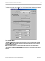
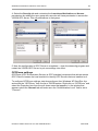
Invoke the /Configure/Node Definition... command. The "VISION Nodes" dialog box will
appear:
To modify an existing node, select the node name and click on Modify. To change the
Reply Timeout parameter for one or several nodes at the same time select node(s) and
click on Reply Timeout. The “Reply Timeout” dialog box will appear:
Set a new Reply Timeout interval and press OK button. It is possible to change Reply
Timeout while the Server has active topics.
Unitronics Vision Server Ver 3.x User Manual Rev2.6
4401xm26
Klinkmann Automation Unitronics Vision Server
15
To define a new node, click on New. The "VISION Node Settings" dialog box will appear:
Enter the Node Name.
The Reply Timeout field is used to enter the amount of time (in milliseconds, seconds,
minutes or hours) the Controller connected to the selected port will be given to reply to
commands from the Server.
Note. The default value of 10 seconds should be sufficient for most configurations.
Three following Types of Communication (Server and PLC connection modes) can be
selected:
Unitronics Vision Server Ver 3.x User Manual Rev2.6
4401xm26
Klinkmann Automation Unitronics Vision Server
16
Ethernet (server mode)
In this mode the Server waits for TCP or UDP connection from remote client (VISION
PLC). The first information message from the client should be the specified ID String.
Once the string is received, the Server starts to poll the PLC.
Local IP Port field is used to enter TCP or UDP port number in which the Server is
waiting (listens) for connection from PLC side. All nodes can use the same port number or
different port numbers for different nodes can be used.
ID String field is used to define the string, which PLC can send as the first data message
to the Server and which the latter uses to identify the PLC connecting. This string can
contain up to 35 ASCII characters. If necessary, ID String can be ended with <CR>
(Carriage Return, 0D in hex) - in this case Server expects to receive all ASCII characters
specified before <CR> and then 0D in hex as a last byte of ID String. Recommended
practice is to include the PLC Unit Number here, for example, if PLC Unit Number is 1
then ID String value can be #01 or #01<CR>.
In case of TCP connection ID String message can be omitted (the field left free) – in this
case Server will accept any connection. If ID strings are not used, different nodes should
use different ports.
Notes:
1) If ID String field is not empty, the communication between VISION Server and PLC will
not start without receiving the ID String.
2) The ID String can be sent from PLC serial port or from GPRS-modem embedded
application (in case GPRS-modem has such a feature).
Protocol combobox is used to select the communication protocol. It is possible to select
one of the following protocols:
TCP PCOM – Unitronics PCOM ASCII serial protocol (encapsulated) over TCP/IP
Ethernet. The TCP messages contain pure serial PCOM commands. The protocol implies
that at PLC side the TCP/serial conversion is performed (e.g. by GPRS-modem
Unitronics Vision Server Ver 3.x User Manual Rev2.6
4401xm26
Klinkmann Automation Unitronics Vision Server
17
embedded application) and serial commands/responses are transferred to/from
UNITRONICS PLC serial port. The protocol is dedicated for PLC+modem use.
TCP PCOM/IP – Unitronics PCOM/IP (PCOM over Ethernet) ASCII protocol over TCP/IP
Ethernet. This protocol is used if Vision PLC is a node inside Ethernet LAN. The Ethernet
port of Vision PLC is connected. The message header structure is proprietary Unitronics.
TCP MODBUS – Modicon Modbus RTU serial protocol (encapsulated) over TCP/IP
Ethernet. The TCP messages contain pure Modbus serial commands. The protocol
implies that at PLC side the TCP/serial conversion is performed (e.g. by GPRS-modem
embedded application) and serial commands/responses are transferred to/from
UNITRONICS PLC serial port. The protocol is dedicated for PLC+modem use. The PLC
OS should support Modbus serial interface and corresponding Modbus FBs should be
added in the PLC program.
TCP MODBUS/IP – Standard Modicon Modbus/IP RTU protocol over TCP/IP Ethernet. It
can be used to access PLC over Ethernet. This protocol is used if Vision PLC is a node
inside Ethernet LAN. Supported only for Vision PLCs with Ethernet enabled. The PLC OS
should support Modbus Ethernet interface and corresponding Modbus IP FBs should are
added in the PLC program
TCP MODBUS/IP+LRC – The same as previous TCP MODBUS/IP protocol with
exception that RTU messages are supplied with LRC checksums. The protocol is meant
to cooperate with programmable wireless modem (e.g. Siemens TC65T/Java terminal)
connected to UNITRONICS PLC serial port in case the Modbus checksum is not
calculated inside modem embedded application - in order to increase modem’s
performance, checksums are calculated by Vision Server. The modem embedded
application removes Modbus/IP protocol header from message before sending it to PLC
and adds the same Modbus/IP protocol header to the reply message before sending it
back to the Vision Server.
UDP PCOM – Unitronics PCOM ASCII serial protocol (encapsulated) over UDP Ethernet.
The same as TCP PCOM protocol with exception that UDP is used instead of TCP. The
UDP messages contain pure serial PCOM commands. Can be used with modems
supporting UDP.
UDP PCOM/IP – Unitronics PCOM/IP (PCOM over Ethernet) protocol over UDP Ethernet.
The same as TCP PCOM/IP protocol with exception that UDP is used instead of TCP.
Supported only for Vision PLCs with Ethernet enabled. The message header structure is
the same as with TCP PCOM/IP protocol. The corresponding Vision PLC socket should
be switched to UDP.
UDP MODBUS – Modicon Modbus RTU serial protocol (encapsulated) over UDP
Ethernet. The same as TCP MODBUS protocol with exception that UDP is used instead
of TCP. The PLC OS should support Modbus serial interface.
UDP MODBUS/IP – Standard Modicon Modbus/IP RTU protocol over UDP Ethernet. The
same as TCP MODBUS/IP protocol with exception that UDP is used instead of TCP. The
corresponding Vision PLC socket should be switched to UDP.
Unitronics Vision Server Ver 3.x User Manual Rev2.6
4401xm26
Klinkmann Automation Unitronics Vision Server
18
UDP MODBUS/IP+LRC – The same as TCP MODBUS/IP+LRC protocol with exception
that UDP is used instead of TCP. The protocol is meant to cooperate with programmable
wireless modem (e.g. Siemens TC65T/Java terminal) connected to UNITRONICS PLC
serial port in case the Modbus checksum is not calculated inside modem embedded
application.
Note: if UDP is used and messages in protocol do not contain transaction ID, that can be
a reason for some kind of mismatches in case of slow or loaded GPRS communication.
Remote Client IP Address field is used to specify the IP address of client (PLC), only
from where the connection will be accepted. Not always this IP address is known – for
example, in GPRS public network the IP address for client (GPRS-modem+PLC) is
assigned by GPRS Access Point dynamically and it is different at each connection, so for
such cases the ID String should be used to identify the PLC. If Remote Client IP
Address is empty then connection will be accepted from any IP address.
Note!
If both ID String and Remote Client IP Address fields are empty then VISION Server
will not wait for ID String and accepts any new connection on IP Port. In this case each
Node should have unique IP Port number, otherwise any new connection on same IP
Port will destroy the previous connection.
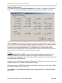
The following table illustrates possible ID String and Remote Client IP Address
variations and recommended implementations:
ID
String
-
+
+
Remote Client
Recommended implementation
IP Address
Point-to-point wired or GPRS connection. Each Node
has unique IP Port number.
+
Wired or GPRS (corporate network) connection where
each PLC (or “bridge” PLC) has a fixed IP address.
Several Nodes can have same IP Port number.
GPRS connection (public network) where each PLC (or
“bridge” PLC) has not a fixed IP address. Several
Nodes can have same IP Port number.
+
GPRS connection (corporate network) where each PLC
(or “bridge” PLC) has a fixed IP address. Using ID
String can improve the reliability of system. Several
Nodes can have same IP Port number.
Unitronics Vision Server Ver 3.x User Manual Rev2.6
4401xm26
Klinkmann Automation Unitronics Vision Server
19
Ethernet (client mode)
This mode can be used when target PLC IP address is known and accessible - the
VISION Server acts as TCP or UDP client. In this case the VISION Server is initiating
TCP or UDP connection to UNITRONICS PLC waiting for connection (acting as server):
Remote IP Port
This field is used to enter the PLC side TCP or UDP port number used for
communication.
Remote IP Address
This field is used to enter the PLC side IP Address.
Protocol combobox is used to select communication protocol. The protocols are the
same as using the server mode:
See Ethernet (server mode) section above for explanation of protocols supported.
Retry Delay (sec) field is used to enter the delay in seconds between connection
attempts.
Unitronics Vision Server Ver 3.x User Manual Rev2.6
4401xm26
Klinkmann Automation Unitronics Vision Server
20
Serial
In this mode the VISION Server is using PC COM port for direct connection to PLC:
Protocol combobox allows to select one of the following protocols:
Serial PCOM – Unitronics PCOM ASCII serial protocol.
Serial MODBUS – Modicon Modbus RTU serial protocol.
Select the Com Port and choose the characteristics of the selected Com Port. To select a
necessary Com Port, click on the combo box button and make your choice from the list
box.
Once the parameter values have been entered, click OK button to process the
configuration for the node or press Cancel to reject the entered parameters.
Saving VISION Configuration File
If the configuration file does not currently exist, or a new configuration path has been
specified, the Server will display the "Save Configuration" dialog box:
This dialog box displays the path where the Server is going to save the current
configuration file. The path may be changed if necessary. Also, the path can optionally be
recorded in the WIN.INI file by selecting the "Make this the default configuration file"
option. Doing so it will allow the VISION Server to find the configuration file automatically
each time it is started.
Unitronics Vision Server Ver 3.x User Manual Rev2.6
4401xm26
Klinkmann Automation Unitronics Vision Server
21
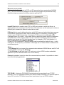
Configuration File Location
When the VISION Server starts up, it first attempts to locate it’s configuration file by first
checking the WIN.INI file for a path that was previously specified. If the path is not present
in the WIN.INI file, the Server will assume that the current working directory is to be used.
To start the Server from an application directory configuration file other than the default
configuration file a special switch (/d:) is used. For example, invoke the Start/Run
command and enter the following:
VISION/d:c:\directoryname
Note: There is no limit to the number of configuration files that may be created, although
each must be in a separate directory.
Topic Definition Command
The user provides each connected Unitronics PLC with an arbitrary name that is used as
the Topic Name for all references to this PLC.
The following steps are taken to define the Topic attached to the PLC:
Invoke the Configure/Topic Definition… The "Topic Definition" dialog box will appear:
To modify an existing topic, select the topic name and click on Modify. To change the
Update Interval parameter for one or some topics at the same time select topic(s) and
click on Update Interval. The “Update Interval” dialog box will appear:
Unitronics Vision Server Ver 3.x User Manual Rev2.6
4401xm26
Klinkmann Automation Unitronics Vision Server
22
Set the correct Update Interval and press OK button. It is possible to change Update
Interval while the Server has active topics. Changes take effect (poll messages will be
resent) after OK button is pressed.
To define a new topic, click on New. The "Vision Topic Definition" dialog box will appear:
Enter the Topic Name.
Note: If using InTouch the same Topic Name is to be entered in the "Add Access Name"
dialog box described in the Using the VISION Server with InTouch section.
The Node button is used to associate a topic with corresponding node, defined in
“VISION Node Settings” dialog.
Note: Additional topics may be associated with the same node later.
Unitronics Vision Server Ver 3.x User Manual Rev2.6
4401xm26
Klinkmann Automation Unitronics Vision Server
23
Important!
For networked connections (connections with PLCs used as bridges (to Unitronics
CANbus or RS-485) or with PLCs accessed via bridge PLC) there can be several PLCs
(topics) associated with same Node. For direct (not “bridged”) connections there must be
strict correspondence – one PLC (topic) associated with one Node (in this case the only
exception can be several topics for same PLC – to enable different Update Intervals, see
Topic Definition Command section later in this manual).
The Update Interval field is used to indicate how often the items/points on this topic will
be read (polled). If Update Interval value is 0 then only write and watchdog (if configured)
commands will be sent to the PLC, i.e. no polling of data will be performed. Default value
is 1000 milliseconds.
The PLC Type is used to choose the model of Unitronics PLC connected. The available
groups of models are “VISION 120/130/230/260/280/290Black&White/530” (default
setting), “VISION 290/350/570” color models, “M90/M91/JAZZ” and “M200”:
The Unit Number field is used to indicate the network number of PLC unit (“Unit ID”)
currently configured. With default value (0) the Server can communicates to Unitronics
PLC directly connected to COM port regardless of its network number.
Important: Beware of using value 0 as unit number in CANBUS network!
Watchdog
In some cases PLC program needs to check if communication between PLC and VISION
Server is still alive. For this purpose the special Watchdog feature can be used. With
Watchdog activated, the Server periodically writes some predefined value (e.g.21) into
some predefined address (watchdog address) in PLC’s memory (e.g. into MI1000). At
same time the PLC program must periodically check the value in this memory address. If
value is equal to watchdog’s predefined value, then PLC’s program considers
communication status as good and resets the value of watchdog address to different
(non-predefined) value, e.g. to 0 – that allows for program to check the communication
state next time. If value differs from predefined, then PLC’s program can consider
communication status as bad.
Note: Because of time synchronizing problems between PLC and PC, it is recommended
to consider the communication status as bad only after few consecutive watchdog value
mismatch cases, not immediately after the first mismatch.
To activate the Watchdog processing - set the Watchdog Send Interval to non-zero
value. Value entered in this field indicates the frequency the Server will send the
watchdog command to corresponding PLC. This value must be equal or bit less as time
interval the PLC program checks the value in watchdog address. Enter Memory Integer
field to indicate address in the PLCs memory that is used as watchdog address. Memory
Integer must be valid item/point name (see Item Names section.) Enter integer from 0 to
65535 into Value to Write field to set the Watchdog predefined value.
The same value PLC program expects to see in watchdog address.
Unitronics Vision Server Ver 3.x User Manual Rev2.6
4401xm26
Klinkmann Automation Unitronics Vision Server
Unitronics Vision Server Ver 3.x User Manual Rev2.6
24
4401xm26
Klinkmann Automation Unitronics Vision Server
25
Capacity of Responses
It is possible to set the Capacity of Responses by clicking on “Capacity of Responses
button…”. The following “Maximum Capacity of Responses” dialog box will appear:
These values should be changed to make the communication optimal or in case of bad
communications. It is possible to determine the maximum of response capacity for poll
requests. Different limits can be specified for response capacity of PLC memory address
areas. The value in the dialog box specifies how many consecutive values can be
received by one poll request message. The VISION Server virtually divides polled
memory area of controller and this value specifies the length of each memory chunk. For
each memory chunk the Server creates one poll message.
Example:
Value 25 for MEMORY INTEGERs means that maximum capacity of response is 25
values of MEMORY INTEGERs. Values from item MI0 to MI24 (including) can be
requested in one message. If the value for item MI25 is requested, the next message will
be generated by VISION Server.
When all entries in “Maximum Capacity of Responses” dialog box have been made, click
on OK to return to the “VISION Topic Definition” dialog.
When all entries in “VISION Topic Definition” dialog box have been made, click on OK to
process the configuration for this topic.
Select Done in "Topic definition" dialog box when configuration for all Topics has been
performed.
Unitronics Vision Server Ver 3.x User Manual Rev2.6
4401xm26
Klinkmann Automation Unitronics Vision Server
26
Item Names
It is possible to communicate with following types of UNITRONICS PLCs:
- VISION 120/130/230/260/280/290Black&WhiteW/530,
- VISION 290Color/350/570/1040/1210,
- M90/M91/JAZZ,
- M200.
VISION 120/130/230/260/280/290BW/530
The VISION Server can access the following types of Unitronics VISION series
“black&white” PLCs memory areas: MEMORY INT, MEMORY BIT, MEMORY FLOAT,
MEMORY LONG, MEMORY DOUBLE WORD, INPUT, OUTPUT, SYSTEM INT,
SYSTEM BIT, SYSTEM LONG, SYSTEM DOUBLE WORD, TIMER CURRENT VALUE,
TIMER PRESET VALUE, TIMER SCAN BIT, COUNTER CURRENT VALUE, COUNTER
PRESET VALUE, COUNTER SCAN BIT, REAL TIME CLOCK, UNIT ID and PLC
STATUS. The supported item/point types are Discrete, Integer, Real and String. For
item/point naming it is recommended to use the consecutive addresses (for example,
MI16, MI17, MI18, etc.) - that can considerably increase the performance of VISION
Server.
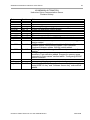
The table below lists the item/point names supported by VISION Server for VISION
120/130/230/260/280/290Black&White/530 PLCs:
Notes:
1. Also lower case letters mi, mb, inp, out, si, sb, etc. can be used as item name first
characters.
2. All addresses are decimal.
3. For Discrete INP and OUT items the last digit (b) represents the bit position inside the
byte. The bit position can be from 0 to 7.
4. For MI and ML string items the length of string p is the number of 16-bit integers (MI) or
32-bit integers (ML) in the string; correspondingly the number of characters in the string is
p * 4 for MI and p * 8 for ML.
5. Inputs (INPnn), Timer Current Values (TCn), Timer Preset Values (TPn), Timer Scan
Bits (TSn), Counter Current Values (CCn), Counter Preset Values (CPn), Counter Scan
Bits (CSn) are Read Only. System Bits (SBn), System Integers (SIn), System Longs
(SLn) and System Doubles (SDn) are Read/Write or Read Only depending on how they
are use in the PLC. Set Key (SK), PLC Status (PS) and Real Time Clock (RTC) items are
Write-Only.
6. CLOCK item value has the following format:
HH:mm:ss ddd DD/MM/YY, where
HH – hour (0…23);
mm – minutes (0…59);
ss – seconds (0…59);
ddd – week day (Mon, Tue, Wed, Thu, Fri, Sat, Sun);
DD – day of month (1…31);
MM – month (1…12);
Unitronics Vision Server Ver 3.x User Manual Rev2.6
4401xm26
Klinkmann Automation Unitronics Vision Server
27
YY – 2 last digits of year.
7. RTC and CLOCK items don’t act like general items. RTC is write-only item that provide
the control of read-write CLOCK item. The following RTC values are valuable:
0 – neutral position;
1 – VISION server reads the PLC clock and extracts value into the CLOCK item
(CLOCK item must be activated);
2 – server writes CLOCK item content to PLC;
3 - server writes PC time to PLC (synchronize PC and PLC clocks);
8. The following PLC Status (PS) item values are valuable:
0 – neutral position,
1 – ‘Run’,
2 – ‘Stop’,
3 – ‘Memory init and Reset’,
4 – ‘Reset’,
5 – ‘Switch to BootStrap‘.
Item/Point Naming Examples
The following examples show valid item names:
MB0 MB109 mb1104
Memory Bits 0, 109 and 1104
MI0 MI9 MI615
Memory Integer 0, 9 and 615
MI10S12
String starting from MI10 and containing 48
characters (12 16-bit integers)
INP0 INP31 INP543
Inputs
OUT0 OUT543
Outputs
SB2 si10
System Bit 2 and System Integer 10
TS2
Scan Bit of Timer 2
TP2
Preset Value of Timer 2
TC5
Current Value of Timer 2
SK sk
Set Key
PS ps
PLC Status
RTC rtc
Real Time Clock control item
ID id
Unit ID
CLOCK
Real Time Clock display item
The following examples show invalid item names:
MI MB inp8,1 out08
Too few digits for Address or Bit position
MI602400
Address is out of range
MN22 m001
Invalid item type
VISION 290/350/570/1040/1210
The VISION Server can access the following types of Unitronics VISION series “color”
PLCs memory areas: MEMORY INT, MEMORY BIT, MEMORY FLOAT, MEMORY
LONG, MEMORY DOUBLE WORD, INPUT, OUTPUT, SYSTEM INT, SYSTEM BIT,
SYSTEM LONG, SYSTEM DOUBLE WORD, TIMER CURRENT VALUE, TIMER
PRESET VALUE, TIMER SCAN BIT, COUNTER CURRENT VALUE, COUNTER
PRESET VALUE, COUNTER SCAN BIT, FAST BITS, FAST INTEGER, FAST LONG,
FAST DOUBLE, REAL TIME CLOCK, UNIT ID and PLC STATUS. The supported
Unitronics Vision Server Ver 3.x User Manual Rev2.6
4401xm26
Klinkmann Automation Unitronics Vision Server
28
item/point types are Discrete, Integer, Real and String. For item/point naming it is
recommended to use the consecutive addresses (for example, MI16, MI17, MI18, etc.) that can considerably increase the performance of VISION Server.
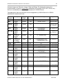
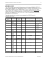
The table below lists the item/point names supported by VISION Server for VISION
290/350/570/1040/1210 PLCs:
Item
name
MBn
MIn
MInSp
MLn
MLnSp
MDn
MFn
INPn
OUTn
SBn
SIn
SLn
SDn
TCn
TPn
TSn
CCn
CPn
Description
Bit
Integer
(16bit)
Integer
(16bit)
string
Integer
(32bit)
Integer
(32bit)
string
Unsigned
Integer
(32bit)
Float point
including
sign(32bit)
Bit
Bit
Bit
Integer
(16bit)
Integer
(32bit)
Unsigned
Integer
(32bit)
Unsigned
Integer
(32bit)
Unsigned
Integer
(32bit)
Bit
Unsigned
Integer
(32bit)
Unsigned
Integer
(32bit)
Tag
Type
Discrete
Integer
Modbus
Value Range
Yes
Yes
0,1
-32768...32767
String
Yes
Integer
Yes
String
Yes
Integer
Yes
0... 4294967295
n = 0 to 255
Real
Yes
-3.402823466 E+38
…3.402823466 E+38
n = 0 to 63
Discrete
Discrete
Discrete
Integer
Yes
Yes
Yes
Yes
0,1
0,1
0,1
-32768...32767
n = 0 to 543
n = 0 to 543
n = 0 to 511
n = 0 to 511
Integer
Yes
n = 0 to 55
Integer
Yes
-2147483648...
2147483647
0... 4294967295
Integer
No
0... 4294967295
n = 0 to 383
Integer
No
0... 4294967295
n = 0 to 383
Discrete
Integer
No
No
0,1
0... 4294967295
n = 0 to 383
n = 0 to 31
Integer
No
0... 4294967295
n = 0 to 31
Unitronics Vision Server Ver 3.x User Manual Rev2.6
Range
n=0 to 8191
n=0 to 4095
n=0 to 8191,
p = 1 to 63
-2147483648...
2147483647
n = 0 to 511
n = 0 to 511,
p = 1 to 31
n = 0 to 63
4401xm26
Klinkmann Automation Unitronics Vision Server
CSn
PS
Bit
Unsigned
Integer
(16bit)
SK
Unsigned
Integer
(16bit)
ID
Unsigned
Integer
(16bit)
RTC
Unsigned
Integer
(16bit)
CLOCK String
XBn
Bit
XIn
Integer
(16bit)
XLn
Integer
(32bit)
XDn
Unsigned
Integer
(32bit)
29
Discrete
Integer
No
No
0,1
1, 2, 3, 4, 5
n = 0 to 31
Integer
No
0…255
Integer
No
0…255
Integer
No
1, 2, 3
String
Discrete
Integer
No
Yes
Yes
0,1
-32768...32767
n=0 to 1023
n = 0 to 511
Integer
Yes
n = 0 to 255
Integer
Yes
-2147483648...
2147483647
0... 4294967295
n = 0 to 63
Notes:
1. Also lower case letters mi, mb, inp, out, si, sb, etc. can be used as item name first
characters.
2. All addresses are decimal.
3. For Discrete INP and OUT items the last digit (b) represents the bit position inside the
byte. The bit position can be from 0 to 7.
4. For MI and ML string items the length of string p is the number of 16-bit integers (MI) or
32-bit integers (ML) in the string; correspondingly the number of characters in the string is
p * 4 for MI and p * 8 for ML.
5. Inputs (INPnn), Timer Current Values (TCn), Timer Preset Values (TPn), Timer Scan
Bits (TSn), Counter Current Values (CCn), Counter Preset Values (CPn), Counter Scan
Bits (CSn) are Read Only. System Bits (SBn), System Integers (SIn), System Longs
(SLn) and System Doubles (SDn) are Read/Write or Read Only depending on how they
are use in the PLC. Set Key (SK), PLC Status (PS) and Real Time Clock (RTC) items are
Write-Only.
6. CLOCK item value has the following format:
HH:mm:ss ddd DD/MM/YY, where
HH – hour (0…23);
mm – minutes (0…59);
ss – seconds (0…59);
ddd – week day (Mon, Tue, Wed, Thu, Fri, Sat, Sun);
DD – day of month (1…31);
MM – month (1…12);
YY – 2 last digits of year.
Unitronics Vision Server Ver 3.x User Manual Rev2.6
4401xm26
Klinkmann Automation Unitronics Vision Server
30
7. RTC and CLOCK items don’t act like general items. RTC is write-only item that provide
the control of read-write CLOCK item. The following RTC values are valuable:
0 – neutral position;
1 – VISION server reads the PLC clock and extracts value into the CLOCK item
(CLOCK item must be activated);
2 – server writes CLOCK item content to PLC;
3 - server writes PC time to PLC (synchronize PC and PLC clocks);
8. The following PLC Status (PS) item values are valuable:
0 – neutral position,
1 – ‘Run’,
2 – ‘Stop’,
3 – ‘Memory init and Reset’,
4 – ‘Reset’,
5 – ‘Switch to BootStrap‘.
Item/Point Naming Examples
The following examples show valid item names:
MB0 MB109 mb1104
Memory Bits 0, 109 and 1104
MI0 MI9 MI615
Memory Integer 0, 9 and 615
ML5S6
String starting from ML5 and containing 48
characters (6 32-bit integers)
INP0 INP31 INP543
Inputs
OUT0 OUT543
Outputs
SB2 si10
System Bit 2 and System Integer 10
TS2
Scan Bit of Timer 2
TP2
Preset Value of Timer 2
TC5
Current Value of Timer 2
SK sk
Set Key
PS ps
PLC Status
RTC rtc
Real Time Clock control item
ID id
Unit ID
CLOCK
Real Time Clock display item
The following examples show invalid item names:
MI MB inp8,1 out08
Too few digits for Address or Bit position
MI602400
Address is out of range
MN22 m001
Invalid item type
Unitronics Vision Server Ver 3.x User Manual Rev2.6
4401xm26
Klinkmann Automation Unitronics Vision Server
31
M90/M91/JAZZ
The VISION Server can access the following types of Unitronics M90/M91/JAZZ PLC
memory areas: MEMORY INT, MEMORY BIT, INPUT, OUTPUT, SYSTEM INT, SYSTEM
BIT, TIMER CURRENT VALUE, TIMER PRESET VALUE, TIMER SCAN BIT, REAL
TIME CLOCK, UNIT ID and PLC STATUS. The supported item/point types are Discrete,
Integer and String. For item/point naming it is recommended to use the consecutive
addresses (for example, MI16, MI17, MI18, etc.) - that can considerably increase the
performance of VISION Server.
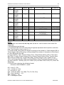
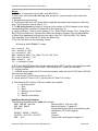
The table below lists the item/point names supported by VISION Server for
M90/M91/JAZZ PLCs:
Item
name
MBn
Min
Modbus
Value Range
Yes
Yes
0,1
-32768...32767
INPnn,b
Bit
Integer
(16bit)
Integer
String
(16bit) string
Bit
Discrete
Yes
0,1
OUTnn,b
Bit
Discrete
Yes
0,1
Sin
Integer
(16bit)
Bit
Unsigned
Integer
(16bit)
Unsigned
Integer
(16bit)
Bit
Unsigned
Integer
(16bit)
Unsigned
Integer
(16bit)
Unsigned
Integer
(16bit)
Unsigned
Integer
(16bit)
String
Integer
Yes
-32768...32767
Discrete
Integer
Yes
No
0,1
0…65535
n = 0 to 255
n = 0 to 63
Integer
No
0…65535
n = 0 to 63
Discrete
Integer
No
No
0,1
1, 2, 3, 4, 5
n = 0 to 63
Integer
No
0…255
Integer
No
0…255
Integer
No
1, 2, 3
String
No
MInSp
SBn
TCn
TPn
TSn
PS
SK
ID
RTC
CLOCK
Description
Tag
Type
Discrete
Integer
Yes
Unitronics Vision Server Ver 3.x User Manual Rev2.6
Range
n = 0 to 255
n = 0 to 255
n = 0 to 255, p
= 1 to 63
n = 00 to 159
b = 0 to 7
n = 00 to 159
b = 0 to 7
n = 0 to 255
4401xm26
Klinkmann Automation Unitronics Vision Server
32
Notes:
1. Modbus is supported only for M91 and JAZZ PLCs.
2. Also lower case letters mi, mb, inp, out, si, sb, etc. can be used as item name first
characters.
3. All addresses are decimal.
4. For Discrete INP and OUT items the last digit (b) represents the bit position inside the
byte. The bit position can be from 0 to 7.
5. For MI string items the length of string p is the number of 16-bit integers in the string;
correspondingly the number of characters in the string is p * 4.
6. Inputs (INPnn,b), Timer Current Values (TCn), Timer Preset Values (TPn), Timer Scan
Bits (TSn) are Read Only. System Bits (SBn) and System Integers (SIn) are Read/Write
or Read Only depending on how they are used in the PLC. Set Key (SK), PLC Status
(PS) and Real Time Clock (RTC) items are Write-Only.
7.The CLOCK item has the following format:
HH:mm:ss ddd DD/MM/YY, where
HH – hours (0…23);
mm – minutes (0…59);
ss – seconds (0…59);
ddd – week day (Mon, Tue, Wed, Thu, Fri, Sat, Sun);
DD – day of month (1…31);
MM – month (1…12);
YY – 2 last digits of year.
8. RTC and CLOCK items don’t act like general items. RTC is write-only item that provide
the control of Read/Write CLOCK item. The following RTC values are valuable:
0 – neutral position;
1 – VISION server reads the PLC clock and extracts value into the CLOCK item (CLOCK
item must be activated);
2 – server writes CLOCK item content to PLC;
3 - server writes PC time to PLC (synchronize PC and PLC clocks);
9. The following PLC Status (PS) item values are valuable:
0 – neutral position,
1 – ‘Run’,
2 – ‘Stop’,
3 – ‘Memory init and Reset’,
4 – ‘Reset’,
5 – ‘Switch to BootStrap’.
Item/Point Naming Examples
The following examples show valid item names:
MB0 MB109 mb1104
Memory Bits 0, 109 and 1104
MI0 MI9 MI615
Memory Integer 0, 9 and 615
MI10S12
String starting from MI10 and containing 48
characters (12 16-bit integers)
INP00,0 INP03,1 INP21,7
Inputs
OUT00,0 OUT10,3 OUT63,7
Outputs
SB2 si10
System Bit 2 and System Integer 10
Unitronics Vision Server Ver 3.x User Manual Rev2.6
4401xm26
Klinkmann Automation Unitronics Vision Server
TS2
TP2
TC5
SK sk
PS ps
RTC rtc
ID id
33
Scan Bit of Timer 2
Preset Value of Timer 2
Current Value of Timer 2
Set Key
PLC Status
Real Time Clock
Unit ID
The following examples show invalid item names:
MI MB inp8,1 out08
Too few digits for Address or Bit position
MI1116 INP233,0 OUT00,9
Bit position is out of range
MI602400
Address is out of range
MN22 m001
Invalid item type
M200
The VISION Server can access the following types of Unitronics M200 PLC memory
areas: MEMORY INT, MEMORY BIT, INPUT, OUTPUT, SYSTEM BIT and SYSTEM INT.
The supported item/point types are Discrete and Integer. For item/point naming it is
recommended to use the consecutive addresses (for example, MI16, MI17, MI18, etc.) that can considerably increase the performance of VISION Server.
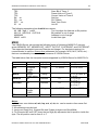
The table below lists the item/point names supported by VISION Server for M200 PLCs:
Item name
MBn
Min
Tag Type
Discrete
Integer
INPnn,b
Description
Bit
Unsigned
integer
(16bit)
Integer
(16bit) string
Bit
Discrete
0,1
OUTnn,b
Bit
Discrete
0,1
Sin
Unsigned
integer
(16bit)
Bit
Integer
0...65535
n = 0 to 65535
Discrete
0,1
n = 0 to 65535
MInSp
SBn
Value Range
0,1
0...65535
String
Range
n = 0 to 1023
n = 0 to 1023
n = 0 to 1023, p =
1 to 63
n = 0 to 63
b = 0 to 7
n = 0 to 63
b = 0 to 7
Notes:
1. Also lower case letters mi, mb, inp, out, si, sb, etc. can be used as item name first
characters.
2. All addresses are decimal.
3. Inputs are Read Only. System Bits and System Integers are Read/Write.
4. For Discrete INP and OUT items the last digit (b) represents the bit position inside the
byte. The bit position can be from 0 to 7.
Unitronics Vision Server Ver 3.x User Manual Rev2.6
4401xm26
Klinkmann Automation Unitronics Vision Server
34
5. For MI string items the length of string p is the number of 16-bit integers in the string;
correspondingly the number of characters in the string is p * 4.
Monitoring and Controlling Communication with a PLC
For each topic, there are following additional items offered by VISION Server to monitor
and control the communication with PLC.
STATUS
For each topic, there is a built-in discrete item that indicates the state of communication
with PLC. The discrete item (STATUS) is set to 0 when communication fails and set to 1
when communication is successful. The STATUS value is set to 0 after 3 consecutive
unsuccessful retries to communicate with this PLC.
From InTouch the state of communication may be read by defining an I/O Discrete
tagname and associating it with the topic configured for the PLC and using STATUS as
the item name.
From Excel, the status of the communication may be read by entering the following
formula in a cell:
=VISION|topic!STATUS
where topic is the name of topic (e.g. plc01) configured for PLC.
UPDATEINTERVAL
The UPDATEINTERVAL item is an Integer type Read/Write item used to access the
currently set Update Interval (see Topic Definition Command section). It indicates the
current requested update interval (in milliseconds). The value of this item can be read
through DDE, Suite Link or OPC. Client can poke new values to this item. The range of
valid values is from 10 to 2147483647 milliseconds. The value of zero indicates that no
items on this topic are updated. The write commands are still executed (new values
written to PLC) if UPDATEINTERVAL value is 0.
Note: By poking a value of zero to the UPDATEINTERVAL item, a client can stop all
update activities on the corresponding topic without having to deactivate the items.
POLL_NOW
The POLL_NOW item is an Integer type Write Only item used for immediate one time
polling of all active items; this one time polling is performed when POLL_NOW value
switches from 0 to 1; no effect when switches from 1 to 0.
MAXINTERVAL
The MAXINTERVAL item is an Integer type Read Only item used to access the
measured maximum update interval (in milliseconds) of all items for the corresponding
topic for the last completed poll cycle. The range of valid values is from 0 to 2147483647
milliseconds.
The UPDATEINTERVAL and MAXINTERVAL items can be used to tune the
performance of communication.
ITEMCOUNT
Unitronics Vision Server Ver 3.x User Manual Rev2.6
4401xm26
Klinkmann Automation Unitronics Vision Server
35
The ITEMCOUNT item is an Integer type Read Only item used to access the number of
active items in the corresponding topic. The range of valid values is from 0 to
2147483647.
ERRORCOUNT
The ERRORCOUNT item is an Integer type Read Only item used to access the number
of active items with errors in the corresponding topic. The range of valid values is from 0
to 2147483647.
ERRORITEMS
The ERRORITEMS item is an Integer type Read/Write Only (unique for each topic) used
to access the total number of items with invalid item names (these items are rejected by
Server). The ERRORITEMS value can be reseted by writing 0 to this item. The range of
valid values is from 0 to 2147483647.
WRITECOUNT
The WRITECOUNT item is an Integer type Read Only item used to access the number of
write commands (messages) waiting for execution. The range of valid values is from 0 to
2147483647.
For example, in following way the WRITECOUNT item can be used to avoid the
increasing of memory occupied by not executed write commands:
- activate the hot link with WRITECOUNT item and start to monitor it;
- activate new write command (by poking new value) only if value of WRITECOUNT
becomes equal to 0, e.g. all previous write commands are executed and memory
occupied by them is freed.
SUSPEND
Special Read/Write Discrete Item SUSPEND may be used to control the communication
with a separate topic. If application changes SUSPEND value from 0 to 1 then
communication with topic is suspended. If SUSPEND value is changed back to 0 then
communication with this topic is resumed.
Note: If topic is suspended by setting SUSPEND value to 1, then Server rejects all new
write values to this topic, i.e. no new write messages are created after SUSPEND value
has changed from 0 to 1.
Unitronics Vision Server Ver 3.x User Manual Rev2.6
4401xm26
Klinkmann Automation Unitronics Vision Server
36
Using the VISION Server with Suite Link and DDE
Clients
The “Suite Link & DDE” version of VISION Server is accessible from Suite Link clients
(e.g. InTouch) and DDE clients (e.g. Excel). The “OPC & DDE” version of VISION Server
is accessible from DDE clients.
Using the VISION Server with InTouch
To access to operands on Unitronics PLCs (M200, M90, M91, JAZZ, VISION
120/230/260/280/290) from InTouch, the Access Names and Tag names should be
defined in WindowMaker.
Defining the Access Names
InTouch uses Access Names to reference real-time I/O data. Each Access Name
equates to an I/O address, which can contain a Node, Application, and Topic. In a
distributed application, I/O references can be set up as global addresses to a network I/O
Server or local addresses to a local I/O Server.
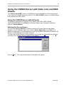
To define the Access Names in WindowMaker node invoke the /Special/Access Names...
command. The "Access Names" dialog box will appear:
Click on Add…. The "Add Access Name" Dialog Box will appear:
Unitronics Vision Server Ver 3.x User Manual Rev2.6
4401xm26
Klinkmann Automation Unitronics Vision Server
37
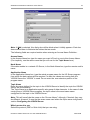
Note: If Add is selected, this dialog box will be blank when it initially appears. Data has
been entered here to illustrate the entries that are made.
The following fields are required entries when entering an Access Name Definition:
Access Name
In the Access Name box type the name you want InTouch to use to this Access Name.
(For simplicity, use the same name that you will use for the Topic Name here.)
Node Name
If the data resides in a network I/O Server, in the Node Name box, type the remote node's
name.
Application Name
In the Application Name box, type the actual program name for the I/O Server program
from which the data values will be acquired. In case the values are coming from the
VISION Server the “VISION” is used. Do not enter the .exe extension portion of the
program name.
Topic Name
Enter the name defined for the topic in the VISION Server to identify the topic the VISION
Server will be accessing.
The Topic Name is an application-specific sub-group of data elements. In the case of data
coming from a VISION Server program, the topic name is the exact same name
configured for the topic in the VISION Server.
Note: This will usually be the same as the "Access Name", although, if desired, they may
be different. However, it must be the same name used when the topics were configured in
section Configuring the VISION Server.
Which protocol to use
Select the protocol (DDE or Suite Link) that you are using.
Unitronics Vision Server Ver 3.x User Manual Rev2.6
4401xm26
Klinkmann Automation Unitronics Vision Server
38
When to advise server
Select Advise all items if you want the Server program to poll for all data whether or not
it is in visible windows, alarmed, logged, trended or used in a script. Selecting this option
will impact performance, therefore its use is not recommended.
Select Advise only active items if you want the Server program to poll only points in
visible windows and points that are alarmed, logged, trended or used in any script.
Click OK to accept the new Access Name and close the “Add Access Name” dialog box.
The “Access Names” dialog box will reappear displaying the new Access Name selected
in the list.
Click Close to close the “Access Names” dialog box.
Unitronics Vision Server Ver 3.x User Manual Rev2.6
4401xm26
Klinkmann Automation Unitronics Vision Server
39
Defining the Tag names
To define the Tag names associated with the new "Access Name", invoke the
/Special/Tagname Dictionary... command (in WindowMaker). The "Tagname Dictionary "
dialog box will appear:
Click on New and enter the Tagname. (The tagname defined here is the name InTouch
will use. The VISION Server does not see this name.)
Select the tag type by clicking on the Type:… button. The "Tag Types" dialog box will
appear:
To access VISION items, the type must be I/O Discrete, I/O Integer or I/O Message.
Select the Tag type.
The "Details" dialog box for the tag name will appear:
Unitronics Vision Server Ver 3.x User Manual Rev2.6
4401xm26
Klinkmann Automation Unitronics Vision Server
40
Select the Access name for VISION Server by clicking on the Access Name:… button.
The "Access Names" dialog box will appear:
Select the appropriate Access Name and click on Close. (If the Access Name has not
been defined as previously described, click on Add and define the Access Name now.)
The "Details" dialog box will appear displaying the selected Access Name:
For integers fill in the Min EU, Max EU, Min Raw and Max Raw fields. These fields
control the range of values that will be accepted from the Server and how the values are
scaled. If no scaling is desired, Min EU should be equal to Min Raw and Max EU equal to
Max Raw.
Enter the VISION item name to be associated with this tagname in the Item: field in the
"Details" box:
Unitronics Vision Server Ver 3.x User Manual Rev2.6
4401xm26
Klinkmann Automation Unitronics Vision Server
41
(Refer to the Item Names section below for complete details.)
Where applicable, the Use Tagname as Item Name option may be selected to
automatically enter the tag name in this field. Note: The tag name can only be used if it
follows the conventions listed in the Item Names section.
Once all entries have been made, click on the Save button (in the top dialog box) to
accept the new tag name. To define additional tagnames click on the New button. To
return to the WindowMaker main screen, select Close.
Monitoring the Status of Communication with InTouch
InTouch supports built-in topic names called DDEStatus and IOStatus that are used to
monitor the status of communications between the Server and InTouch. For more
information on the built-in topic names DDEStatus and IOStatus, see your online
“InTouch User’s Guide”.
The status of communication between the Server and InTouch can be read into Excel by
entering the following DDE reference formula in a cell on a spreadsheet (in following
examples unit1 is the Topic Name configured for VISION Server):
=view|DDEStatus!unit1
or
=view|IOStatus!unit1
Notes on Using Microsoft Excel
Data from the VISION topic (Unitronics PLC) may be accessed from Excel spreadsheets.
To do so, enter a formula like the following into a cell on the spreadsheet.
= VISION|topic!item
Note!
Sometimes, Excel requires the topic and/or item/points to be surrounded by apostrophes
if it is required by Excel syntax.
In the formula, topic must be replaced with one of the valid topic names defined during
the Server configuration process. Replace item with one of the valid item names
described in the Item Names section.
Reading Values into Excel Spreadsheets
Unitronics Vision Server Ver 3.x User Manual Rev2.6
4401xm26
Klinkmann Automation Unitronics Vision Server
42
Values may be read directly into Excel spreadsheets by entering a DDE formatted
formula into a cell, as shown in the following examples:
= VISION|unit1!MI16
= VISION|rack2!MB10
= VISION|'tank-2'!'INP01,3'
Note: Refer to the Microsoft Excel manual for complete details on entering Remote
Reference formulas for cells.
Writing Values to VISION Points
Values may be written to the Server from Microsoft Excel by creating an Excel macro that
uses the POKE command. The proper command is entered in Excel as follows:
channel=INITIATE("VISION","topicname")
=POKE(channel,"itemname", Data_Reference)
=TERMINATE (channel)
=RETURN()
The following describes each of the above POKE macro statements:
channel=INITIATE("VISION","topicname")
Opens a channel to a specific topic name (defined in the Server) in an application with
name VISION (the executable name less the .EXE) and assigns the number of that
opened channel to channel.
Note: By using the channel=INITIATE statement the word channel must be used in
the =POKE statement instead of the actual cell reference. The "applicationname"
and "topicname" portions of the formula must be enclosed in quotation marks.
=POKE(channel,"itemname", Data_Reference)
POKEs the value contained in the Data_Reference to the specified item name (actual
location in the Unitronics PLC) via the channel number returned by the previously
executed INITIATE function. Data_Reference is the row/column ID of the cell containing
the data value. For "itemname", use some of the valid item names described in the Item
Names section.
=TERMINATE(channel)
Closes the channel at the end of the macro. Some applications have a limited number of
channels. Therefore they should be closed when finished. Channel is the channel
number returned by the previously executed INITIATE function.
=RETURN()
Marks the end of the macro.
The following is an example of Excel macro used to poke value from cell B2 to topic unit1
item MI100:
PokeMacro -Ctrl a
=INITIATE("VISION","unit1")
=POKE(A2,"MI100",B2)
=ON.TIME(NOW()+0.01,"TerminateDDEChannel")
Unitronics Vision Server Ver 3.x User Manual Rev2.6
4401xm26
Klinkmann Automation Unitronics Vision Server
43
=RETURN()
TerminateDDEChannel
=TERMINATE(A2)
=RETURN()
Note: Refer to the Microsoft Excel manual for complete details on entering Remote
Reference formulas for cells.
Using the VISION Server with OPC Clients
The “OPC & DDE” version of VISION Server is accessible from OPC Clients.
There are following general steps needed to access an OPC item from VISION Server:
1.
2.
3.
4.
Run OPC Client application and select the “VISION OPC and DDE Server” from the
list of available OPC Servers. If VISION Server currently is not running, it will start
automatically.
Create a new group (or topic if Wonderware OPCLink application is used).
If OPC Client supports the validating of items, validate the item before adding it.
Add the item. Depending on OPC Client it can be done in several different ways, for
example:
a) By entering separately the access path to topic name (valid topic name
configured in VISION Topic definition) and separately the item name.
b) By entering the full path to item name in the format TopicName.ItemName
where TopicName is the valid topic name configured in VISION Topic
definition.
c) By browsing the server address space.
By default the VISION Server is installed and used as a local OPC Server - both OPC
Server and OPC Client reside on same computer. The VISION Server can run also as a
remote OPC Server – in this case OPC Server and OPC Client are located on separate
computers. Accessing the remote OPC Server is same as for local OPC Server, but some
DCOM (Distributed COM) configuration is required before accessing the remote OPC
Server. The DCOM configuration must be done both on OPC Server and OPC Client
computers.
Configuring DCOM
To access VISION Server as a remote OPC Server, it is necessary to do some changes
in default security settings selected for the OPC Server’s and Client’s computers. The
following Windows XP SP2 based explanation describes the necessary settings to be
done for XP SP2 firewall, for OPC Server and for OPC Client computers.
Firewall
When setting up the OPC Server/Client, it is recommended initially to switch the firewall
off. After the necessary configuration is done, the firewall should be restarted and the
Unitronics Vision Server Ver 3.x User Manual Rev2.6
4401xm26
Klinkmann Automation Unitronics Vision Server
44
DCOM port added to the exception list – by selecting ”Add Port...” in firewall ”Exceptions”
pane and adding TCP port 135 as it is needed to initiate DCOM communications:
As well by selecting the ”Add Program...”, all necessary OPC Server and OPC Client
programs should be added to the exception list.
VISION OPC Server settings
After VISION Server “OPC & DDE” version installation, the System Administrator must
configure DCOM by using the dcomcnfg.exe system utility, the following steps:
1. At first, it is recommended to create a local group (i.e. OPCUSERS) that contains a list
of all the users who will have permission to access the VISION OPC server.
2. Start dcomcnfg.exe from Windows XP Start-Run line and select the “VISION OPC &
DDE Server” from the list of DCOM entries:
Unitronics Vision Server Ver 3.x User Manual Rev2.6
4401xm26
Klinkmann Automation Unitronics Vision Server
45
3. Right click on “VISION OPC & DDE Server” and select the Poperties item from the pull
down menu that appears. In the window that appears select the General tab and
make sure the ”Authentication Level” field is set to ”Connect”:
Unitronics Vision Server Ver 3.x User Manual Rev2.6
4401xm26
Klinkmann Automation Unitronics Vision Server
46
4. Select the Security tab and customize the Launch and Activation and Access
permissions by adding the user group with user who will have permission to access the
VISION OPC server. Give all permissions to that group:
5. Now the configuration of OPC Server is completed – close the dcomcnfg program and
restart the VISION OPC Server to put new settings into effect.
OPCEnum settings
OPCEnum (OPC Enumeration Service) is OPC standard component that allows remote
OPC Client to browse the local machine to identify OPC Servers that are installed on it.
To configure OPCEnum settings, start dcomcnfg.exe from Windows XP Start-Run line
and select the “OPCEnum” from the list of DCOM entries. Right click on “OPCEnum” and
select the Poperties item from the pull down menu that appears. In the window that
appears select the General tab and make sure the ”Authentication Level” field is set to
”Connect”:
Unitronics Vision Server Ver 3.x User Manual Rev2.6
4401xm26
Klinkmann Automation Unitronics Vision Server
47
Select the Security tab and customize the Launch and Activation and Access
permissions by adding the user group OPCUSERS same way like for “VISION OPC &
DDE Server”. Give all permissions to that group.
OPC Client side settings
To configure necessary settings on OPC Client computer:
1. Start dcomcnfg.exe from Windows XP Start-Run line, navigate to and right click on “My
Computer” and select Poperties item from the pull down menu that appears. In the
window that appears select the Default Properties tab and make sure the settings there
are filled like as shown below:
Unitronics Vision Server Ver 3.x User Manual Rev2.6
4401xm26
Klinkmann Automation Unitronics Vision Server
48
2. Select the Com Security tab and edit the Default settings for Access Permissions by
adding (if not yet added) ANONYMOUS LOGON and giving it all access permissions. Do
the same also for ”Edit Limits”:
3. Edit the Default settings for Launch and Activation Permissions by adding (if not yet
added) ANONYMOUS LOGON and giving it all all access permissions. Do the same also
for ”Edit Limits”.
Unitronics Vision Server Ver 3.x User Manual Rev2.6
4401xm26
Klinkmann Automation Unitronics Vision Server
49
Note!
In case the ”Edit Limits” selections are not available (grayed) that would mean the DCOM
Security Options for some reason have Security Setting other than ”Not defined”. To
correct that: select Control Panel/ Administrative Tools/Local Security Policy and select
Local Policies/Security Options in ”Local ”Security Settings” dialog box; select, right click
and invoke Properties for ”DCOM: Machine Access Restrictions... ” and ”DCOM: Machine
Launch Restrictions... ” and change their ”Security Setting” to ”Not defined”.
4. Now the configuration of OPC Client side is is completed – close the dcomcnfg
program and restart the OPC Client.
Running VISION “OPC & DDE” version as Windows Service
To install VISION Server “OPC & DDE” version to run as Windows Service, the VISION
Server must be started with command line parameter "/Service":
VISION /Service
After this the “VISION OPC & DDE Server” Service will be installed with Startup type
“Manual”. The Service Startup configuration can be changed by MS Windows XP Control
Panel/Administrative Tools/Services configuration. The Allow service to interact with
desktop checkbox in “Log On” tab must be checked (the “Log On” tab can be invoked
from Poperties item from the pull down menu that appears when right clicking on VISION
OPC & DDE Server Service). If Allow service to interact with desktop is not selected
then VISION Server full functionality is not ensured (e.g. the Server configuration can not
be changed, no message boxes will be displayed, etc.).
To uninstall “VISION OPC & DDE Server” Service, at first the Service must be stopped by
Control Panel/ Administrative Tools/Services/Stop and then VISION Server must be
started manually with command line parameter "/DelService":
VISION /DelService
After this the VISION Server “OPC & DDE” version will be still registered and accessible
to OPC Clients.
Using VISION with OPCLink Server
The Wonderware OPCLink I/O Server (hereafter referred to as “OPCLink”) is a Microsoft
Windows application program that acts as a communication protocol converter and allows
other Windows application programs access to data from local or remote OPC servers.
OPCLink connects to OPC servers, converts client commands to OPC protocol and
transfers data back to clients using DDE, FastDDE, or Suite Link protocols.
Please refer to Wonderware OPCLink Server and OPC Browser User’s Guide for
details how to install, start and use the OPCLink Server. The following information in this
section covers only the most important points about using “OPC & DDE” version of
VISION Server with OPCLink Server.
OPCLink Topic Definition
Unitronics Vision Server Ver 3.x User Manual Rev2.6
4401xm26
Klinkmann Automation Unitronics Vision Server
50
The Topic Definition option from OPC Link Configure menu is used to create, modify, or
delete OPCLink topic definitions. If OPC Link will communicate with VISION Server then
there must exist one or more topics defined for VISION Server. There are following
important fields on the “OPCLink Topic Definition” dialog box:
Topic Name
Enter a unique name (e.g. UNIT1) for the PLC in this field. If using InTouch then same
Topic Name is to be entered in the "Add Access Name" dialog box when defining the
Access Names for OPCLink Server in InTouch WindowMaker.
OPC Server Name
Select the name of the OPC server (VISION.OPC_Server) that will be used by this topic.
The list box shows the registered OPC servers in the system.
OPC Path
Enter the name of the OPC path (e.g. UNIT1.) used by this topic. This OPC path is the
first part of a full OPC item name string common to all items that will be used in this topic.
The available OPC paths for VISION Server can be obtained by clicking on “Browse”
button (this allows to view the VISION Server’s exposed address space).
Update Interval
Enter the frequency (in milliseconds) that the server will acquire data for the items/points
associated with this topic. If 0 (zero) is entered here, OPCLink will not gather data from
VISION Server.
Browse
Clicking on this button initiates the browsing through exposed address space of VISION
Server. The starting addresses of each available data area and names of pre-defined
(additional) items will appear on “Browse OPC items:” window in alphabetical order.
Unitronics Vision Server Ver 3.x User Manual Rev2.6
4401xm26
Klinkmann Automation Unitronics Vision Server
51
Accessing VISION Items via the OPCLink Server
The communication protocol addresses an element of data in a conversation that uses a
three-part naming convention that includes the application name, topic name and item
name. The following briefly describes each portion of this naming convention:
application name
The name of the Windows program (server) that will be accessing the data element. In
the case of data coming from or going to VISION Server “OPC & DDE” version, the
application portion of the address is OPCLINK.
topic name
Meaningful names are configured to identify specific devices (PLCs). These names are
then used as the topic name in all conversations to that device (PLC). This must be same
name as Topic Name entered in the “OPCLink Topic Definition” dialog box, for example,
UNIT1.
Note! You can define multiple topic names for the same PLC to poll different points at
different rates.
item name
A specific data element within the specified topic. The OPCLink Server item syntax
follows the following rules. The item names must start with:
d – discrete value
i – integer value
m – message (string)
The item name added to the OPC path of the topic (without the heading type letter) must
give a fully qualified OPC item name for the VISION Server. Some examples of possible
item names acceptable by OPCLink Server/ VISION Server connection:
iMI0 MEMORY INTEGER, address 0
dMB28 discrete MEMORY BIT, address 28
Unitronics Vision Server Ver 3.x User Manual Rev2.6
4401xm26
Klinkmann Automation Unitronics Vision Server
52
Troubleshooting
WIN.INI entries
The first time you run the VISION Server configuration, most of the items in the following
list will automatically appear in the WIN.INI file, located in the MS Windows system
directory (e.g. C:\WINNT). It is an ASCII file and can be altered manually if you wish with
any text editor, e.g., MS Windows Notepad (do not use a program that formats text, such
as MS Word or Write unless the file is saved as a DOS text). The following is a typical
entry for the VISION Server:
[VISION]
ProtocolTimer=10
ConfigurationFile=C:\VISION\
WinIconic=0
WinFullScreen=0
WinTop=110
WinLeft=0
WinWidth=200
WinHeight=170
DumpScreen=1
The following additional entries can be used:
SlowPollRetries and SlowPollInterval
The SlowPollRetries entry is used to enter the number of consecutive error retries for
one topic. If after SlowPollRetries there is still no successful response from unit
(Unitronics PLC), then this topic is changed to slow poll mode. The WIN.INI file
SlowPollInterval entry is used to enter the slow poll mode update interval (in seconds).
Entering into slow poll mode is reported to WWLogger and (or) to VISION Internal Logger
by following string:
"Node:<NODENAME> Topic:<TOPICNAME>. Set slow poll mode - poll after each
%ld secs. Stop error logging to topic."
Leaving the slow poll mode is reported to WWLogger and (or) to VISION Internal Logger
by following string:
"Node:<NODENAME> Topic:<TOPICNAME>. Return to normal communication to
topic. Error logging reestablished"
The default values (they are used if WIN.INI file does not contain these entries) are
SlowPollRetries equal to 5 and SlowPollInterval equal to 60 seconds.
MultiWrite
If MultiWrite=1 entry is added to WIN.INI file [VISION] section then write commands are
processed in the following way: if server receives some new value to be written to unit
and other writing command to same UNIT address is still pending (waiting for execution)
Unitronics Vision Server Ver 3.x User Manual Rev2.6
4401xm26
Klinkmann Automation Unitronics Vision Server
53
then no new write command is created - the value in existing write command is replaced
by new one. As default (no MultiWrite entry or MultiWrite=0) all write values are
delivered to UNIT, i.e. always new write command is created.
If MultiWrite=2 then Server tries to include the new write value into the some of
previously created messages ignoring the sequence of data changing in the client
application. Server can include into one message only the consecutive item values.
Example: value of MI100 in message with values of items MI99 or MI101.
Important! If MultiWrite=2 then maximum writing speed is achieved, but this option is
not recommended if data changing sequence is important for PLC program!
WriteCapacity
The WriteCapacity entry can be used to specify how many values can be sent (written)
by one write message. The WriteCapacity value becomes effective only starting with
second pending write message, i.e. the first pending write message always will contain
one value. The WriteCapacity entry is relevant only if parameter MultiWrite=2. The
WriteCapacity default value is 1.
MessageRetries
The MessageRetries= entry can be used to specify how many times the VISION server
will try to send any command to PLC. After MessageRetries expires the next command
will be tried. As default (no MessageRetries entry or MessageRetries=2) the
MessageRetries equal to 2 will be used. Note - the topic STATUS item value will change
to 0 when MessageRetries expires.
WriteRetries
The WriteRetries= entry can be used only for write commands to specify how many
times write command will be tried to send. The WriteRetries entry is used together with
MessageRetries in the following way: if after WriteRetries * MessageRetries there is
still no response from PLC then this write command is removed from list of pending write
commands and will be no more executed. As default (no WriteRetries entry or
WriteRetries=3 the WriteRetries equal to 3 will be used. So, if default settings
(MessageRetries=2 and WriteRetries=3) are used, the write command will be deleted
after 6 unsuccessful retries.
Examples:
- by settings MessageRetries=2 and WriteRetries=1 the VISION server will delete write
command after 2 unsuccessful retries;
- by settings MessageRetries=1 and WriteRetries=1 the VISION server will delete write
command immediately after first unsuccessful retry.
FirstPollDelay
The FirstPollDelay= entry can be used to specify how long is pause (delay) between
connection establishing and first poll request issue. As default (no FirstPollDelay entry or
FirstPollDelay=0) the FirstPollDelay equal to 0 will be used.
FirstWDDelay
The FirstWDDelay = entry can be used to specify how long is pause (delay) between
connection establishing and first watchdog write message issue. As default (no
FirstWDDelay entry or FirstWDDelay=0) the FirstWDDelay equal to 0 will be used.
Unitronics Vision Server Ver 3.x User Manual Rev2.6
4401xm26
Klinkmann Automation Unitronics Vision Server
54
Troubleshooting menu
The following debugging choices are appended to the Server’s System Menu (the menu
that appears when you click on the Server icon in the upper left hand corner of the
Server's window):
Suspend Protocol/Resume Protocol - these choices permit you to turn protocol
processing on and off, what means that you can suspend access to
PLC(s).
Show Send
- if checked then all outgoing user data logged in hexadecimal format.
Show Receive
- if checked then all incoming user data logged in hexadecimal format.
Show Errors
- if checked then all information about errors is logged.
Show Bad Writes - if checked then Server displays information about all situations when
data write commands are not executed successfully and after
WriteRetries retries the write is rejected and write message is
deleted from list of active (pending) write messages. This option (if
checked) is effective even if other error logging is stopped.
Verbose
- if checked then additional debugging information is displayed.
Dump
- all information about ports, topics, messages and data items logged.
This can be use to find out how many messages are actually sent to
the PLC(s).
Dump Screen
- if checked then information about active messages are displayed on
the VISION main window. This also can be used to find out how many
messages are actually sent to the PLC(s).
Show Logger
- if checked then VISION Internal Logger is activated and all debug
information is going to VISION Internal Logger (for VISION “Suite Link
& DDE” version the log information will go both to Wonderware
Logger and VISION Internal Logger). The VISION Internal Logger file
is named in the format:
VISION_YYYYMMDD.LOGn
where YYYY is a year, MM is a month, DD is a day and n is a order
number of consecutive VISION Internal Logger file, starting from 1
(the VISION Internal Logger file maximum size is 16 MB; if there is
more information logged then next consecutive file is created, e.g.
there can be consecutive files VISION_19990413.LOG1,
VISION_19990413.LOG2, etc.).
All debug information (except Dump Screen) is displayed through the Wonderware
Logger or (and) VISION Internal Logger if Show Logger checked, which must be active
for these commands to work.
Note: If you check Show Send and/or Show Receive debug output grows very fast and
it is possible that computer can become very slow.
Unitronics Vision Server Ver 3.x User Manual Rev2.6
4401xm26
Klinkmann Automation Unitronics Vision Server
55
Internal Logger
To enable the VISION Internal Logger, check the Show Logger option at the VISION
Server System Menu (see Troubleshooting menu section above) - this command can be
used to start/stop the Internal Logger. The Internal Logger window looks like following:
To save Internal Logger information to file, select Options/Disk Options… from Internal
Logger main menu – the “Disk Options” dialog box will appear:
The following can be entered in this dialog box:
Log to Wonderware Logger
If checked then debug information will be logged also to Wonderware Logger or Log
Viewer (if installed).
Log to File
If checked then Internal Logger information will be saved to Internal Logger File. The
VISION Internal Logger file name is created in the following format:
VISION _YYYYMMDD.LOGn
where YYYY is a year, MM is a month, DD is a day and n is a order number of
consecutive VISION Internal Logger file, starting from 1. The VISION Internal Logger file
maximum size is 16 MB; if there is more information logged then next consecutive file is
created, e.g. there can be consecutive files VISION_20030228.LOG1,
VISION_20030228.LOG2, etc.
Directory
Unitronics Vision Server Ver 3.x User Manual Rev2.6
4401xm26
Klinkmann Automation Unitronics Vision Server
56
Enter the path where to keep the Internal Logger File.
Keep Log File for
Here the number of days how long to keep the Internal Logger File can be entered. After
this number of days expires, the corresponding Internal Logger File will be automatically
deleted. The default value 0 keeps Internal Logger Files forever - in this case they can be
deleted manually.
Options/Font
To configure the font used by Internal Logger, select Options/Font… from Internal Logger
main menu - the “Font” dialog box will appear:
Unitronics Vision Server Ver 3.x User Manual Rev2.6
4401xm26
Klinkmann Automation Unitronics Vision Server
57
KLINKMANN AUTOMATION
Unitronics Vision Communication Server
Revision History
Date
Number
Notes
Jul 2000
Oct 2000
Jan 2001
Jul 2001
Oct 2001
Mar 2002
Dec 2002
Sep 2003
Apr 2004
May 2004
Dec 2005
Rev 1.0
Rev 1.1
Rev 1.2
Rev 1.3
Rev 1.4
Rev 1.5
Rev 1.6
Rev 1.7
Rev 1.8
Rev 1.9
Rev 2.0
Jun 2006
Rev 2.1
Jun 2006
Rev 2.2
May 2009
Rev 2.3
May 2010
Oct 2010
May 2013
Rev 2.4
Rev 2.5
Rev 2.6
First Release
System Integers added
OPC compliance information added
Notes on Using Microsoft Excel section modified
Vision 230 and M200 support added
Installation from CD information added.
Vision 120 added.
Ethernet support added.
Server renamed to Vision. PCOM/IP protocol added.
Memory Float added.
UDP client added. POLL_NOW item added. Internal Logger
section added.
JAZZ and Vision 290 PLCs added. Node Definition Command
chapter update. New protocols added. Topic Definition
Command chapter update. WIN.INI entries added.
ID String description changed in “Ethernet (server mode)”
section.
String items for MI and ML are added. Selection of “color”
models in Topic definition added. Ranges for memory areas
corrected in “Item names” section tables. “Configuring DCOM”
section modified.
Fast Memory (X operands - XB,XI,XL,XD) are added.
Minor changes
“Installing the VISION Server” section modified, “Licensing by
using HASP HL key” and “Software license key” sub-sections
added.
Unitronics Vision Server Ver 3.x User Manual Rev2.6
4401xm26