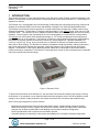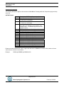
1
ECHOTRAC CV100
USER MANUAL
Version: 4.00
Odom Hydrographic Systems, Inc.
1450 Seaboard Avenue
Baton Rouge, Louisiana
USA
70810-6261
Telephone: (225) 769-3051
Fax: (225) 766-5122
[email protected]
http://www.odomhydrographic.com
Number of pages: 69
Date: February 19, 2008
Echotrac CV100
User Manual
Revision History
Version
3.28
3.28
3.29
Date
12-12-2006
01-10-2007
05-22-2007
Author
S. Apsey
P. Oostenrijk
P. Oostenrijk
4.00
02-19-2008
P. Oostenrijk
Remarks
Initial version - Draft
Updated for release
Added description for Missed Returns on Setup tab.
Minor change in Grey Shades description. Updated
COM port's baudrate options to include 38400.
Removed chapter Overview Parameters and Settings.
This is now refers to the Technical Specification
Ethernet Interface document.
Updated Odom Title and Logo on cover page.
Updated Header and Footer according to new
template.
Updated the introduction section and listed major
changes.
Inserted screen capture of new dialog for selecting a
sounders on the network.
Added Channel signal types and Bandwidth on System
Tab.
Update the NMEA serial output string formats.
Updated uploading firmware and upgrading DSP
firmware.
© ODOM HYDROGRAPHIC SYSTEMS, INC. 2008
All rights are reserved. Reproduction in whole or in part is prohibited without the prior written consent of the copyright owner.
The information presented in this document does not form part of any quotation or contract, is believed to be
accurate and reliable and may be subject to change without notice. The publisher will not accept any liability for
any consequence of its use. Publication thereof does not convey nor imply any license under patent- or other
industrial or intellectual property rights.
Page 2 of 69
Odom Hydrographic Systems, Inc.
February 19, 2008
Echotrac CV100
User Manual
CONTENTS
1
Introduction...................................................................................................................................................... 7
1.1
1.2
1.3
1.4
2
Purpose ....................................................................................................................................................... 8
Scope .......................................................................................................................................................... 8
Glossary ...................................................................................................................................................... 8
References .................................................................................................................................................. 8
Product description......................................................................................................................................... 9
2.1
Specifications .............................................................................................................................................. 9
2.2
Overview ................................................................................................................................................... 10
2.3
Cabling ...................................................................................................................................................... 10
2.4
Power connector ....................................................................................................................................... 10
2.5
Choice of operating frequencies ............................................................................................................... 11
2.6
Signal connector Transducer .................................................................................................................... 11
2.7
Serial Ports................................................................................................................................................ 12
2.8
LAN ........................................................................................................................................................... 12
2.9
Power button ............................................................................................................................................. 12
2.9.1
Power-OFF ........................................................................................................................................ 12
2.9.2
Power-ON .......................................................................................................................................... 12
2.9.3
STANDBY .......................................................................................................................................... 12
2.10
Power indicator...................................................................................................................................... 12
2.11
Ethernet indicators................................................................................................................................. 13
2.12
Transmit indicators ................................................................................................................................ 13
3
Installation...................................................................................................................................................... 14
3.1
Software installation .................................................................................................................................. 14
3.2
Setting up the equipment .......................................................................................................................... 14
3.3
Powering up the equipment ...................................................................................................................... 15
3.4
Transducer installation .............................................................................................................................. 16
3.4.1
“THROUGH HULL” transducer installation ........................................................................................ 16
3.4.2
"SEA CHEST" transducer installation................................................................................................ 17
3.4.3
"OVER-THE-SIDE" transducer installation ........................................................................................ 18
4
Echotrac Control Program............................................................................................................................ 19
4.1
Introduction:............................................................................................................................................... 19
4.2
Important preparation information............................................................................................................. 19
4.3
Starting the Application: ............................................................................................................................ 20
4.4
Basic functionality ..................................................................................................................................... 27
4.4.1
Real-time / Simulator mode (currently not supported)....................................................................... 27
4.4.2
Menu structure ................................................................................................................................... 27
4.4.3
Echotrac control program operation .................................................................................................. 29
4.4.3.1
Setting up Communication ......................................................................................................... 29
4.4.3.2
Enable/Disable Communication ................................................................................................. 29
4.4.3.3
Standby mode............................................................................................................................. 29
4.4.3.4
Standby-Bit ................................................................................................................................. 29
4.4.3.5
Transmit Power........................................................................................................................... 30
4.4.3.6
Receive Gain .............................................................................................................................. 30
4.4.3.7
Alarm........................................................................................................................................... 30
4.4.4
SYSTEM tab ...................................................................................................................................... 31
4.4.4.1
Units............................................................................................................................................ 31
4.4.4.2
Channel ...................................................................................................................................... 31
4.4.4.3
Echo Alarm ................................................................................................................................. 31
Page 3 of 69
Odom Hydrographic Systems, Inc.
February 19, 2008
Echotrac CV100
User Manual
4.4.4.4
Trigger (optional support) ........................................................................................................... 31
4.4.4.5
Ping rate ..................................................................................................................................... 31
4.4.4.6
Maximum depth (Range) ............................................................................................................ 31
4.4.4.7
Blanking ...................................................................................................................................... 32
4.4.4.8
Min. Depth Alarm ........................................................................................................................ 32
4.4.4.9
Language.................................................................................................................................... 32
4.4.4.10 Signal type.................................................................................................................................. 32
4.4.4.11 Bandwidth................................................................................................................................... 32
4.4.5
SETUP tab ......................................................................................................................................... 33
4.4.5.1
Frequency................................................................................................................................... 33
4.4.5.2
TX pulse width ............................................................................................................................ 33
4.4.5.3
TVG curves................................................................................................................................. 33
4.4.5.4
Threshold.................................................................................................................................... 33
4.4.5.5
Min. Gate Width .......................................................................................................................... 33
4.4.5.6
Skip Alarms................................................................................................................................. 34
4.4.5.7
Subbottom Range....................................................................................................................... 34
4.4.5.8
Subbottom TVG .......................................................................................................................... 34
4.4.5.9
Pre Amp Gain ............................................................................................................................. 34
4.4.5.10 Missed Returns .......................................................................................................................... 34
4.4.5.11 Mode .......................................................................................................................................... 34
4.4.6
CALIBRATE tab ................................................................................................................................. 35
4.4.6.1
Draft ............................................................................................................................................ 35
4.4.6.2
Index ........................................................................................................................................... 35
4.4.6.3
Bar depth & Bar width................................................................................................................. 35
4.4.6.4
Sound velocity ............................................................................................................................ 36
4.4.7
CHART tab......................................................................................................................................... 37
4.4.7.1
End-of-Scale & Scale Width ....................................................................................................... 37
4.4.7.2
Scale Change ............................................................................................................................. 37
4.4.7.3
Auto mark every n-seconds........................................................................................................ 38
4.4.7.4
Digitizer Line ............................................................................................................................... 38
4.4.7.5
Heave correction......................................................................................................................... 38
4.4.7.6
Plot Gate..................................................................................................................................... 38
4.4.8
COMMUNICATIONS tab ................................................................................................................... 39
4.4.8.1
COM 1 Outputstring.................................................................................................................... 39
4.4.8.2
COM 2 Remote Display .............................................................................................................. 39
4.4.8.3
COM 3 GPS input selection........................................................................................................ 39
4.4.8.4
COM 4 Heave input selection..................................................................................................... 39
4.4.8.5
COM port Baud rates.................................................................................................................. 39
4.4.9
DIAGNOSTIC tab............................................................................................................................... 39
4.4.9.1
Simulator mode (currently not supported) .................................................................................. 39
4.4.9.2
COM test (currently not supported) ............................................................................................ 39
4.4.9.3
Version........................................................................................................................................ 39
4.4.10
Menu options.................................................................................................................................. 40
4.4.10.1 Load Settings (FILE) .................................................................................................................. 40
4.4.10.2 Save Settings (FILE) .................................................................................................................. 40
4.4.10.3 Load Port/IP settings (FILE)....................................................................................................... 40
4.4.10.4 Save Port/IP settings (FILE)....................................................................................................... 40
4.4.10.5 Exit (FILE) .................................................................................................................................. 40
4.4.10.6 Open Connection (CONTROL) .................................................................................................. 40
4.4.10.7 Close Connection (CONTROL).................................................................................................. 40
4.4.10.8 Go to Standby (CONTROL) ....................................................................................................... 40
4.4.10.9 ET startup loaded (CONTROL).................................................................................................. 40
4.4.10.10 ET default settings (CONTROL) .............................................................................................. 41
4.4.10.11 Depth monitor (CONTROL)...................................................................................................... 41
Page 4 of 69
Odom Hydrographic Systems, Inc.
February 19, 2008
Echotrac CV100
User Manual
4.4.10.12
4.4.10.13
4.4.10.14
4.4.10.15
5
Set Time and Date (CONTROL) .............................................................................................. 41
Dynamic scroll buttons (CONTROL) ........................................................................................ 41
Changing parameter values ..................................................................................................... 41
Connection (INFO) ................................................................................................................... 42
Operational procedures ................................................................................................................................ 43
5.1
5.2
5.3
5.4
6
Things to consider when calibrating.......................................................................................................... 43
How to calibrate the Echotrac CV ............................................................................................................. 43
How to perform a bar check ...................................................................................................................... 45
Shallow Water Operation .......................................................................................................................... 46
Troubleshooting ............................................................................................................................................ 47
6.1
6.2
6.3
6.4
6.5
6.6
6.7
7
Problems installing the Echotrac CV Windows application....................................................................... 47
How to copy the Echotrac CV windows installation files to disk ............................................................... 47
The Echotrac CV does not seem to be working........................................................................................ 48
The Echotrac CV power LED is off ........................................................................................................... 48
The Echotrac CV power LED is flickering ................................................................................................. 48
What are the COM-port settings ............................................................................................................... 48
Known problems with Transducer............................................................................................................. 48
Technical specifications ............................................................................................................................... 49
7.1
Computer communications ....................................................................................................................... 49
7.2
Overview Serial Output string formats ...................................................................................................... 50
7.3
Serial output strings .................................................................................................................................. 52
7.3.1
Echotrac SBT..................................................................................................................................... 52
7.3.2
Echotrac DBT..................................................................................................................................... 53
7.3.3
Heave................................................................................................................................................. 55
7.3.4
DESO25 ............................................................................................................................................. 56
7.3.5
DESO DDV ........................................................................................................................................ 56
7.3.6
DESO COMMANDS .......................................................................................................................... 57
7.3.7
NMEA DBS ........................................................................................................................................ 57
7.4
Serial Data input / Chart annotation.......................................................................................................... 58
7.5
Serial heave input ..................................................................................................................................... 59
7.6
External Serial Control of Echotrac Parameters ....................................................................................... 60
8
Overview parameters and settings.............................................................................................................. 62
8.1
9
External Ethernet Control of Echotrac Parameters................................................................................... 62
Uploading Firmware ...................................................................................................................................... 63
9.1
9.2
10
10.1
10.2
10.3
10.4
10.5
10.6
10.7
Upgrading Motorola Processor Firmware ................................................................................................. 63
Upgrading DSP Firmware ......................................................................................................................... 64
Echotrac CV Cable Connections.............................................................................................................. 65
Serial 1................................................................................................................................................... 65
Serial 2................................................................................................................................................... 65
Serial 3................................................................................................................................................... 65
Heave .................................................................................................................................................... 65
LAN........................................................................................................................................................ 65
Transducer............................................................................................................................................. 66
DC.......................................................................................................................................................... 66
Appendix A. CABLE CONNECTIONS: ................................................................................................................. 67
Appendix B. Quick Start Operating Procedures ................................................................................................ 68
Page 5 of 69
Odom Hydrographic Systems, Inc.
February 19, 2008
Echotrac CV100
User Manual
Page 6 of 69
Odom Hydrographic Systems, Inc.
February 19, 2008
Echotrac CV100
User Manual
1 INTRODUCTION
There are four Echotrac CV units named Echotrac CV100, Echotrac CV200, Echotrac CV300 and Echotrac CVM
(Mobile). This document covers the Echotrac CV100 and will refer to this unit as “Echotrac CV”. This Echotrac CV
supports one channel.
The Echotrac CV is a hydrographic echo sounder design incorporating the cutting-edge technology, features and
reliability of the Echotrac MKIII, plus the ease and flexibility of operation of a networked Windows® interface.
The Echotrac CV transceiver units are supplied in a compact stand-alone package that is ideally suited to many
shipboard installations. The Echotrac CV supports Chart-functionality in one optional format, a full size color LCD
“electronic chart”. The “electronic chart” is supplied in flexible modular enclosures complete with swivel mounting
hardware. A second option, that of operating the unit and collecting data on a networked PC, is also possible.
The optional color LCD module offers internal data storage (in .XTF format) and playback of the analog return
signal digitized to full 16-bit resolution. The Echotrac CV features a robust design and frequency agility enabling
the operator to precisely match the transceiver to almost any existing transducer. Operator selectable TVG
curves (10 Log, 20 Log, 30 Log, 40 Log, and Off) serve to optimise the Echotrac for shallow bottom detection
tasks and for Sonar imaging. The Echotrac CV features unsurpassed interfacing flexibility, offering 4 serial ports
that can be configured to interface with computers, positioning systems, motion reference units and remote
displays. The Echotrac CV also has an Ethernet port that outputs the 16 bit samples of the acoustic data for
further processing or visualization. The Echotrac CV also supports a number of output formats that are compatible
with most common Echo Sounder strings.
Figure 1: Echotrac CV100
To learn about the features of the Echotrac CV, this document is structured as a step by step manual; covering
the Echotrac CV as a product, how to install the software and the equipment, how to use all the different control
settings, how to perform certain procedures, how cables are wired to their connectors and troubleshooting.
Some of the major changes as of version 4.00 are:
-
Replacement of the Echotrac Control Program with Odom eChart, a graphical data acquisition program.
Because the Echotrac Control Program 4.00 will become obsolete, it does not support some of the major
changes such as faster synchronization and adapting to the sounder’s hardware configuration.
Faster synchronization due to improved communication protocol.
Automatic detection of sounder(s) on the network and adapting to the sounder’s hardware configuration.
Page 7 of 69
Odom Hydrographic Systems, Inc.
February 19, 2008
Echotrac CV100
User Manual
1.1
Purpose
The purpose of this document is to explain the features and operation of the Echotrac CV.
1.2
Scope
The content of this document is focused on the end-user.
1.3
Glossary
DBS
DBT
DGPS
DSP
ETCV
NMEA
SBT
TNC
TVG
VDC
Depth Below Surface
Dual Bottom Tracking
Differential Global Positioning System
Digital Signal Processor
Echotrac CV
National Marine Electronics Association
Single Bottom Tracking
Threaded Nut Connector
Time Varied Gain
Volts Direct Current
1.4
References
[1]
Title:
Author(s):
Report no:
Version:
Date:
Windows Flash Utility: OdomFlash.exe
Patrick Oostenrijk
N/A
2.2
2007-02-27
[2]
Title:
Author(s):
Report no:
Version:
Date:
Using Echotrac Ethernet Driver with Hypack
Stephen Apsey
N/A
1.0
2006-07-17
[3]
Title:
Author(s):
Report no:
Version:
Date:
Technical Specification Ethernet Interface
Patrick Oostenrijk
N/A
1.3
2007-05-22
Page 8 of 69
Odom Hydrographic Systems, Inc.
February 19, 2008
Echotrac CV100
User Manual
2 PRODUCT DESCRIPTION
2.1
Specifications
Frequency
•
High Band: 100 kHz-750 kHz
•
Low Band: 24 kHz-50 kHz
Output Power
•
Up to 200 watts RMS
Input Power
•
12 to 24 VDC 30 watts
Resolution
•
0.01m / 0.1 ft.
Accuracy
•
0.01m / 0.10 ft. +/- 0.1% of depth @
200 kHz
•
0.10m / 0.30 ft. +/- 0.1% of depth @
33 kHz
Depth Range
•
0.2 – 600m / 0.5 – 600 ft.
Chart Scales
•
5,10,20,40,80,100,200,400,800m
•
15,30,60,120,240,300,600,1200,
2400ft.
Phasing
•
Automatic scale change, 10%,20%,
30% overlap or Manual
LCD Display
•
15 inch TFT Screen
•
Sunlight Readable
•
Internal Data Storage in XTF format
on 40GB Hard Disk
•
Data Transfer via Ethernet interface
or USB Flash Drive
Sound Velocity
•
1370 – 1700 m/s
•
Resolution 1 m/s
Transducer Draft Setting
•
0 – 15m (0 – 50 ft.)
Depth Display
•
On control PC and LCD display
Clock
•
Internal battery backed time,
elapsed time, and date clock
Annotation
•
Internal – date, time, GPS position
•
External – from RS232 port
Interfaces
•
4 x RS232 and 1 x RS422 serial
ports, baud rate selectable 480019200.
•
Inputs from external computer,
motion sensor, sound velocity.
•
Outputs to external computer,
remote display
•
Outputs with LCD chart – VGA
video out
•
Ethernet interface
•
Heave – TSS1 and sounder
sentence
Blanking
•
0 to full scale
Installation
•
Desktop
Software
•
Echotrac Control supplied
•
ChartView supplied with LCD
configuration
Environmental Operating Conditions
•
0°– 50° C, 5 – 90% relative
humidity, Non-condensing
Dimensions
•
28cm (11”) x 23cm (9”) W x
11.5cm (4.5”) D
Weight
•
5 kg (11 lbs.)
Options
•
Remote Display
•
Side Scan Transducer – single or
dual channel side looking 200 kHz
for 340kHz for search and
reconnaissance
Page 9 of 69
Odom Hydrographic Systems, Inc.
February 19, 2008
Echotrac CV100
User Manual
2.2
Overview
On the backpanel of the Echotrac CV are all the connectors for serial communication interfacing, GPS data,
Ethernet communication, Transducer signals and power. See below, in Figure 2 for an overview of all the
connectors. Each item will be explained in more detail in the following chapters. The front panel has LED
indicators for Ethernet communication, Transceiver board operation and power.
Serial 1
Serial 3
Serial 2
Heave
Transmit
LED
Transducer
12-24
VDC
Power
Button
Power
LED
LAN
LAN Status
LED
Figure 2: Overview of Echotrac CV
The Echotrac CV is a flexible unit designed for tabletop. Rack mounting can be accommodated with the included
special hardware. Where tabletop mounting is preferred, it is highly recommended that the unit be secured with
external 'tie-downs' for rough seas or heavy swells.
2.3
Cabling
All cabling is via the connectors located in the recessed panel at the rear of the unit. A view of the connector
arrangement is shown in Figure 2. Cable details are given in Appendix A. Care should be taken to route cables
using horizontal and vertical runs wherever possible. Avoid paths that run adjacent to transmitter feeder cables or
close to heat radiating elements such as steam pipes. For permanent installations, cables should be clamped at
regular intervals (1m) along their complete lengths.
2.4
Power connector
The Echotrac CV can be powered by DC power sources. DC operation requires an input voltage between 11 and
29 VDC (nominal 24 VDC). Average power consumption is approximately 25-30 watts. Frequently, power is
derived from two 12 V lead-acid batteries connected in series. These batteries (24V configuration), fully charged,
and in good condition, can normally power a unit for a full day without re-charging. Regulated DC supplies should
be able to source a short duration in-rush current spike of approximately 6 amps and an average current load of 3
amps. In the case of "charger" type (unregulated) supplies, the output should be "floated" across a battery load
and not connected solely to the echo sounder’s DC input. Details of the power cable are given in Appendix A.
Should the DC input voltage polarity be applied in reverse, an audible alarm within the unit will sound regardless
of the POWER switch setting. In the event that the input voltage drops below the minimum threshold the unit will
automatically shut down.
Page 10 of 69
Odom Hydrographic Systems, Inc.
February 19, 2008
Echotrac CV100
User Manual
Setting up two batteries in series (24 Volts DC system)
DC Power cable
(-)
(+)
Battery 1
12 Volts
(-)
Jumper
(+)
Battery 2
12 Volts
Using a jumper simply connect the positive post of battery 1 to the negative post on battery 2. Connect the
negative lead from the power cable to the negative post on battery 1 and the positive lead to the positive post on
battery 2. Always check the voltage with a voltage or multi-meter before connecting the DC power cable to any
equipment. Make sure that all the connecting equipment is also turned off before applying the power cables.
Otherwise the transients of such a ‘jump-start’ could damage the equipment.
2.5
Choice of operating frequencies
The Echotrac CV can be configured to use either a High or a Low frequency board, respectively 100 kHz – 750
kHz or 24 kHz – 50 kHz. Standard transducers are generally available from stock that support the frequency
ranges listed on the product description page (See 2.1 Specifications).
2.6
Signal connector Transducer
The signal from the transducer is passed to the Echotrac CV via a standard Odom transducer cable with a twistlock connector.
Page 11 of 69
Odom Hydrographic Systems, Inc.
February 19, 2008
Echotrac CV100
User Manual
2.7
Serial Ports
Serial 1
The Echotrac CV uses Serial port 1 to output depth data. Using a special Flash Utility program, the port is also
used to upgrade the software in the Echotrac CV. Another use of the port is to send commands to the Echotrac
CV or request certain parameter settings.
Serial 2
Serial port 2 is dedicated to connect the optional remote display to the Echotrac CV. The port can be configured
to use either an RS232 or RS422 protocol.
However, this feature is currently not supported with the Echotrac CV.
Serial 3
Serial port 3 is used to receive external GPS data in NMEA GLL or GGA format. It is best to only configure the
GPS to output only one of these strings as too much data can interfere with the communication processor’s other
tasks. When a GPS is connected to the Echotrac CV and is receiving position information, the Echotrac CV
100can output that GPS information on the Ethernet port.
Heave
Serial port 4 is used to receive motion sensor data in TSS1 format (heave). This port enables the Echotrac CV to
accept data from a motion compensator to apply corrections for the vertical movement caused by swells. The
Echotrac CV will only correct the depth for Heave. No corrections are done for Roll and Pitch.
2.8
LAN
The LAN port is used by the Echotrac CV to send and receive data on the network. The Echotrac CV can be
connected directly to a Hub or a Switch using a regular UTP CAT-5 ethernet cable. A regular cable is also known
as a ‘straight’ UTP cable. When the Echotrac is connected directly to a computer, a so-called ‘cross-over’ UTP
cable must be used. When a computer is directly connected to the Echotrac CV using a crossover cable, the
operating system on the computer may take 2-3 minutes before the computer has accepted a valid IP address. To
prevent this delay, you can assign the computer a static IP address or use a Hub/Switch.
2.9
Power button
The power switch in the ON position will power-up the internal circuitry. In the OFF position it will power-down the
internal circuitry.
2.9.1
Power-OFF
The main power switching circuitry is open in this position.
2.9.2
Power-ON
On "power-up", the unit performs a Self-test to check system memory and also tests the Non-volatile RAM battery
voltage. If there was a problem with the Non-volatile RAM, the factory defaults will be loaded. The unit then enters
the sounding mode and begins data acquisition.
2.9.3
STANDBY
The main power circuitry is energized, drawing current from the mains and providing regulated DC voltages to all
internal modules. The unit is no longer in the sounding mode when it is in the standby position. However, the
Parameter Entry System is enabled.
2.10 Power indicator
When the Echotrac CV is turned on, a red LED will be on to indicate that the internal systems have powered up
successfully. The red LED is located below the power button.
Page 12 of 69
Odom Hydrographic Systems, Inc.
February 19, 2008
Echotrac CV100
User Manual
2.11 Ethernet indicators
The TX indicator on the Echotrac CV indicates whether or not the data is transmitted on the Ethernet port. The
frequency at which the TX indicator flickers also indicates whether the Echotrac CV is outputting data at a slow or
fast pace.
The Link indicator on the Echotrac CV indicates that it recognizes the presence of a network. If the receiving end
of the ethernet cable is connected to a computer or a hub/switch that is not powered on, the link light will not be
on.
2.12 Transmit indicators
The Transmit indicators on the Echotrac CV indicate whether the Transducer is firing or not. The frequency at
which the Channel indicator flickers also indicates whether the Transducer is firing at a slow or fast pace.
Page 13 of 69
Odom Hydrographic Systems, Inc.
February 19, 2008
Echotrac CV100
User Manual
3 INSTALLATION
This section contains the information necessary to install the Echotrac Control Software, power-up and connect
the Echotrac CV. The installation procedure consists of a number of steps. Each step corresponds to a specific
chapter. It is recommended that these steps (chapter 3.1, 3.2 and 3.3) for the installation procedure be followed in
this order. See also the quick start procedure in Appendix B.
3.1
Software installation
The minimum requirements for a personal computer to install and run only the Echotrac Control software are:
• Windows 98
• Pentium-I, running at 200 MHz
• 32 Mb of internal memory
• 10 Mb of free space on the harddrive
• One COM-port
The Echotrac control program is fully tested on the following Operating Systems:
• Windows 98
• Windows 2000
• Windows XP
• Windows NT
Note: Windows ME is not supported.
Note: A minimum of two COM-ports are needed to run: one port to receive serial data from the Echotrac and
communicate with the Echotrac, and one port to receive GPS. This is an example of a situation when ethernet
cannot be used.
The software that is shipped with the unit can be installed on the personal computer by executing the program
called SETUP.EXE. This program will install the Echotrac Control software in the Program Files directory. During
the setup process it is possible that Windows will ask if you wish to keep certain files on the computer that are
older or newer than the ones being installed. By default it is advised to keep the files that are currently on the
computer to avoid any conflicts or problems with other programs. If during the setup process, the setup program
cannot find the files on your computer that it needs to install the Echotrac CV, the missing file(s) will be copied
onto the hard drive.
3.2
Setting up the equipment
The Echotrac CV is a lightweight unit designed for portability. An interconnection diagram is shown in Figure 3.
Care should be taken to route cables using horizontal and vertical runs wherever possible. Avoid paths that run
adjacent to transmitter feeder cables or close to heat radiating elements such as steam pipes. For permanent
installations, cables should be clamped at regular intervals (3 feet or 1 meter) along their complete lengths.
The Echotrac CV requires either an input voltage between: +11 and +29 VDC (standard). The unit consumes
less than 30 watts of power in normal operation. Power is frequently derived from one or two 12 V lead-acid
batteries. Two batteries (24V configuration), fully charged, and in good condition, can normally power a unit for a
full day without re-charging. Details of the power cable are given in the chapter 2.4 Power connector and the
Appendix .
All cables are attached to the connectors located in the recessed area at the left rear of the unit (See Figure 2 in
chapter 2.2). Connections are made through multi-pin “MS” style connectors, between the Echotrac CV, its power
source, the transducer and all computer or peripheral devices.
The following Interconnection block diagram shows everything that can be connected to the Echotrac CV. All
these peripherals are not required to use the basic functionality of the Echotrac CV.
Page 14 of 69
Odom Hydrographic Systems, Inc.
February 19, 2008
Echotrac CV100
User Manual
Motion Sensor (Heave)
f
Optional External GPS (COM3)
e
g
ECHOTRAC
CV100
a/d
c
Power
Remote Display (COM2)
control (COM1)
Computer
b
Transducer
Figure 3: Interconnection block diagram
Before connecting any of the cables, make sure that the computer, the Echotrac CV and other peripherals are
turned off. The list below is a sequence of steps for connecting the Echotrac CV with the computer and GPS. If
any problems arise, see the Troubleshooting section.
a) Connect the RS232 cable between the computer and the DB9 connector labeled “Serial 1”, if you need to
collect depth data through the serial port or need to send command to the Echotrac CV.
b) Connect the cable from the Transducer to the connector on the Echotrac CV labeled “Transducer”.
c) Connect the power cable for the Echotrac CV to the connector labeled “POWER”.
d) Connect the UTP ethernet cable to the LAN connector if you want to collect data across a network.
If an external peripherals are used, then:
e) Connect the RS232 cable between the connector labeled “Serial 3” and the external GPS.
f) Connect the RS232 cable between the motion sensor and the connector labelled “Heave”.
g) Connect the RS232 cable between the remote display and the connector labelled “Serial 2”.
3.3
Powering up the equipment
The following sequence must be followed when powering up the equipment:
1. Turn on the personal computer.
2. Turn on the Echotrac CV. After turning the Power Switch from the OFF position to ON, confirm that the power
LED, Ethernet Link LED come on. After a few seconds, the Ethernet TX/RX LED and one or both of the
Transmit High / Low LEDs should start blinking.
3. Start the Echotrac CV Window Application program.
4. Turn on optional peripherals such as GPS or motion sensor.
5. Depending on water depth and bottom type, set the Tx Power to mid-range (position 6) in the Echotrac control
program.
6. Set the RxGAIN to about halfway on the maximum scale.
7. Adjust RxGAIN and TxPOWER to get a clear strong record with few alarms on the displayed depth.
Note: The Echotrac CV should always be turned on before running the Echotrac control program.
Note: Should you feel that a return to the sounder’s default parameter values is called for, then select the Default
Reset option in the Echotrac CV Window Application program.
Page 15 of 69
Odom Hydrographic Systems, Inc.
February 19, 2008
Echotrac CV100
User Manual
3.4
Transducer installation
Proper mounting of the transducer is a crucial part of the installation of any "survey" echo sounder. An improperly
mounted transducer will result in poor system operation and unacceptable data quality.
Important: See also chapter 6.7 Known problems with Transducer.
In the case of temporary installations, the transducer is often mounted over-the-side. In permanent installations
and "pay surveys," hull mounts are generally preferred and often required. In either case, the transducer should
be mounted as far below the waterline as possible. In cases where "over the side" mounts are exposed to wave
action, ensure that the transducer is mounted far enough below the surface so that it remains well submerged
during vessel roll motions.
A preferred mounting location is near the keel of the vessel, in an area where the planing attitude of the hull and
the pitch and roll angles of the vessel have the least effect at operating speed. The transducer should be
mounted far enough aft of the bow so that bubbles generated by the bow wave will not pass over the face of the
unit. Transducers should be located away from sources of turbulence and cavitation bubbles such as propellers,
bow thrusters and hull protrusions. Consideration should also be given to sources of mechanical noise generated
within the vessel (engines, propellers, pumps, generators, etc.). In some severe cases of mechanically coupled
noise, vibration-isolating mounts may be required to mechanically decouple the transducer from the hull.
Transducer mounting can be accomplished in many different ways. The following three chapters show common
configurations.
3.4.1
“THROUGH HULL” transducer installation
The top side of the transducer is accessible from inside the vessel while the transducer face is directly exposed to
the water. Care should be taken to protect the transducer from damage and turbulence by installing a fairing with
a sloping forward edge ahead of the unit. The fairing has the dual effect of both minimizing possible strike
damage and smoothing the flow of water over the face of the transducer.
Figure 4: Transducer mounted through the hull
Page 16 of 69
Odom Hydrographic Systems, Inc.
February 19, 2008
Echotrac CV100
User Manual
3.4.2
"SEA CHEST" transducer installation
In a "sea chest" mount, a fluid-filled enclosure large enough to contain the entire transducer is attached to the
outer hull of the vessel. The outer hull is removed within the area of the chest and replaced with an acoustically
clear "window" which is mounted flush with the hull surrounding the chest. Depending on construction, the
material selected for the acoustic window, and the draft of the vessel, access can often be gained to the
transducer from inside the hull without putting the vessel in dry-dock. In most installations, a water-filled
standpipe is incorporated into the "sea chest" design in order to provide hydrostatic pressure equalization.
Transducer cables generally leave these assemblies through stuffing tubes, which maintain the watertight integrity
of the chest.
Page 17 of 69
Odom Hydrographic Systems, Inc.
February 19, 2008
Echotrac CV100
User Manual
3.4.3
"OVER-THE-SIDE" transducer installation
A mount of this type is frequently constructed from a length of pipe. This fixture should be sized to position the
transducer well below the waterline and the pipe then fixed to a sturdy support on the vessel. Lines generally are
attached at the transducer pipe and tied off fore and aft in order to maintain a stable, horizontal transducer
attitude. Care should be taken to assure adequate protection for the transducer cable, particularly at the point
where the cable leaves the transducer body.
In all of the above installations, particular care should be taken to assure that the transducer radiating face
remains as parallel to the water surface as much as possible while the vessel is moving.
Page 18 of 69
Odom Hydrographic Systems, Inc.
February 19, 2008
Echotrac CV100
User Manual
4 ECHOTRAC CONTROL PROGRAM
4.1
Introduction:
This section contains the information necessary to operate the Echotrac CV using the Echotrac control program.
The Echotrac control program is developed to provide the operator with complete control over the Echotrac
models.
4.2
Important preparation information
There are several gradations of preparation and this section will describe the bare minimum and a fully equipped
survey preparation. Allow yourself at least one full day to setup and familiarize yourself with the equipment and
software that you are going to use. This includes computers, GPS, motion sensors, transducers, network hubs
and cables and third party programs.
First, setup your computer and Echotrac CV in a comfortable environment to avoid troubleshooting out in the field.
At this point you do not need any other equipment. If problems or questions should arise, access to the Internet
and a land line (telephone) will be beneficial for Odom Hydrographic System engineers to provide good support.
Follow the Quick Start operating procedures in Appendix B that basically instruct you to power on the Echotrac
CV, install the Echotrac Control program and communicate with the Echotrac CV.
The Echotrac CV is shipped with a CD-ROM containing the latest version of software. There is a setup.exe that
will install the control program for the Echotrac CV.
Once the software is installed, connect all hardware including power to the echo sounder. Use the red Ethernet
crossover cable supplied with your system purchase.
Switch the Echotrac CV and computer power from OFF to ON.
Confirm that the power LED and Ethernet Link LED on the unit come on. By factory default the Echotrac comes
up in Standby and the Echotrac Control program is needed to start the echo-sounder. When that happens, the
Ethernet TX/RX LED should start blinking. When the synchronization has been completed, one or both of the
Transmit High / Low LEDs should start to blink.
The Echotrac control program may require about three minutes to receive the network settings from Windows.
The fully equipped preparation involves connecting the GPS and motion sensor to the Echotrac CV. If possible
that transducer can also be connected to the Echotrac CV. The transducer can be temporarily suspended in a
bath or large bucket of clean water. Make sure that the transducer face is clean. See also chapter 6.7 Known
problems with Transducer.
Check the GPS settings such as the output string type (GLL, GGA), speed and the baud rate. Once you have the
equipment connected you can check to see if the information from the GPS, Echotrac CV and motion sensor are
correctly logged or displayed in the respective applications. The Echotrac Control Program only shows the depth.
Other programs will show the analog and digitized signal as well as the GPS and motion sensor information that
is processed by the Echotrac CV.
Once you have become familiar with the equipment and programs you can setup everything on the vessel.
Perform the same preparation steps on the vessel before going out on a survey. It is possible that the new
environment ( the vessel ) introduces unforeseen problems such as power surges from generators or electro
magnetic noise from engines. It is important to realize that there are a multitude of sources that could possibly
introduce problems.
Page 19 of 69
Odom Hydrographic Systems, Inc.
February 19, 2008
Echotrac CV100
User Manual
4.3
Starting the Application:
If you have not yet installed the Echotrac Control program, then install that now. See chapter 3 Installation for
more information. If you have problems with the installation see the Troubleshooting chapters 6.1 and 6.2.
After the Echotrac control software has been installed the windows application can be found at the following
location (See also Figure 5 below):
Click on START at the task bar (the start menu will appear).
Go to the menu item named Programs (a submenu will automatically appear).
Go to the menu item named Echotrac CV in that submenu (another submenu will appear).
Click on the menu item Echotrac CV in that submenu.
The Echotrac control program for Windows will now start with a so-called Splash screen as shown in Figure 6.
The splash screen shows the version number and date of the Echotrac Control program.
When the progress bar on the Splash screen has reached the end, the Target Selection window will appear
(Figure 7). In this window you select the Echotrac that you are going to use. After the target has been selected the
Main screen will appear as shown in Figure 9.
The Echotrac control program is now ready to be used.
Figure 5: Echotrac CV location in Windows menu
Page 20 of 69
Odom Hydrographic Systems, Inc.
February 19, 2008
Echotrac CV100
User Manual
The figure below shows the Splash screen when the Echotrac Control program starts. It shows the contact
information for Odom Hydrographic Systems and also the program’s version number and release date. The latter
should be used to determine whether you have an up-to-date program.
Figure 6: Echotrac CV Splash screen
The following screen is displayed when the splash screen disappears. and the Echotrac Control program was
unable to automatically detect any sounders on the network. Automatic detection is supported from firmware 4.00
and higher. This screen allows you to select the target unit that you will be controlling with the Echotrac Control
program. Selecting the wrong target unit will result in certain features not being supported or problems with
communication between the Echotrac CV, the Echotrac Control program and/or third party programs.
Figure 7: Select Echotrac Model
Page 21 of 69
Odom Hydrographic Systems, Inc.
February 19, 2008
Echotrac CV100
User Manual
The following screen is displayed when the splash screen disappears and the Echotrac Control program was able
to automatically detect any sounders on the network. Automatic detection is supported from firmware 4.00 and
higher. This screen allows you to select the target unit that you will be controlling with the Echotrac Control
program. The screen also shows any additional information that you may need to know when support from a
technician is required. For example to verify firmware upgrade options.
Figure 8: Select Echotrac Model
Page 22 of 69
Odom Hydrographic Systems, Inc.
February 19, 2008
Echotrac CV100
User Manual
The following figure shows the main screen of the Echotrac Control program. If a different target unit is selected
the main screen may look different. For example, the Echotrac CV3 supports a third channel and the MK3
supports extra printer features such as Paper Feed and Chart Start and Stop controls.
Figure 9: Echotrac CV main screen
The first step to perform after the Echotrac Control program has started is to check whether or not the program
has detected any network settings. The Echotrac Control program uses the network card in the computer and a
network cable to communicate with the Echotrac CV.
The Channel 1 signal types (Envelope, Half Wave AC and Full Wave AC) and Bandwidth are only supported by
the new low frequency board with firmware 4.00.
From the Main window, go to the menu item labeled Info and then select the menu option Connection as shown
in the figure below.
Page 23 of 69
Odom Hydrographic Systems, Inc.
February 19, 2008
Echotrac CV100
User Manual
Page 24 of 69
Odom Hydrographic Systems, Inc.
February 19, 2008
Echotrac CV100
User Manual
If your Connection Info window looks similar to the following example, then the Echotrac Control program has
accepted the local host IP address that was provided by Windows.
Example of a valid network
IP address when using a
cross-over UTP cable (This
should be a red cable
provided with the Echotrac
CV).
The first two numbers are
always 169.254. The latter
two numbers may vary as
shown on the left.
If you use a regular network
cable (This should be a blue
cable provided with the
Echotrac CV) then the
network IP address may be
different. Eg. 192.168.43.12
or 140.90.120.2.
If you do not have proper
network IP address, you will
see an IP address as shown
on the left. If this happens,
exit the software, wait about
three minutes and restart the
Echotrac Control program. It
means that Windows has not
yet determined an IP
address for applications to
use. OR there is no network
detected at all.
Make sure the Ethernet
cross-over cable is
connected correctly from the
Echotrac CV to the PC.
Page 25 of 69
Odom Hydrographic Systems, Inc.
February 19, 2008
Echotrac CV100
User Manual
Once you have a correct IP address, go to the Control menu and click on Open Connection.
The Echotrac control program will first try to connect to the network. When the network settings have been
verified, it will try to synchronize with the Echotrac.
If you see a message appear as shown on the right,
then that means that Windows has not yet determined
a valid network IP address.
Exit from the software and wait for about three minutes.
Windows should then have determined the correct
network settings.
The message on the right will appear each time the
Ethernet connection with the Computer has been
interrupted. For example: Ethernet cable was
disconnected or Echotrac CV was powered off.
Page 26 of 69
Odom Hydrographic Systems, Inc.
February 19, 2008
Echotrac CV100
User Manual
4.4
Basic functionality
4.4.1
Real-time / Simulator mode (currently not supported)
The Echotrac CV supports two modes:
• Real Time Acquisition
• Simulator mode (currently not supported)
During Real Time Acquisition the Echotrac CV processes the analog signal from the transducers and outputs data
on the Serial 1 port and the LAN port. The Echotrac control program displays the data on the screen.
When the Echotrac CV is in Simulator mode, the data will be generated by the Echotrac CV.
4.4.2
Menu structure
The application provides a menu with the following four main categories: FILE, CONTROL, INFO and HELP.
Each category can be accessed by either clicking on it with the left mouse-button or by pressing the keycombination ALT+<underlined letter>.
File
Control
(ALT+F)
(ALT+C)
Info
(ALT+i)
Load Settings (CTRL+L)
Open Connection
Connection
Save Settings (CTRL+S)
Close Connection
Datacheck
Load Port/IP settings
Goto Standby
Save Port/IP settings
ETCV startup Loaded
Exit
ETCV default settings
(CTRL+X)
Help (ALT+H)
About
Depth Monitor
Set Time and Date
Dynamic Scroll buttons
Figure 10: Menu structure
The item EXIT under the FILE menu will close the Echotrac control program.
The item LOAD SETTINGS loads Echotrac CV settings from a previously saved file. Load the settings after the
synchronization procedure has been completed.
The item SAVE SETTINGS saves the current Echotrac CV settings to a file. You can do this at any time. You do
not need to synchronize with the Echotrac CV first.
The item OPEN CONNECTION under the Control menu will setup the communication protocol through the
network with the Echotrac CV and download the Echotrac CV’s current settings to the control program.
The item CLOSE CONNECTION terminates the communication with the Echotrac CV through the network.
The item GOTO STANDBY will put the Echotrac CV in Standby mode.
The item ETCV STARTUP LOADED indicates when all the settings from the Echotrac CV have been received.
The item ETCV DEFAULT SETTINGS will send the default settings to the Echotrac CV.
The item DYNAMIC SCROLL BUTTONS allow the user to have larger scroll-buttons when the user clicks on a
field.
Page 27 of 69
Odom Hydrographic Systems, Inc.
February 19, 2008
Echotrac CV100
User Manual
The item DEPTH MONITOR will display an extra window that can be locked onto the desktop and remain visible
for as long as the Echotrac Control program is running. This window displays the depths and units just like the
main window does. The advantage of this window is that when another application is running the Echotrac CV
main control window does not need to be visible to see the depths.
The item Set Time and Date is used to send the current computer time and date to the Echotrac CV. This feature
can be used when the internal clock of the Echotrac CV is not correct.
The item CONNECTION under the Info menu will display the ports used by the communication protocol.
The item DATACHECK will allow you to verify if the Echotrac CV is outputting GPS and/or Heave data after you
have successfully synchronized communication with the Echotrac CV.
The item ABOUT under the HELP menu will display information about the Echotrac CV and the Echotrac control
program.
The figure below shows the channels that the Echotrac CV is able to support. When the button with the pin is
clicked, the pin will be displayed as if it’s ‘pinning’ the window down to the desktop. The window is now locked and
will remain visible on top of any other programs.
The Echotrac CV100 does not support an external Odom printer and therefore the buttons for Mark, Chart On/Off,
Paper Feed and Print parameters are not displayed. There is also an Alarm indicator to display relatively how
many pings have been missed.
The Back and Next buttons will change the Depth monitor window to display the Gain and Power controls. Hereby
the main Echotrac Control Program need not remain visible at all times, allowing you to use other programs for
Data collection and maximize the majority of the screen.
The slider offers an alternative solution if you would like to keep the Echotrac Control Program visible as well as
the program for data collection. The slider sets the transparency of the Echotrac Control window. This window
remains on top of the program collecting the data, but because you can see through it allows you to see the data
and still be able to use the Echotrac Control program at the same time. See example below.
Page 28 of 69
Odom Hydrographic Systems, Inc.
February 19, 2008
Echotrac CV100
User Manual
4.4.3
Echotrac control program operation
The Echotrac CV should always be powered-up before starting the Echotrac control program. The application is
ready to be used when the main screen is displayed. Any parameter changes made in the application will be
stored in the Windows Registry so that the next time the application is started the previous settings will be loaded.
This allows you to always have a record of your most recent settings that you were using. You can save these
settings to a file for later use. When the Echotrac control program synchronizes with the Echotrac, the Echotrac
will send all its current settings to the Echotrac control program and override any current settings. The first time
the application is installed on the computer and started; the default parameter settings will be applied.
4.4.3.1 Setting up Communication
Before enabling the communication between the Echotrac CV and the Echotrac control program, the connection
settings must be checked. The connection settings can be found under the Info menu. If the Local Host’s IP
Address is 127.0.0.1, then the operating system has not acquired an IP Address. You can try and open a
connection with the Echotrac CV, but it may take a minute or two before a network connection is allowed by
Windows. If the network check fails and there is still no IP address, then check to see if the Echotrac’s LINK
indicator is on. If the LINK indicator is not on, then there is a problem with connecting the network. Check all the
network cables.
When the Echotrac Control Program detects that Windows has acquired a valid IP address, it will continue with
the Synchronization process The Open Connection item can be found under the Setup menu. The Echotrac
control program will now setup a communication protocol with the Echotrac CV and synchronize all the Echotrac
CV’s settings with the control program.
4.4.3.2 Enable/Disable Communication
Each time the Echotrac control program opens a connection, it will synchronize all the settings with the Echotrac
CV. This also happens when the units are changed from meters to feet or vice versa. The synchronization
process will take a few seconds. When it has completed the process the depth data should be displayed within a
few seconds. Any changes made in the Echotrac’s control program are automatically sent through the network to
the Echotrac CV. It is possible that certain settings are not allowed and the Echotrac CV will send a correct setting
back to the control program. For example, there are transmit power restrictions for the Low frequency transceiver
board. Selecting the maximum or auto power setting may result in the Echotrac CV adjusting the selection made
by the user to an acceptable setting.
4.4.3.3 Standby mode
The standby mode for the Echotrac CV can only be enabled or disabled when the communication between the
Echotrac CV and the Echotrac control program is enabled. Enabling the standby mode will put the Echotrac CV
into standby and no more data will be transmitted through the COM-ports or LAN port. Even though the Echotrac
CV is in standby mode, the Echotrac CV will be able to receive and process any parameter changes.
4.4.3.4 Standby-Bit
The Standby-Bit is a factory default setting that should be kept set. When the Echotrac CV is turned on this
feature will force the Echotrac CV to go into Standby mode. This will protect the Echotrac CV and the Transducer
if the wrong transducer is connected. This bit can be turned off allowing the Echotrac CV to immediately start
triggering the transducer and transmit pulses when the Echotrac CV is turned on.
Page 29 of 69
Odom Hydrographic Systems, Inc.
February 19, 2008
Echotrac CV100
User Manual
4.4.3.5 Transmit Power
The transmit power controls the amplitude or strength of the transmitted acoustic pulse or so-called “Ping”. As is
the case with all echo sounders, bottom conditions and water depth are the primary determining factors in the
operator’s selection of transmit power level. Deep water and or poor bottom reflectivity (mud or organic material)
may dictate using a higher power level. A low power level will generally work better in shallow water and sandy or
rocky bottoms. The transmit power parameter can also be set to Auto by putting a checkmark in the checkbox.
The Echotrac CV will then automatically adjust the transmit power and send the new transmit power setting back
to the Echotrac CV. When the Echotrac control program receives the new transmit power setting, the Auto setting
is turned off.
4.4.3.6 Receive Gain
The receive gain or sensitivity control adjusts the amount of attenuation or amplification applied to the return
signal. Covering a range of approximately -20dB gain (20dB of attenuation) at the minimum position to +40dB
gain at the highest position, the selected amount of gain or attenuation is applied in addition to the internal
automatic TVG (time varied gain). In the Auto position, the amount of amplification or attenuation to be applied to
the return signal is determined by the Digital Signal Processor. Located inside each transceiver module, the DSP
attempts to keep the bottom return at between 80 and 90 percent of full scale without allowing the signal to be
over amplified and to saturate the receiver (resulting in clipping).
4.4.3.7 Alarm
The alarm indicators show the number of depth readings that failed. For example, a depth reading can fail due to
the signal loss or the signal strength being too weak. It is also possible that the return signal falls outside the gate
width that the Echotrac is looking in.
When a depth reading fails, a depth of zero is output. Relative to the ping rate, the alarm indicator shows the
number of depth readings that failed. The alarm indicator is divided into three areas: low, medium and high. Each
area represents either a low, medium or high number of depth reading failures. Each area is shown in a different
color. Green bars are on the lower side of the alarm indicator and indicate that there were a few depth reading
failures. Orange bars are in the middle part indicate more depth reading failures and red bars are on the high side
of the alarm indicator and indicate a high number of depth reading failures.
If the Echotrac CV is running at 20 pings per second and during those 20 pings 10 depth readings fail, then the
alarm indicator will show green and orange bars. This indicates that a medium (50%) number of the readings
failed. Increasing the Gain or Power levels should reduce the number of depth reading failures.
Page 30 of 69
Odom Hydrographic Systems, Inc.
February 19, 2008
Echotrac CV100
User Manual
4.4.4
SYSTEM tab
4.4.4.1 Units
Two choices are possible under the Units parameter, Feet or Meters. Changing the Units parameter requires that
the Digitizer processor recalculates the values for all parameters and the graph scale. This process can take a
few seconds and therefore the Echotrac CV is put into standby mode and synchronizes the new settings with the
Echotrac control program. When all the parameters have been processed, the Echotrac CV will return to normal
operation mode.
4.4.4.2 Channel
The Echotrac CV supports one channel. Channel 1 is the standard high frequency channel and supports the
following options: Off, Bathymetry and Port and Starboard Sidescan. Changing the output string requires selecting
the appropriate output string type from the Communications tab. If a depth value reading appears to be missing or
0, then check the power, gain and chart settings. It is also possible that the sounder has locked on to an echo
(multiple). Decrease the gain and see if the sounder locks on to the correct return signal.
4.4.4.3 Echo Alarm
The Echotrac CV does not have an internal audio echo alarm at this time. The Echotrac control program displays
an Alarm indicator for each channel and the indicator is always available. The Echotrac control program will also
produce an audio sound when there is a problem when the Echo alarm is turned on. The filename of the audio
sound played is called alarm.wav.
4.4.4.4 Trigger (optional support)
The two possibilities here are “Internal” and “TTL”. Default operation is Internal, whereby the sounder “Pings” at
its own rate as determined either by the water depth or the Ping Rate parameter. Once the “TTL” parameter is
chosen, the sounder will not “Ping” (transmit) until a falling edge is sensed at the Sync. input pin of the AUX
connector. At that point, the Echotrac will Ping one time, go through its normal receive cycle, and then wait to
receive another falling edge. This synchronous mode is usually chosen in order to inhibit the Echotrac from
transmitting during the receive period of other acoustic devices aboard ship.
The Trigger parameter is always turned to internal when the Echotrac CV is turned on to enable communication
with the control program.
Always set the "Ping Rate" parameter to Auto when setting the Trigger parameter to TTL.
The use of the External trigger feature requires a modification on the Communication board.
4.4.4.5 Ping rate
This parameter refers to the pulse repetition rate of the sounder. The default is AUTO, that is, the sounder
"pings" as rapidly as possible as dictated by the end of scale value, the velocity of sound and a certain amount of
processor overhead time. Selection of a fixed number of soundings per second from a minimum of 1 per second
to a maximum of 20 per second is also possible.
4.4.4.6 Maximum depth (Range)
The Maximum Depth parameter limits the maximum range of the digitizer. For example, when a range value of
100 meters is selected, the digitizer will never look deeper than 100 meters for a valid bottom return signal. This
speeds up the digitizer since it no longer has to expand the tracking gate to include depths greater than 100
meters. The feature is often used in conditions where the time needed to re-acquire the bottom (after the signal is
lost) must be minimized. However, care should be taken not to set the range at a value that is too shallow, since it
will also prevent tracking valid returns deeper than the selected range value.
Page 31 of 69
Odom Hydrographic Systems, Inc.
February 19, 2008
Echotrac CV100
User Manual
4.4.4.7 Blanking
Blanking is used to “mask” the transmit pulse, transducer ringing, or other unwanted acoustic returns in the upper
water column (such as boat wakes) from the digitizer. It is applied when these acoustic events could be mistaken
for returns from the seabed or when the operator needs to force the sounder to “look” below an interference layer.
The value for Blanking is entered as a distance from the water surface.
4.4.4.8 Min. Depth Alarm
The Echotrac CV does not have an internal sonic alarm, but the Echotrac Control Program will output an alarm
signal on the speakers. Any digitized depths less than this value will activate the sonic alarm. This facility is most
often used to warn the operator that a hazard to navigation exists.
4.4.4.9 Language
At this moment only English is available. Future versions will also support German and Spanish.
4.4.4.10 Signal type
A new deepwater board that supports two options (Signal type and Bandwidth) has replaced the regular low
frequency board and deepwater board.
There are three signal types:
-
Envelope (default). This is a standard signal type for any channel.
Half wave AC. This is a rectified signal type used for sub-bottom profiling.
Full wave AC. This is a rectified signal type used for sub-bottom profiling.
4.4.4.11 Bandwidth
A new deepwater board that supports two options (Signal type and Bandwidth) has replaced the regular low
frequency board and deepwater board.
There are three bandwidth options:
-
Narrow. Optional to be used for deep water to reduce noise.
Normal. Used for most situations and normal operation.
Wide. Optional to be used for shallow water to reduce noise.
Page 32 of 69
Odom Hydrographic Systems, Inc.
February 19, 2008
Echotrac CV100
User Manual
4.4.5
SETUP tab
4.4.5.1 Frequency
The Frequency value determines the harmonic frequency of the sound wave produced by the transducer. If a 200
kHz transducer is used, enter 200 kHz as the frequency. Once the parameter value is selected, pressing the up
or down arrows slews the transmit frequency in 0.1kHz. steps.
This feature should be used in order to get the best match between the sounder’s transmit frequency and the
transducer’s frequency response. Characteristics to look for are excessive ringing of the transmit pulse and/or
low amplitude of the bottom return. NOTE: Modifying the transmit frequency should only be attempted in a
relatively controlled environment, one where the results of a step change (which of course affects both the
transmit pulse and the return echo) can be monitored on the Chart Recorder.
4.4.5.2 TX pulse width
Each channel has its own Transmit Pulse Width shown as: Pulse width, but most commonly referred to as TX
pulse width. The TX Pulse Width value in combination with the Frequency determines signal range and signal
penetration of the bottom. When the user has changed the TX Pulse Width value in the Echotrac control program,
it is automatically sent to the Echotrac CV unit.
Modifying the Pulse Width parameters results in a change to the number of cycles of the transmit signal applied to
the transducer. The numerical values shown correspond to the actual number of cycles transmitted. For
example, if the frequency for Channel 1 is set to 200, and the Pulse Width is set to 2, then 2 cycles of 200kHz
signal (10µsec.worth) is transmitted.
A rule of thumb is, in shallow water use as few cycles as you can get by with, while in deep water use as many as
it takes! Taken together with the Tx Power control setting, pulse width directly influences the total amount of
acoustic energy generated.
4.4.5.3 TVG curves
The TVG Curve value determines which Logarithmic scale the Echotrac CV uses. In shallow water the 10 log
should be used.
Multiple TVG curves are programmed into each of the unit’s transceivers. The 20Log Time Varied Gain curve is
the generally accepted standard in single beam vertical echo sounders and the default value for the Echotrac CV.
The 20Log curve includes compensation for both spherical spreading loss and absorption losses. The 40Log
curve is the standard for use with the Side Scan option while a 30Log curve is also made available for special
conditions. The 10Log scale is intended for use in calibration (bar checks). The Manual parameter is intended for
use in very shallow water applications where the special shallow water transducer is employed. Once Manual is
selected, no TVG is applied to the signal so the Rx Gain setting becomes the sole controlling factor over receiver
sensitivity.
4.4.5.4 Threshold
This parameter sets the digitizer threshold. The digitizer will only detect the signal at the point it exceeds the
percentage entered. The default of 25% is the threshold that can be seen on the paper chart. Use a higher value
to detect a hard bottom in sea grass conditions. When set to none the digitizer will detect the signal with the
highest energy. Use this setting in very deep depth conditions.
4.4.5.5 Min. Gate Width
The digitizer maintains a tracking gate that changes from ping to ping dependant on water depth and number of
pings inside the gate. This parameter is the minimum gate width that the digitizer sets once it has received a
number of good returns. The value entered is the percentage of water depth. Use a lower percentage for smooth
bottoms and use a larger percentage for rapidly changing bottom where the bottom might move outside the
tracking gate.
Page 33 of 69
Odom Hydrographic Systems, Inc.
February 19, 2008
Echotrac CV100
User Manual
4.4.5.6 Skip Alarms
This parameter buffers the most recent valid bottom detection and will continue outputting that value through the
serial port to the data acquisition software for the number of sounding cycles selected. When a value of 0 is
entered the Echotrac will output a zero if it does not detect a valid return. This parameter is useful when the
digitizer is having a difficult time detecting the bottom due to noise in the water column and the operator does not
want to edit the resulting spikes in the data acquisition software.
4.4.5.7 Subbottom Range
This parameter is used by the low frequency channel only and allows the unit to acquire better records of the silt
layer. It limits the duration of the Subbottom TVG parameter so that the second return is not amplified. The value
entered is in meters or feet depending on the units used. Default value = 0.0 user will input the approximate depth
of the subbottom that is being measured. AFFECTS ONLY THE LOW FREQUENCY.
4.4.5.8 Subbottom TVG
This parameter is used in areas with a lot of silt where the low frequency is having trouble getting a signal return
from the hard bottom. The high frequency channel is used to determine the top of the silt layer which is sent to
the low frequency board. The subbottom TVG parameter is then used to increase the gain to the low frequency
board in 1db/meter steps beginning where the silt bottom starts. This has the effect of compensating for the
increased loss of signal in the silt layer. Use the SB TVG Range parameter to limit the duration of the increased
TVG gain so the second return is not amplified as well.
Using this parameter depends on having the high frequency reliably tracking the top of the silt layer.
To use this parameter set the Echotrac CV to transmit two channels: a high and a low frequency channel. Set the
gain for the high frequency to Auto. As an initial step set the Subbottom TVG to a value of 3. Set the gain knob
for the low frequency channel so that the top of the silt layer is not visible but the hard bottom is visible. Do not
use the Auto gain for the low frequency channel. If the signal from the hard bottom is the same amplitude or
weaker than the hard bottom increase the Subbottom TVG parameter. If the signal from the hard bottom is very
strong and the signal from the silt bottom is still visible lower the gain setting.
4.4.5.9 Pre Amp Gain
This parameter controls the gain to an optional signal interface card in the Echotrac. This gain does not affect the
normal Echotrac receiver. It is only used by STEMA for sub-bottom profiling.
4.4.5.10 Missed Returns
Sets the number of returns the digitizer must miss before it starts expanding the gate. A value of 1 will cause the
digitizer to react very quickly and 50 will cause the gate to react very slowly.
4.4.5.11 Mode
Only Echotrac CV2 and CV3 firmware 3.24 and higher support this feature. In regular Echotrac Mode the
Echotrac CV will operate as a normal echo sounder. In Sub-bottom mode the Echotrac CV will output a large Low
Frequency packet with 3200 samples, which is used for sub-bottom profiling. Some application may not be set-up
to receive this large data packet.
Page 34 of 69
Odom Hydrographic Systems, Inc.
February 19, 2008
Echotrac CV100
User Manual
4.4.6
CALIBRATE tab
4.4.6.1 Draft
The draft parameter value is the difference in height between the water surface and the transducer. It is a
correction value that is added to the raw digitized depth in order to adjust for the difference between the apparent
depth of the transducer and the water’s surface.
Transducer
Draft
Depth
4.4.6.2 Index
The index parameter is the correction value that is subtracted from the raw digitized depth in order to compensate
any calibration offset that may exist.
4.4.6.3 Bar depth & Bar width
The bar depth value is the difference in height between the water surface and the bar. The bar width is the height
range above and below the physical bar. When the bar width and/or bar depth have changed, the Apply button
must be pressed in order to send the new values to the Echotrac CV.
To enable the bar and start the calibration, the bar depth value must be greater than zero. The bar will become
visible when the bar depth falls within the graph range. When the bar depth is zero, the calibration mode is turned
off. If the bar depth is greater than zero and another tab is selected, a dialog window will inform you that the
calibration mode will be turned off and the bar depth is reset to zero.
The bar depth and bar width will each be displayed in a color other than the color already used for displaying the
graphical depth.
Transducer
Bar depth
Bar
Bar gate width
Page 35 of 69
Odom Hydrographic Systems, Inc.
February 19, 2008
Echotrac CV100
User Manual
4.4.6.4 Sound velocity
The Sound Velocity value is a calculated average distance per second for a sound wave traveling through water.
The velocity at which sound travels through water depends on the depth at which the sound wave travels, salinity
and temperature of the water. The Sound Velocity value is used by the Echotrac CV to determine the measured
depth.
The sound velocity is incorporated into the depth calculation formula in order to facilitate calibration procedures
such as bar-checks.
Having the ability to change the speed of sound increases the accuracy of the system by allowing the sounder to
adapt to changing local conditions that affect the propagation speed of sound in the water. Whether derived as a
result of the “Bar Check” method of calibration, or taken directly from a velocimeter, the sound velocity is critical to
measurement accuracy.
Page 36 of 69
Odom Hydrographic Systems, Inc.
February 19, 2008
Echotrac CV100
User Manual
4.4.7
CHART tab
4.4.7.1 End-of-Scale & Scale Width
The Scale Width value is the difference in height that determines the limits between which the depth values are
plotted. The End-Of-Scale value determines one of the Scale Width limits. By adjusting the End-Of-Scale value,
the plotted depth values shift proportionally to the center of the scale width. The minimum value for the End-OfScale parameter is the same as the minimum value for the Scale Width parameter, because the End-Of-Scale
value cannot be smaller than the Scale Width value. When the user has changed the End-Of-Scale or Scale
Width value in the Echotrac control program, the Apply button needs to be pressed to send the values to the
Echotrac CV.
When the Auto-scale checkbox contains a checkmark, the Echotrac control program will track the digitized depth
values and adjust the scale to follow the digitized depth. If the digitized depth exceeds the end-of-scale value, the
End-Of-Scale value is incremented. If the digitized depth is too low to be displayed with the current graph settings,
the End-Of-Scale value is decremented. When Auto-scaling is turned on, the scale width is not affected. End of
Scale is used to compute the echo travel time and thereby sets the auto ping rate of the unit.
Draft
Transducer
Depth
Scale width
End of Scale
4.4.7.2
Scale Change
In Auto the digitizer is in an automatic scale change (auto phasing) mode. Auto is selected when the operator
wants the MKIII to acquire the bottom and to automatically adjust the printed scale so that bottom returns always
remain visible on the chart. In Auto, should the digitized depth approach either scale limit, a new scale center is
computed which will place the bottom (digitized depth) at a point either 10%, 20%, or 30% of the way into the
chart display area. This 'overlap' is necessary to prevent redundant scale changes in areas where the bottom
varies near either edge of the chart. Auto 20% is the default and desirable in most bottom conditions. Auto 10%
would be selected where steep banks or drop-offs cause rapid scale changes and use of as much of the chart as
possible is desired. A 30% overlap would be used where deep subbottom data is being produced and one would
wish to have the Scale change before possibly cutting off any subbottom data at the end of scale. Auto Scale
changes are noted on the chart by the printing of solid vertical black lines.
In Manual the digitizer is constrained by the Chart Width and End of Chart values regardless of depth. It is
therefore quite possible in Manual mode to lose both digital and printed return data altogether, since the depth
can easily change to the point where the bottom will be out of range of the manual scale limits. Manual is most
often used to eliminate unwanted automatic scale changes that can occur in very noisy conditions and where the
limits of bottom depth changes are well known.
Page 37 of 69
Odom Hydrographic Systems, Inc.
February 19, 2008
Echotrac CV100
User Manual
4.4.7.3 Auto mark every n-seconds
This feature will instruct the Echotrac Control program to send a Mark command to the Echotrac CV at the
selected time interval. The time interval is in seconds.
4.4.7.4 Digitizer Line
Useful only when using a paper printer. A digitizer confirmation line can be printed on the chart by enabling this
function. This line is offset from the bottom return by 1cm and serves to indicate graphically where the digitizer
has picked the bottom. The low frequency channel line is twice as thick as the high frequency line to differentiate
them.
4.4.7.5 Heave correction
This feature will correct the raw bottom for heave if the heave output string is selected.
4.4.7.6 Plot Gate
The limits of the tracking gate can be printed on the chart by turning On the Plot Gate feature. Plotting the gate
can be useful in confirming the operation of the digitizer.
Page 38 of 69
Odom Hydrographic Systems, Inc.
February 19, 2008
Echotrac CV100
User Manual
4.4.8
COMMUNICATIONS tab
4.4.8.1 COM 1 Outputstring
The Echotrac CV supports eight output strings: Echotrac SBT, Echotrac DBT, NMEA DBS, DESO25, NO_COE
(New Orleans Core Of Engineers), DESO_DDV_C and DESO_DDV_NOC. If HEAVE OUT is selected then the
output string will be Echotrac DBT appended with heave information. Echotrac DBT looks at which channels are
selected and outputs the corresponding depth information. If two out of three channels are selected, then the
output string will only include depth information for those two channels. Upon power-up of the Echotrac a
diagnostic message is output on the serial port stating the Version, Checksum and Port number.
See chapter 7.3 for more information on these output string formats.
4.4.8.2 COM 2 Remote Display
Select ON when the optional remote display is connected to the Echotrac CV. By default this feature is turned off.
The Echotrac CV must be internally configured to support the optional Remote Display.
4.4.8.3 COM 3 GPS input selection
By default this setting is OFF. To accept NMEA GPS data, select the NMEA input string format.
4.4.8.4 COM 4 Heave input selection
By default this setting is OFF. To accept heave information, select the Accept Heave option.
4.4.8.5 COM port Baud rates
All COM ports support the following baud rates: 4800, 9600, 19200 and 38400. For example: when a GPS is
connected to the Echotrac CV, then the baud rate selected for the Echotrac CV must correspond with the baud
rate setting for the COM port on the GPS. If they do not match, then the receiving side will not be able to process
the data correctly.
4.4.9
DIAGNOSTIC tab
4.4.9.1 Simulator mode (currently not supported)
The Simulator feature of the Echotrac CV allows the user to exercise or demonstrate the features of the sounder
without the need for transducers. The depth of the simulated return is varied by changing one or more of the
following: range, scale width, end-of-scale, transmit power or receive gain.
The Simulator mode can be activated on the Diagnostic tab.
4.4.9.2 COM test (currently not supported)
This feature is currently not available.
4.4.9.3 Version
When the Echotrac Control program starts to synchronize with the Echotrac CV, one of the first things that is
requested are the firmware versions of the different modules in the Echotrac CV. This information is very
important in the event of problems with the Echotrac CV. If the version numbers are not displayed correctly then it
may indicate that there is a problem with the hardware. If a XDCR version of 0.00 is displayed then that means
that the hardware does not contain XDCR firmware. Upon synchronization, the Echotrac Control Program will
display a warning if the Echotrac firmware does not match the Echotrac Control Program’s version number.
It is then up to the user to decide whether or not to continue using the Echotrac Control Program. It is possible
that the synchronization procedure will not be able to complete.
The Echotrac firmware version must match the Echotrac Control Program’s version number to ensure
compatibility.
Page 39 of 69
Odom Hydrographic Systems, Inc.
February 19, 2008
Echotrac CV100
User Manual
4.4.10 Menu options
4.4.10.1 Load Settings (FILE)
This menu option can be found under the File menu. It loads the Echotrac CV settings that were previously saved
to a file.
4.4.10.2 Save Settings (FILE)
This menu option can be found under the File menu. It saves the Echotrac CV settings that are currently
displayed in the Echotrac Control program to a file.
4.4.10.3 Load Port/IP settings (FILE)
This menu option can be found under the File menu. It loads the Echotrac Control program with UDP port
numbers that are then used to communicate with the Echotrac. If this file is loaded after communication has been
established, the Echotrac will store the new port numbers but will not use them until the Echotrac is powered on
again.
4.4.10.4 Save Port/IP settings (FILE)
This menu option can be found under the File menu. It saves the UDP port settings that the Echotrac Control
Program is currently using. This option can be used to restore a port settings file if it was corrupted.
4.4.10.5 Exit (FILE)
This menu option can be found under the File menu. It closes the program and any associated windows. It will not
disable the Echotrac CV.
4.4.10.6 Open Connection (CONTROL)
This menu option can be found under the Control menu. It starts the synchronization process with the Echotrac
CV. The Echotrac Control program first tries to find the Echotrac CV on the network. Next it informs the Echotrac
CV which UDP ports to use. These ports are by default set to 1600 and 1601. Next, it requests the Echotrac CV
to send the software versions for all the internal modules. Finally, it requests the Echotrac CV to send all its
current settings and the Echotrac Control program will display those settings.
4.4.10.7 Close Connection (CONTROL)
This menu option can be found under the Control menu. It closes the network connection used by the Echotrac
Control program only. The Echotrac CV will continue to operate in its current state.
4.4.10.8 Go to Standby (CONTROL)
This menu option can be found under the Control menu. It sends a command to the Echotrac CV instructing it to
go to Standby as soon as the current sounding cycle has been completed. The menu item and Standby button on
the main screen will now display the text: “Exit Standby”. When this menu option is now selected or the button is
clicked, the Echotrac Control program will send a command to the Echotrac CV to leave the Standby mode as
soon as it has finished any current tasks.
The Standby mode is used to pause the Echotrac CV from outputting any data. The Echotrac CV can still process
any data that is sent to it through either the serial COM ports or the network. It is also used to prepare the
Echotrac CV to go into Flash mode when its internal software has to be upgraded to a new or different version.
4.4.10.9 ET startup loaded (CONTROL)
This menu option can be found under the Control menu. It is an indicator to show that the Synchronization
process was completed successfully and that all the expected parameters have been received.
Page 40 of 69
Odom Hydrographic Systems, Inc.
February 19, 2008
Echotrac CV100
User Manual
4.4.10.10 ET default settings (CONTROL)
This menu option can be found under the Control menu. Selecting this option will instruct the Echotrac Control
program to load all the parameter settings from the last time the Synchronization process was completed
succesfuly. Each time a Connection is made with the Echotrac CV and its current settings are requested, they will
be automatically saved as the current connection default settings. If for some reason during normal operation you
want to go back to the startup settings from the last successful synchronization, then this option will allow you to
do that.
4.4.10.11 Depth monitor (CONTROL)
This menu option can be found under the Control menu. Selecting this option will display an extra window that
displays the Depth, Gain and Power settings of the available channels. This window, named Depth Monitor, can
be locked onto the screen and stay on top of any other windows. It will remain visible even when other programs
are opened or moved on the screen. Some programs require the use of the entire screen and the depth monitor
can be placed somewhere off to one side and not obstruct the main screen. The Depth Monitor even has an
option to change the main window’s transparency. This will allow the user to see collected data in another
program while still being able to see and use the Echotrac Control program.
4.4.10.12 Set Time and Date (CONTROL)
This menu option can be found under the Control menu. The Echotrac CV has an internal clock that is used to put
time and date in Annotation strings. If the time or date of the clock is not correct, then this menu option will send
the current computer time and date to the Echotrac CV and update the Echotrac CV’s internal clock.
4.4.10.13 Dynamic scroll buttons (CONTROL)
This menu option can be found under the Control menu. Enabling this feature allows the user to click on a textbox
that has scroll buttons next to it and make the scroll buttons larger. Having bigger scroll buttons may be easier to
use. To reduce the scroll buttons to normal size, click somewhere inside the frame.
4.4.10.14 Changing parameter values
For certain parameters in the Echotrac control program it is possible to type a new value rather than using the
provided buttons for changing the current parameter value.
The following list of parameters allow manual editing of the parameter value:
• Maximum depth
• Blanking
• Minimum depth alarm
• Frequency
• Pulse width
• Subbottom range
• Draft
• Index
• Bar depth
• Bar width
• Sound velocity
• End of scale
• Scale width
To change the parameter value, use the right mouse button and click on the parameter’s textbox.
A message box will appear in which the parameter value can be edited. An incorrect value will not be accepted. If
the cancel button is pressed, the value in the message box is not accepted and the original parameter value is
kept. Pressing the OK button will accept the new parameter value if it is within the valid range of values.
Page 41 of 69
Odom Hydrographic Systems, Inc.
February 19, 2008
Echotrac CV100
User Manual
4.4.10.15 Connection (INFO)
This menu option can be found under the Info menu. When this option is selected it will display a window with
information about the computer’s Identification name (Host name), its current network IP address and the status
of the UDP port that is being used. The status of the port is either ‘Closed’ or a number. The window also displays
the same information for the Echotrac CV, which is the Remote Host.
The figure below shows the Local Host information and that no connection has been made with the Echotrac CV.
There is no port number and the Remote Host information is not available which is indicated by ‘Closed’.
Page 42 of 69
Odom Hydrographic Systems, Inc.
February 19, 2008
Echotrac CV100
User Manual
5 OPERATIONAL PROCEDURES
The following sequences are typical operating procedures for the Echotrac. The procedures may vary according
to survey requirements and are intended only as a guide. It is assumed that the operator is familiar with the
various controls and their associated functions as detailed in the preceding sections of this manual.
5.1
Things to consider when calibrating
1.
2.
3.
4.
7.
8.
9.
10.
11.
12.
13.
5.2
Calibrate daily in an area that is calm; avoid any “rocking” of the vessel.
Never use rope or material that might stretch on your calibration bar.
Perform calibration using the shallowest and deepest depths from your area.
If you do not have a velocimeter to compute the speed of sound, start with the default speed of the unit.
(5000 feet or 1500 meters per second or the speed from the previous day).The echo sounder is calibrated
using draft, index and speed of soundMeasure the draft using a survey tape measure
Apply index for the shallow calibration.
Apply speed of sound changes for the deeper depths.
If the water depth is less than 20 feet (6 meters). As long as your unit is in the average speed of sound
range, use only the measured draft and index for calibration. In other words, the speed of sound will have
little effect.
If the water depth ranges from .5 to 60 feet (18 meters), build a calibration bar that can reach the deepest
part of the survey.
For depths that exceed 60 feet use a bar that can reach as deep as possible. In areas such as these we
recommend that you use a velocimeter as a check.
Always document and save your work.
Selecting another tab in the Echotrac Control program exits the calibration functionality.
How to calibrate the Echotrac CV
The principle of echo sounding is based on measuring the time of arrival of an acoustic return (echo) referenced
to the time of transmission. The time required for sound to travel from a source (the transducer) to a destination
point (the seafloor or bottom) and back can be measured and multiplied by the velocity of sound in water. This
provides us with the distance that the pulse has traveled in the water column. Because the transmitted pulse
traveled from the transducer to the bottom and back again, the distance must be halved to obtain the true water
depth. Furthermore, other factors need to be included into the formula. If the transducer is submersed under
water, the distance from the water surface to the transducer, in other words the draft value, must also be
accounted for. If the calculated water depth does not exactly match the physically measured water depth, the
index value is used as a correction offset. The general depth formula is shown below.
d = v x t -k +dr
2
Where:
d
v
t
k
dr
d = ½ (a x t) – k + dr
ÍÎ
- Actual depth from water surface to the bottom.
- Average velocity of sound in the water column.
- Elapsed time measured from the transducer to the bottom and back to the transducer.
- Index constant.
- Distance from the referenced water surface to the transducer (draft).
Page 43 of 69
Odom Hydrographic Systems, Inc.
February 19, 2008
Echotrac CV100
User Manual
d = ½ (a x t) – k + dr
Transducer
dr
d
a
Many users may not be familiar with the parameter “Index” or “k”, although it is likely that they have seen the
results of combining transducer draft and index constant into one draft figure. If you have noticed that the
measured draft, or the distance from the face of the transducer to the water’s surface is not the same as the draft
value entered into the sounder, then you have seen the result of lumping both together. This phenomenon is
most evident when using dual frequency transducers where both high and low elements are in the same housing.
Often, the draft values are very different for the two frequencies if no adjustable “k” parameter is incorporated.
The difference in “k” or electronic delay between a 200 kHz element and a 24 kHz array is substantial, and is the
reason behind the difference between the two “Calculated Drafts”.
Once the “k” value is determined, it will not change until either the sounder or the transducer is changed. The
Index parameter should be adjusted to make the measured draft and the calculated draft equal.
Since the accuracy of measuring the depth depends on the value used for the velocity of sound in water (along
with the other factors shown above), it is important that a realistic value for sound velocity is used. In water,
velocity is a function of temperature, salinity and pressure. Therefore, the sound velocity in one area may vary
from the sound velocity measured in another area. This means that whichever type of echo sounder is used, it
must be calibrated in order to provide the most accurate depth data at a given location.
The most common calibration technique is the “Bar-Check” method. This method, when employed properly, has
the advantage of determining the sound velocity, draft, and index value. When this method of calibration is used,
acoustic sound waves are bounced off a suspended target that is lowered to a known depth between the
transducer and the bottom. In this situation it is desirable that the digitizer will see only the Bar (the target) and is
unable to lock on to acoustic returns from the bottom. Because the Echotrac CV employs a dynamic tracking gate
or window through which the digitizer looks for returns or echoes from the bottom, manual control for the position
and width of the gate is necessary. This will force the digitizer to only detect returns from the Bar. See section 5.3
on how to perform a bar-check.
Page 44 of 69
Odom Hydrographic Systems, Inc.
February 19, 2008
Echotrac CV100
User Manual
5.3
How to perform a bar check
This section describes an example of how to perform a bar-check.
1. Setup the equipment and start the Echotrac control program.
2. Set the Range at 60 feet. Select the bar-depth (start with a shallow depth, typically 5 feet), bar-width (typically
1 foot), Sound velocity, Draft (measured), Index (start with 0), End-of-scale and Scale width. The Echotrac
control program is now in calibration mode because the bar-depth is greater than “0”.
3. Lower the bar into the water column and place it at 5 feet below the water’s surface. The Digitizer in the
Echotrac CV will expect to see a target at that 5.00-foot depth while rejecting all other returns (including those
from the bottom).
4. Adjust the index to the correct depth.
5. Change the bar depth in the Echotrac control program.
6. Adjust the sound velocity up or down until the digitized depth matches the measured bar depth.
7. Repeat steps 3, 4, 5 and 6 to verify the calibration procedure until your reading matches the depth of the bar.
IMPORTANT:
Adjust the draft only when the bar is at the shallowest depth, because this is where the sound velocity has little
affect on the calibration.
Adjust the sound velocity only when the bar is lowered to greater depths, because this is where the sound
velocity becomes pre-dominant.
Transducer
Draft + Index
Bar depth
Bar
Bar gate width
The figure above shows that the bar is placed under the transducer and kept at a certain measured depth using
cables.
Page 45 of 69
Odom Hydrographic Systems, Inc.
February 19, 2008
Echotrac CV100
User Manual
5.4
Shallow Water Operation
Set the Transmit power to mid-range, adjust the Receive gain to approximately midrange or Auto.
Ensure that the key parameters velocity, channel, draft, and index are correct. Amend any of these parameters as
required.
If necessary, slowly adjust the Receive gain controls until the desired quality is obtained and no digitizer alarms
are displayed. Adjustment of the Transmit power control may be called for at this point. A balance between
Receive gain and Transmit power is generally desired. In many situations AUTO power will satisfy record quality
requirements while at other times, where local bottom conditions dictate some variation of the Transmit
power/Receive gain ratio, a manual position may work best. Note that the MAX setting on any of the above
controls is seldom required.
Should the record show evidence of sporadic noise which cannot be overcome using the Receive gain controls,
and should the digitizer lose lock due to this noise, then several alternatives are available. First, determine
whether the digitizer is attempting to lock to a false echo or to the end of the Transmit Pulse. In either of these
cases, enter a value for Blanking which is deeper than the false return. This will force the digitizer to lock to the
bottom. If the Echotrac is connected to an external computer/data logger, confirm that correct digitized depths are
being transferred.
Page 46 of 69
Odom Hydrographic Systems, Inc.
February 19, 2008
Echotrac CV100
User Manual
6 TROUBLESHOOTING
6.1
Problems installing the Echotrac CV Windows application
If the installation process does not following the steps described in chapter 3, it is possible to perform a manual
installation. If problems persist, contact Odom Hydrographic Systems, Incorporated.
1.
If you are having problems installing the Echotrac control program and the operating system is Windows
ME (Millennium), try installing the software on a different Operating System such as: Windows 98, 2000, XP
or NT. Windows ME is not supported.
2.
The installation process only executes the first part of the process, namely copying files and then displays a
message to restart windows. Make sure you are not using Windows ME (millennium). Try installing the
software manually as described below (You may need assistance from your systems administrator):
2a. Go to the folder C:\Program Files
2b. In the Program Files folder, create a folder named Echotrac CV.
2c. Copy the Echotrac_CV.EXE file from the Support folder on the CD-ROM to the Echotrac CV folder
previously created.
2d. Copy all the files with the extensions: .OCX, .DLL to your Windows System folder.
Example: C:\WINNT\SYSTEM
or C:\WINDOWS\SYSTEM
2e. Copy the file with the extension .TTF to the Windows Fonts folder.
Example: C:\WINNT\FONTS
or C:\WINDOWS\FONTS
Additional steps may be omitted and do no affect the programs operation.
2f.
You can now create a shortcut to the Echotrac_CV.EXE program and place it on your desktop.
2g. You can add the Echotrac control program to your windows menu for easy access.
6.2
How to copy the Echotrac CV windows installation files to disk
It may be necessary to copy the Echotrac Control program installation files to 3.5“ floppy disks if the target
computer does not have a CD-ROM drive. In that case the table below lists all the necessary Echotrac Control
program installation files and indicates to which floppy disk they should be copied.
File on CD-ROM
SETUP.EXE
SETUP.LST
ECHOTR1.CAB
ECHOTR2.CAB
Target 3.5” Floppy Disk
Disk 1
Disk 1
Disk 1
Disk 2
It is advised to create the following directory on the computer’s harddrive: C:\Installation\Echotrac_CV
Copy the contents of each disk to the previously created Echotrac CV folder in the Installation directory on the
harddrive. Then execute the setup.exe program from the Echotrac CV folder. Follow the steps for the installation
as described in chapter 3.
If something accidentally happened to the disks, the original installation files will still be on the computer’s
harddrive. Also the installation process will be completed faster from the harddrive than when the disks are used
to install the Echotrac control program software.
Page 47 of 69
Odom Hydrographic Systems, Inc.
February 19, 2008
Echotrac CV100
User Manual
6.3
The Echotrac CV does not seem to be working
If the Echotrac CV does not seem to be working right, follow the steps below to determine the cause.
1. Check if the power LED is on and does not flicker. If it does flicker, see section 6.5.
2. The Echotrac CVs have a Standby bit that is turned on by default. Try the Echotrac Control Program to
communicate with the Echotrac CV.
3. Check if all the cables are properly connected and intact. If cables are not properly secured, electrical
signals may not be transmitted or received.
4. Make sure you are using the correct COM-port. Windows will display an error message if the port cannot
be used or if it is already open/used by another program. Programs or devices that use COM-ports are:
Modem, Mouse, Scanners, Printers.
5. Try toggling the COM-port off and on with the Windows application software you are using.
6. Make sure the Echotrac CV is not in Standby mode.
7. A blinking TX LED means that the digitizer is firing, but the data may not be sent out on the COM-port of
the Echotrac CV. The Echotrac CV could be in Standby mode.
8. Try powering down the Echotrac CV and powering it back up again. If the Echotrac CV is turned on
before the computer, it may interfere with initializing and setting up communication channels.
6.4
The Echotrac CV power LED is off
Try powering the Echotrac CV down and back up again.
If this does not resolve the problem, contact Odom Hydrographic Systems, Inc. for assistance.
6.5
The Echotrac CV power LED is flickering
Reduce the Transmit power. It may be set too high with respect to the water depth.
6.6
What are the COM-port settings
The Echotrac CV uses the following default settings for the COM-ports:
9600 baud, 8 data bits, no parity, 1 stop bit.
The COM-port used to interface with the Echotrac CV can be selected on the Communication tab in the Echotrac
control program. See also section 4.4.3.1.
6.7
Known problems with Transducer
Always make sure that the transducer face has been cleaned with mild soap to improve the interface between the
transducer and the water. It is sometimes possible for a thin layer of air to be trapped on the face of the
transducer. This will result in poor or no signal return from the transducer.
TRANSDUCER FACE
Air trapped under a thin film layer on the face of the transducer.
Page 48 of 69
Odom Hydrographic Systems, Inc.
February 19, 2008
Echotrac CV100
User Manual
7 TECHNICAL SPECIFICATIONS
7.1
Computer communications
Due largely to the pervasive presence of PC based data acquisition systems aboard survey vessels, the need has
arisen for echo sounders to communicate quickly and easily in a digital format. Two of the most common
communications interface formats are RS-232C and RS-422. The COM-ports on the Echotrac CV is capable of
sending and receiving data in RS232 only. In its standard configuration, the unit sends ASCII characters at 9600
baud, (8 data bits, 1 start bit, 1 stop bit, no parity) to peripherals or data logging systems at the completion of each
sounding cycle. COM-port “Serial 1” is a bi-directional serial port with the capability of accepting input data as
well as outputting serial depth information. The following section of this chapter shows an overview of all the
output strings and their formats, followed by detailed information about the output string structures.
Page 49 of 69
Odom Hydrographic Systems, Inc.
February 19, 2008
Echotrac CV100
User Manual
7.2
Overview Serial Output string formats
COMPORT
1
2
3
4
CHANNEL
CH1
CH2
CH3
Meters
Feet
Not Heave Out
X
X
Yes
-
-
Subtract heave from depth
(Applies to CH1, CH2, CH3)
Subtract heave from depth
(Applies to CH1, CH2, CH3)
DESO25
DESODDV
NMEA
ECHOTRAC SBT
ECHOTRAC DBT
-
X
X
X
Yes
No
-
DA00001.23 m
DA00001.2 ft
X
X
X
No
Yes
-
X
X
X
Yes
Yes
-
DB00001.23 m
DA00001.23 m
DB00001.23 m
DB00001.2 ft
DA00001.2 ft
DB00001.2 ft
X
X
X
Yes
No
-
DA00001.23 m
DA00001.2 ft
X
X
X
No
Yes
-
X
X
X
Yes
Yes
-
X
X
X
X
X
-
DB00001.23 m
DA00001.23 m
DB00001.23 m
DH01.23 m
(Example: Heave)
DB00001.2 ft
DA00001.2 ft
DB00001.2 ft
-
X
X
X
X
X
-
DG01.23 m
(Example: Draft)
-
X
X
X
X
X
-
CS1234 m/s
(Example: Sound velocity)
X
X
X
Yes
No
No
$SDDBS,3.3,f,1.0,M,0.6,F*AB
$SDDBS,3.3,f,1.0,M,0.6,F*AB
X
X
X
No
Yes
No
$SDDBS,3.3,f,1.0,M,0.6,F*AB
$SDDBS,3.3,f,1.0,M,0.6,F*AB
X
X
X
No
No
Yes
$SDDBS,3.3,f,1.0,M,0.6,F*AB
$SDDBS,3.3,f,1.0,M,0.6,F*AB
X
X
X
Yes
No
No
X
X
X
No
Yes
No
_et__12345
_etE_0
_ET__12345
_ETE_0
X
X
X
No
No
Yes
_et__12345
_etE_0
_ET__12345
_ETE_0
Normal
Error
Normal
Error
X
X
X
Yes
No
No
_et_H_11111
_etEH_0
_ET_H_11111
_ETEH_0
X
X
X
No
Yes
No
_et_L_22222
_etOL_0
_ET_L_22222
_ETOL_0
X
X
X
No
No
Yes
-
-
-
-
X
X
X
Yes
Yes
No
_et_B_11111 22222
_etEB_0_22222
_etOB_11111_0
_etDB_0_0
_ET_B_11111 22222
_ETEB_0_22222
_ETOB_11111_0
_ETDB_0_0
X
X
X
Yes
No
Yes
_et_I_11111 33333
X
X
X
No
Yes
Yes
_et_M_22222 33333
X
X
X
Yes
Yes
Yes
_et_C_11111 22222
33333
HEAVE OUT
Normal
Error
Normal
Error
_et__12345
_etE_0
_ET__12345
_ETE_0
_etEI_0_33333
_etFI_11111_0
_etFM_0_22222
_etOM_33333_0
_etEC_0_22222_x
_etOC_11111_0_x
_etFC_11111_0_0
_etGC_0_0_0
_ET_I_11111 33333
_ET_M_22222 33333
_ET_C_11111 22222
33333
_ETEI_0_33333
_ETFI_11111_0
_ETFM_0_22222
_ETOM_33333_0
_ETEC_0_22222_x
_ETOC_11111_0_x
_ETFC_11111_0_0
_ETGC_0_0_0
Append heave value to output string
Priority of channels:
Channel 1 has the highest priority, next Channel 2 and then Channel 3 has the lowest priority.
Therefore, if the depth for all three channels are being output, and all three have errors, then Channel 1 has the highest priority
and its error letter will be shown in the output. Not either of the other two channels because they have a lower priority.
Page 50 of 69
Odom Hydrographic Systems, Inc.
February 19, 2008
Echotrac CV100
User Manual
Channel and Error overview (for Echotrac DBT only):
Channels in use
CH1
CH2
Yes
Yes
Yes
Yes
Letter
CH3
-
H
B
L
Channel with depth Error
CH1
CH2
9 (e)
9 (e)
9 (o)
9 (o)
Letter
CH3
-
E
D (all)
O
Yes
-
Yes
Yes
Yes
I (H+1)
M (L+1)
9 (e)
-
9 (o)
9 (f)
9 (f)
E
F
Yes
Yes
Yes
C (B+1)
9 (e)
9 (o)
9 (f)
G (all)
If multiple channels are in use and not all the channels have an error, then priority of the channels determines which letter is
displayed to indicate the Error. If all channels are used and all have an Error, a unique letter is used to identify that situation.
Page 51 of 69
Odom Hydrographic Systems, Inc.
February 19, 2008
Echotrac CV100
User Manual
7.3
7.3.1
Serial output strings
Echotrac SBT
The Echotrac CV I/O is compatible with the ECHOTRAC I/O, which is the standard serial output string first
introduced in the Echotrac DF3200 MKI in 1985. Due to the wide acceptance of this string and the availability of
the format in a number of data acquisition systems, the string has been maintained in order to assure continued
compatibility.
OUTPUT format
Char. #
1
2
3
4
5
6
7
8
9
10
11
Description
Normally a Space, an “F” Indicates Fix Mark
“E” units are in tenths of feet
“e” units are in centimeters
“T” units are in tenths of feet
“t” units are in centimeters
Normally a Space, an “E” indicates Error
Always a space
Depth Data (MSD)
Depth Data
Depth Data
Depth Data
Depth Data (LSD)
Carriage Return
Please note that characters 2 & 3 are in upper case whenever the Units are in tenths of feet, and are in lower
case when the units are in centimeters.
Example:
<sp>et<sp><sp>DDDDD<CR>
SBT is the default output. With the unit operating in single frequency (High or Low) or dual frequency (High and
Low), the SBT string is output until another string is selected in the Communications menu. When SBT is
selected, but the unit is operating in dual frequency, the High frequency depth is output.
Page 52 of 69
Odom Hydrographic Systems, Inc.
February 19, 2008
Echotrac CV100
User Manual
7.3.2
Echotrac DBT
Using a single frequency
The following description applies to the selection of Dual Bottom Tracking while only one frequency (either high or
low) is active.
OUTPUT format
Char. #
1
2
3
4
5
6
7
8
9
10
11
12
Description “DBT” One Frequency Active
Normally a Space, an “F” Indicates Fix Mark
“E” units are in tenths of feet
“e” units are in centimeters
“T” units are in tenths of feet
“t” units are in centimeters
Normally a Space, an “E” indicates High Frequency
error and an “O” indicates Low Frequency error
(missed return)
Frequency Indicator “H” = High, “L” = Low
Always a space
Depth Data (MSD)
Depth Data
Depth Data
Depth Data
Depth Data (LSD)
Carriage Return
Please note that characters 2 & 3 are in upper case whenever the Units are in tenths of feet, and are in lower
case when the units are in centimeters.
Example:
<sp>ETOL<sp>DDDDD<CR>
Page 53 of 69
Odom Hydrographic Systems, Inc.
February 19, 2008
Echotrac CV100
User Manual
Using dual frequencies
The following description applies to the selection of Dual Bottom Tracking while both frequencies (high and low)
are active.
OUTPUT format
Char. #
1
2
3
4
5
6
7
8
9
10
11
12
13
14
15
16
17
18
Description “DBT” Dual Frequencies Active
Normally a Space, an “F” Indicates Fix Mark
“E” units are in tenths of feet
“e” units are in centimeters
“T” units are in tenths of feet
“t” units are in centimeters
Normally a Space, an “E” indicates High Frequency
error and an “O” indicates Low Frequency error
(missed return), “D” indicates High and Low error
(missed returns)
“B” Frequency Indicator Both High and Low
Always a space
Depth Data High Frequency (MSD)
Depth Data High Frequency
Depth Data High Frequency
Depth Data High Frequency
Depth Data High Frequency (LSD)
Always a space
Depth Data Low Frequency (MSD)
Depth Data Low Frequency
Depth Data Low Frequency
Depth Data Low Frequency
Depth Data Low Frequency (LSD)
Carriage Return
Please note that characters 2 & 3 are in upper case whenever the Units are in tenths of feet, and are in lower
case when the units are in centimeters.
Example:
FetDB<sp>DDDDD<sp>DDDDD<CR>
Page 54 of 69
Odom Hydrographic Systems, Inc.
February 19, 2008
Echotrac CV100
User Manual
7.3.3
Heave
The following description applies to the selection of the HEAVE output string in the Communications Menu while
only one frequency (either high or low) is active.
Character #
1
2,3
4
5
6
7,8,9,10,11
12
13, 14, 15, 16
17
Example:
“HEAVE” One Frequency Active
Character
Description
<sp>/F
Space/Fix Mark
et/ET
Centimeter/Foot Units indicator
<sp>, E, O
Normally Space, “E” indicates High Frequency error “O”
indicates Lo Frequency error (missed return)
H, L
Frequency Indicator “H” = High, “L” = Low
<sp>
Always Space
DDDDD
Depth Data
+ or Heave Direction
HHHH
Heave Data (x.xx) Always Centimeter Resolution
CR
Carriage Return
<sp>etEH<sp>DDDDD+HHHH<CR>
The following description applies to the selection of HEAVE while both frequencies (high and low) are active.
Character #
1
2,3
4
5
6
7,8,9,10,11
12
13, 14, 15, 16,
17
18
19, 20,21.22
23
Example:
“HEAVE” Two Frequencies Active
Character
Description
<sp>/F
Space/Fix Mark
et/ET
Centimeter/Foot Units indicator
<sp>, E, O, D
Normally Space, “E” indicates High Frequency error “O”
indicates Lo Frequency error (missed return)
B
Frequency Indicator “B” = Both or dual Frequency
Operation
<sp>
Always Space
DDDDD
High Frequency Depth Data
<sp>
Always Space
DDDDD
Low Frequency Depth Data
+ or HHHH
CR
Heave Direction
Heave Data (x.xx) Always Centimeter Resolution
Carriage Return
FET<sp>B<sp><sp><sp>184<sp><sp><sp>193+1234<CR> ;
Fix Mark, Dual Freq., 18.4FT for High, 19.3 for Low, +12.34m heave
Page 55 of 69
Odom Hydrographic Systems, Inc.
February 19, 2008
Echotrac CV100
User Manual
7.3.4
DESO25
The following description applies to the selection of DESO25 while only one frequency (either high or low) is
active.
Character #
1
2
3-10
11
12
13
14
Example:
7.3.5
DESO25 One Frequency Active
Character
Description
D
Always D
A,B
“A” for High Frequency, “B” For Low Frequency
DDDDDDDD
Depth Data
<sp>, f
Space or “f” indicating feet units
m, t
“m” indicates meters, “t” indicates feet
CR
Carriage Return
LF
Line Feed
DB12345.69<SP>m<CR><LF>
*<CR><LF>
; Lo, 12345.69 meters
; Terminator symbol
DESO DDV
The following description applies to the selection of DESO DDV while only one frequency (either high or low) is
active. Once every 2 seconds, the following two strings will also be output immediately after the DESO 25
outputstring has been output. There are two options: DESO_DDV_C and DESO_DDV_NOC. The former enables
chart control through Deso commands. The latter does not allow chart control through Deso commands.
DESO DDV Heave
Character #
1
2
3-5
6
7-8
9
10
11
12
Character
D
G
DD
.
DD
<sp>
m
CR
LF
Character #
1
2
3-5
6
7-8
9
10
11
12
13
Character
D
G
DD
.
DD
<sp>
m
<sp>
CR
LF
Description
Always D
Always H
Heave Data
Period
Heave Data decimal
Space
“m” indicates meters
Carriage Return
Line Feed
DESO DDV Draft
Description
Always D
Always G
Draft Data
Period
Draft Data decimal
Space
“m” indicates meters
Space
Carriage Return
Line Feed
Page 56 of 69
Odom Hydrographic Systems, Inc.
February 19, 2008
Echotrac CV100
User Manual
Character #
1
2
3-6
9
10-12
13
14
Example:
7.3.6
Character
C
S
DDDD
<sp>
m/s
CR
LF
DESO DDV Sound Velocity
Description
Always C
Always S
Sound Velocity Data
Space
“m/s” indicates meters per second
Carriage Return
Line Feed
DA12345.69<SP>m<CR><LF>
DG<SP>0.00<SP>m<SP><CR><LF>
CS1500<SP>m/s<CR><LF>
*<CR><LF>
; Hi, 12345.69 meters
; Draft 0.00 meters
; Sound Velocity 1500 meters per second
; Terminator symbol
DESO COMMANDS
The following DESO commands are supported when a DESO outputstring is selected:
- TXx…80 characters max…xCL
example: TXthis is a test
- VSsxx.xx_m/sCL
example: VS+01.23 m/s
- EMxCL
example: EM0, EM1, EM2 or EM3
- *CL
Terminator command
x
s
C
L
_
_m
ft
7.3.7
= single character
= sign “-“ or “+”
= Carriage Return
= Line Feed
= space
= units stated as meters [m]
= units stated as feet [ft]
NMEA DBS
The following description applies to the selection of NMEA DBS when the high frequency is active.
OUTPUT format
Char. #
1–7
Example:
Description
$SDDBS,
Depth in feet. Single decimal floating point number.
,f,
Depth in meters. Single decimal floating point number.
,M,
Depth in fathoms. Single decimal floating point number.
,F*
8 bit hexadecimal value checksum calculated over the
entire string excluding the leading ‘$’
Carriage return
Line Feed
$SDDBS,29.1,f,8.9,M,4.8,F*36<CR><LF>
Page 57 of 69
Odom Hydrographic Systems, Inc.
February 19, 2008
Echotrac CV100
User Manual
7.4
Serial Data input / Chart annotation
Information that in the past was handwritten on the chart record can be transmitted to the Echotrac via the RS232
return line (ASCII Serial Input). Up to 80 ASCII characters per line can be accommodated.
Event Line (Fix Mark)
A single line across the chart is produced by sending HEX 06 (ASCII "ACK" or "Control F"). An event line will be
printed across the chart at the end of the current sounding cycle and will not delay or interfere with normal
operation of the unit.
Event Annotation
When required, the event line can be annotated with up to 80 characters of information. This is achieved by
following the HEX 06 with HEX 01 (ASCII "SOH" or "Control A"). Once the HEX 02 is transmitted, annotation
characters can be sent sequentially or with breaks between characters. The ASCII string should be delimited by
a HEX 04 (ASCII "EOT" or "Control D"). This will cause the annotation to be printed and will return the
ECHOTRAC to normal operation.
**
Note: Event annotation must contain at least one character before the HEX 04 delimiter even if it is only a
HEX 20 ("space"). Care should also be taken to avoid annotation overrun, which is caused by grouping
annotated events so closely together that they obscure the record.
Header Information (multiple line annotation):
This type of information would normally be hand-written at the start or end of a survey line and would include
information relating to date, time, work area, etc. Using the Heading Information input facility it is possible to have
this information printed automatically on a blank section of chart. Each line is still limited to the maximum of 80
characters but there is no limit to the number of lines of annotation.
Header information is sent in the same way as Event Annotation (see above) except that a HEX 0D (ASCII "CR")
delimits each line of information. The HEX 04 ("Control D") is transmitted only at the end of the complete header
text. The following procedure steps through each phase of the Header Information input:
1
2
3
4
5
6
Transmit HEX 01 to request an annotation input.
Transmit a line of header information to a maximum of 80 characters.
Transmit HEX 0D ("CR") to print the line.
Transmit next line of Header Information.
Repeat step 3 and 4 as required until all Header Information is sent.
After the last "CR", send the HEX 04 delimiter to return ECHOTRAC to normal operation.
(In order to advance blank paper, send the HEX 0D ("CR") as many times as necessary.)
Page 58 of 69
Odom Hydrographic Systems, Inc.
February 19, 2008
Echotrac CV100
User Manual
7.5
Serial heave input
The only string the Echotrac CV will accept is the TSS1 string. Below is a description of the string.
TSS1 String
Character #
1
2-3
4-7
8
9
10-13
14
15
16-19
20
21
22-25
26
27
Character
:
X
A
<sp>
<sp>,H
Q
<sp>,R
<sp>
<sp>,P
CR
LF
Description
Start Character
Horizontal acceleration data
Vertical acceleration data
Space
Space if positive, minus if negative
Heave data
Status flag
Space if positive, minus if negative
Roll data
Space
Space if positive, minus if negative
Pitch data
Carriage Return
Line Feed
Page 59 of 69
Odom Hydrographic Systems, Inc.
February 19, 2008
Echotrac CV100
User Manual
7.6
External Serial Control of Echotrac Parameters
Many of the parameters sent via the LAN port may also be entered via the serial port from an external computer
or terminal. The external control feature allows remote input of the operating parameters from data files or through
the computer keyboard.
Some restrictions apply to external parameter inputs, which, because of their absolute nature, are only tested
against minimum and maximum limits. Echotrac control program changes on the other hand are always
processed in a controlled fashion in order to prevent possible system errors. Most often problems arise if the
external parameter input is not in the correct multiple for the parameter addressed.
Protocol overview
13 ASCII bytes maximum are necessary to complete a parameter transfer as shown below:
The sequence begins when the Echotrac receives a CONTROL P (ASCII DLE, HEX 10) followed immediately.
<Parameter Number>'Space'<New Value>CR
13 Characters Maximum
Ex: '0' '1' 'SPACE' '1' '4' '6' '4' CR
Protocol format
The Echotrac CV input communication protocol is defined by 13 bytes.
Byte
HEX
DEX
Header
1
0x10 <DLE>
16
Parameter #
2
3
0x00..0xFF 0x00..0xFF
0…255
0…255
SPACE
4
0x20
32
5
n
n
6
n
n
7
n
n
New Value
8
9
n
n
n
n
10
n
n
11
n
n
12
n
n
Delimiter
13
0x0D <CR>
13
Note:
HEX
Hexadecimal
DEC Decimal
DLE
Data Link Escape (also known as Control-P)
CR
Carriage Return
SPACE This character will be represented by “_” in the examples below.
N
The letter “n” represents each single digit of the New Value.
Minimum is 1 digit. Maximum is 8 digits.
Examples:
Bar depth
Index
<DLE>08_12<CR>
<DLE>07_1500<CR>
Identifier is 08, value is 12 feet
Identifier is 07, value is 1500 meters
The sequence begins when ECHOTRAC receives a CONTROL P (ASCII DLE, HEX 10) followed immediately by
the parameter control string (The parameter number (2 characters) followed by a SPACE (HEX 20) then the
parameter value itself (which can be up to 8 characters long) followed by a carriage return). The transfer is then
complete and the ECHOTRAC returns to normal operation using the new value. In the above example the
VELOCITY identified by the parameter number 08 was changed to a new value of 1464 m/s. The string delimiter
(CR) will always terminate the input. Use Control T (HEX 14) to stop the chart and Control R (HEX 12) to restart
the chart.
Page 60 of 69
Odom Hydrographic Systems, Inc.
February 19, 2008
Echotrac CV100
User Manual
The parameter IDs that you use to send settings are the same as when you request settings. For example, to set
the chartspeed you would use a parameter ID '15'.
Querying Parameter settings
To query a setting use the following 6 character sequence: <CTRL+P><Request ID><space><Parameter ID>
The Request ID is a command that the Echotrac recognizes as the command for a parameter value request.The
Echotrac CV will then reply with “#CV3,P,”<UNITS><PING NUMBER><PARAMETER ID><VALUE>.
The Units is a single character F or M for Feet or Meters. The ping number is 8 characters, the Parameter ID is 2
characters and the value is 8 characters. Example:
<CTRL+P>86 00
#CV3,P,F000000010000000168
Note: The Serial Parameter Request feature is supported in the following firmware versions only (See table
below). Also, as of version 3.06 the ID used to request a parameter value changed from 86 to 187.
Firmware
3.01 – 3.05
3.06 –
Request ID
86
187
See chapter 8 Overview parameters and settings for a table listing all the parameters and their unique identifier.
Page 61 of 69
Odom Hydrographic Systems, Inc.
February 19, 2008
Echotrac CV100
User Manual
8 OVERVIEW PARAMETERS AND SETTINGS
An overview of parameters and settings can be found in reference [3].
Any setting that is changed in the control program is automatically sent to the Echotrac.
8.1
External Ethernet Control of Echotrac Parameters
The Echotrac ETHERNET port runs at 10 Mbps and outputs 16 or 8 bit samples of the acoustic data. The
ETHERNET port also sends out all parameters . See reference [3] for more details.
Page 62 of 69
Odom Hydrographic Systems, Inc.
February 19, 2008
Echotrac CV100
User Manual
9 UPLOADING FIRMWARE
The Echotrac CV has a total of 5 processors, 3 of which can be uploaded with new firmware through the serial
ports. The other 2 processors perform low-level tasks and require only infrequent upgrades. The firmware in one
module uses a Motorola processor. The Communication CPU is upgradeable through Com 1 on the Echotrac CV.
The Motorola processor is the main processors in the system. The firmware on the two DSP processors needs to
be upgraded from the serial ports on each of the DSPs. The firmware on both DSPs should match each other but
do not have to match the Motorola processor.
This section refers to the Echotrac Control Program, but the sounder can also be controlled by Odom eChart, the
serial port or third party applications.
9.1
Upgrading Motorola Processor Firmware
The flash upgrading program will run on computers running Windows 95/98, Win NT, Windows 2000 and
Windows XP. The other requirement is that the computer must have an on board serial port number 1 through 4.
We have had success using PC Card serial ports but not USB adaptor serial ports.
Care must also be taken to ensure the Echotrac CV does not loose power or that the serial connection becomes
disconnected when performing the software upgrade.
The Echotrac must be functioning correctly and all version numbers valid in order for the flash upgrade to work.
1-Install the Odom Flash Utility by Unzipping the OdomFlash.zip file in a directory. After the file is uncompressed,
run the setup.exe file to install the program. Follow the instructions.
2-To upgrade the Motorola processors you need the new binary file. The file is named ECV1COM.bin and must
be obtained from Odom Hydrographic Systems Inc.. We normally do not put these on our web site, but we can
email them to you or they will be sent on a CD disk. Once these files have been obtained put them in a known
folder in the computer with the Odom Flash Program.
3-Put the Echotrac CV in Standby mode using the Echotrac Control Program. Go to the Communication Menu in
the Echotrac Control Program and set the baud rate of Com1 to 19200.
As a precaution, disconnect any cables that are not required during the flash upgrade procedure such as:
Network, GPS and Heave. This will ensure that the Echotrac is not interrupted by external devices during flashing.
4-Connect the serial port of the computer to Com1 on the back panel of the Echotrac.
5-Start the Odom Flash program. Under Select Model, make sure Echotrac CV100 is selected. Under the Bin
Folder, click on the Browse button and select the folder that contains the ECV1COM.bin file. Click on the Upload
button.
6-Monitor the Flash utility program for messages. Do not interrupt the process.
If the upgrading procedure fails and the Echotrac CV fails to display a version number for one of the modules after
cycling the power then the flash chips in that module will need to be replaced with a working set of flash chips.
Page 63 of 69
Odom Hydrographic Systems, Inc.
February 19, 2008
Echotrac CV100
User Manual
9.2
Upgrading DSP Firmware
Upgrading the firmware on the DSPs is a little more involved than upgrading the firmware on the main processor
but should not need to be done too often. Upgrading of the firmware requires a special serial cable that can be
ordered from Odom Hydrographic Systems, Inc. The firmware for the DSPs is not on our web site so it needs to
be obtained by email or sent on a disk. There are two methods for upgrading the DSP: Serhost.exe and
OdomFlash. We recommend using OdomFlash and the DSP2407(A).hex file which would be the easiest way to
flash upgrade the DSP. The steps below explain using the serhost.exe or OdomFlash utility (2.1 or higher).
The flash upgrading software for the DSPs will run on a computer under Windows 95/98, Win NT and Windows
2000. We have had problems running the upgrade program with Windows XP. The computer must have a serial
port numbered 1 or 2.
Upgrading the firmware in the DSPs requires removing the Echotrac’s cover. To do this:
1-Ensure the Echotrac is turned OFF and remove the power cable.
2-Remove the cover from the Echotrac CV removing the 8 recessed screws on the left, right and top side of the
cover.
3- The DSP boards are the long, narrow boards that are mounted on top of the transceiver boards. There one
DSP board for each transceiver board in the Echotrac.
4-Connect the DSP flash cable to JP13 of the DSP.
5-Move shunt on JP10 from the left two pins to the right two pins.
6-Turn the power switch of the Echotrac CV from Off to On.
7-There are two versions of DSP chips and each on has its own program. Look at U3 on the DSP board, if it is a
TMS320LF2407FGEA use the files in the MK3 2407 Serial Flash Programming directory. If it is a
TMS320LF2407AFGEA chip then use the MK3 2407A Serial Flash Programming directory.
8-Run the serhost1.exe file if the DSP is connected to com1 of the computer or serhost2.exe file if the DSP is
connected to com2 of the computer. When prompted with a file name type in MK3Digi.hex, the program should
then upgrade the firmware on the DSP. If OdomFlash is used then upload the DSP2407(A).hex.
9-Switch the Echotrac CV to Off and move the shunt from JP10 to the two left most pins.
10- If the transceiver processor needs upgrading then the whole chip has to be replaced. These can be obtained
from Odom Hydrographic Systems Inc. along with the tool to remove the chip. To remove the chip insert the tool
into the corners of the U5 socket on the transceiver board and squeeze the tool together until the chip comes out.
Replace it with the new version. Make sure the chip is align in the correct direction. The chip for both the
transceiver boards is the same.
11-Turn the Echotrac CV from OFF to Standby and ensure all the version numbers are valid.
Page 64 of 69
Odom Hydrographic Systems, Inc.
February 19, 2008
Echotrac CV100
User Manual
10 ECHOTRAC CV CABLE CONNECTIONS
10.1 Serial 1
Serial 1 is the main communication port to and from the Echotrac. Use this port to receive depth values, send
annotation information, change parameters, and to upgrade the firmware.
Connector PN:
DB9 Male
Pin Number
2
3
5
Signal Description
Transmitted data from Echotrac
Received data to Echotrac
GND
10.2 Serial 2
Serial 2 is used for connecting a remote display to the Echotrac. Serial 2 is the only port that can be configured
as either RS232 or RS422.
Connector PN:
DB9 Male
Pin Number
2
3
5
Signal Description
Transmitted data from Echotrac
Received data to Echotrac
GND
10.3 Serial 3
Serial 3 is used for interfacing a positioning system to the Echotrac. The Echotrac will read NMEA GLL or GGA
sentences though this port.
Connector PN:
DB9 Male
Pin Number
3
5
Signal Description
Data from the positioning system to the Echotrac
MKIII
GND
10.4 Heave
Serial 4 is used for interfacing a motion reference sensor to the Echotrac. The Echotrac will read the TSS1 string
through this port.
Connector PN:
DB9 Male
Pin Number
3
5
Signal Description
Data from the motion sensoro the Echotrac MKIII
GND
10.5 LAN
The LAN connection is the Ethernet port for the Echotrac.
Connector PN:
10BASE-T
Pin Number
1
2
3
6
Signal Description
TX +
TX RX +
RX Page 65 of 69
Odom Hydrographic Systems, Inc.
February 19, 2008
Echotrac CV100
User Manual
10.6 Transducer
If using Odom Hydrographic Systems, Inc. normal dual frequency transducer or a signal frequency transducer
connect the transducer here.
Connector PN:
MS3116J14-5P
Pin Number
A
B
C
D
E
Signal Description
Shield
High Frequency
Low Frequency
Low Frequency
High Frequency
10.7 DC
The DC connector is used to supply DC input power. The range of the DC power is 11-30 VDC.
Connector PN:
MS3116J12-3S
Pin Number
A
C
Signal Description
+ 24 Volt DC
GND
Page 66 of 69
Odom Hydrographic Systems, Inc.
February 19, 2008
Echotrac CV100
User Manual
Appendix A. CABLE CONNECTIONS:
Signal Connector
TRANSDUCER Cable Connector ( Signal Connector )
P/N:
MS3114E14-5S
Pin #
Description
A -----------------Shield
B ------------------High Frequency
E ------------------High Frequency
C ------------------Low Frequency
D ------------------Low Frequency
DB9 SERIAL Cable Connectors ( Control, Data out, GPS input, GPS output )
P/N:
FWDR09S
Pin #
Description
2 ------------------RS-232 Input
3 ------------------RS-232 Output
5 ------------------Shield (Signal ground, Common return)
3
4
2
6
7
8
C
5
9
A
B
Fuse: 5 amp (DC inputs only)
Pin Connections
SM200-10
200kHz 10o
A - Shield
B – Signal (Black)
E – Signal (White)
SM200-2.75
200kHz 2.75o
A – Shield
B – Signal (Black)
E – Signal (White)
TM33-20
33kHz 20°
A – Shield
C – Signal (Black)
D – Signal (White)
HM40-20
1
E
D
Power Connector
POWER Cable Conn. (DC only)
P/N:
MS3114E12-3P
Pin #
Description
A -------------------+12 or 24 VDC
B -------------------No Connection
C -------------------Return
Standard Transducer Wiring
Transducer
Model #
Description
A
B
C
A – Shield
C – Signal (Black)
D – Signal (White)
Page 67 of 69
Odom Hydrographic Systems, Inc.
February 19, 2008
Echotrac CV100
User Manual
Appendix B. Quick Start Operating Procedures
ECHOTRAC CV100
QUICK START OPERATING PROCEDURES
The Echotrac CV100 is designed to operate with minimal operator input, yet still provide complete flexibility for a wide
range of conditions and applications.
1.
Ensure that all equipment is powered off before connecting any power or signal cables.
2.
Connect the Power, Transducer, Serial and GPS cables (if applicable) to the Echotrac CV100.
3.
Connect the other ends on the cables to the computer, Data Acquisition Software and GPS (if applicable).
4.
Switch the Echotrac CV100 and computer power from OFF to ON.
Confirm that the power LED and Ethernet Link LED on the unit come on. After a few seconds, the Ethernet
TX/RX LED should start blinking as well as one or both of the Transmit High / Low LEDs. If this does not happen
then the Echotrac CV100 is in Standby Mode. Use the Echotrac Control Program to start the Echotrac CV100.
5.
Check that the Echotrac CV100 Windows application software is installed on the computer (see the user manual
for instructions)
6.
Check that the unit’s parameters in the Echotrac CV100 Windows application are correctly set.
7.
Select Open Communication from the Control menu in the Echotrac CV100 Windows Application.
8.
Set Range to maximum anticipated water depth.
Depending on water depth and bottom type, set the Tx Power to mid-range (position 6) in the Echotrac control
program.
Set the RxGAIN to about halfway of the maximum scale.
Adjust RxGAIN and TxPOWER to get a clear strong record with few alarms on the displayed depth.
9.
To reset all parameters to the default values of the most recent startup, choose ETCV Default Settings in the
CONTROL MENU of the Echotrac CV100 Windows application.
Page 68 of 69
Odom Hydrographic Systems, Inc.
February 19, 2008
Echotrac CV100
User Manual
P
Paaggee lleefftt bbllaannkk iinntteennttiioonnaalllyy
Page 69 of 69
Odom Hydrographic Systems, Inc.
February 19, 2008