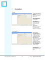
1
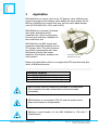
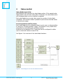
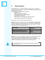
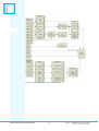
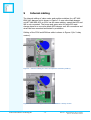
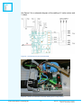
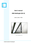
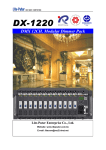
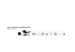
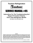
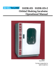
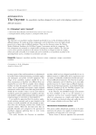
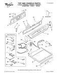
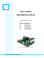
User’s manual
KNX MultiVent (MV-K)
Article number: 5400x
Suitable for the following YIT damper valve types:
Article number Valve description
0504
KT-VAV-KNX-40%-Basic
0505
KT-VAV-KNX-40%-1x16A
0506
KT-VAV-KNX-40%-2x16A
0507
KT-VAV-KNX-60%-Basic
0508
KT-VAV-KNX-60%-1x16A
0509
KT-VAV-KNX-60%-2x16A
0510
KT-VAV-KNX-2x40%-Basic
0511
KT-VAV-KNX-2x40%-1x16A
0512
KT-VAV-KNX-2x40%-2x16A
Picture: Art. no. 54002 - KNX MultiVent with 1 relay
function Innovation & Technology AS
Table of contents:
1
Application __________________________________________________3
2
Valve control ________________________________________________4
3
Relay functions _____________________________________________5
4
Programming and test ______________________________________7
4.1
Installation procedure _________________________________________ 7
5
Internal cabling _____________________________________________8
6
List of objects ______________________________________________10
7
Parameters ________________________________________________13
8
Technical data _____________________________________________16
function Innovation & Technology AS
-2-
Manual – KNX MultiVent Art.no 5400x
Doc.no. D-TS-MV-K-005-A
1
Application
KNX MultiVent is a control card for the YIT damper valve. MultiVent can
control and supervise the damper valve blades and report status via the
KNX bus. MultiVent can control both one- and two valve blade damper
units (KT-VAV-KNX-40%, 60%, and 2x40%)
KNX MultiVent is mounted, furnished
with cables and tested at the
production site. Quick connect plugs
ensures quick and easy installation at
the construction site.
KNX MultiVent has KNX objects and
parameters especially designed for the
YIT damper valve. The valve functions
can directly communicate with other
KNX based products like motion
detectors, thermostats, actuators and
other sensors.
YIT Damper unit with KNX
MultiVent with 1 relay
Relays and valve blades will be un-changed after ETS download and after
return of KNX/mains power.
MultiVent versions:
Art.nr. 54001: KNX MultiVent basic
Art.nr. 54002: KNX MultiVent with 1 relay
Art.nr. 54003: KNX MultiVent with 2 relays
KNX MultiVent must be installed as described in this document.
Note especially the load characteristics and circuit breaker
information.
KNX MultiVent is connected to 230V AC and the printed circuit
board must always be encapsulated.
Maximum circuit breaker for the KNX MultiVent is 16A with Ccharacteristics.
function Innovation & Technology AS
-3-
Manual – KNX MultiVent Art.no 5400x
Doc.no. D-TS-MV-K-005-A
2
Valve control
Valve blade supervision
KNX MultiVent will supervise the valve blade position. If the wanted valve
blade position has not been reach after 40 seconds, the valve blade motor
will be stopped and an error condition is reported.
Each valve blade has a counter that counts the number of valve blade
operations. This function makes it possible to plan service intervals based
on actual valve usage.
Forced operation and Fire-mode
Each valve blade can be configured either to go to open or closed position
by using the “Forced operation” object. This function is very useful when
commissioning and testing the ventilation system.
MultiVent has a dedicated ”Fire” object that can be configured to either
open or close both valves in case of fire.
See Figure 1 for overview of the valve blade functions
Figure 1 – Block diagram over the valve blade functions
function Innovation & Technology AS
-4-
Manual – KNX MultiVent Art.no 5400x
Doc.no. D-TS-MV-K-005-A
3
Relay functions
KNX MultiVent (art.nr. 54002 and 54003) includes one or two general
purpose relays. The relay can control fixed installations like light, electrical
heaters and heat cables.
These functions are available for the relays:
On/Off control
On/Off control with time delay
Staircase function with a disable object
Logical AND or OR function
Force object for either forcing the relay ON or OFF
Heat/Cooling control ON/OFF or PWM control
See Figure 2 for an overview of the relay functions
Note: The relay type is Grüner 707L and is designed for capacitive loads
with large inrush currents like lamp loads. The number of operations for
the relay is dependent upon the type of load and the current. The table
below shows a list of the maximum load.
Type of load
Flourecent light (70µF)
Transformer for halogen light bulbs
Electrical heat cables, electrical heaters
Maximum inrush current
Maximum load
(230V AC)
650W
500VA
1250W
260A i 250 µS
Note: The relay gives an audible sound when the relay changes position.
This sound can cause irritation especially if the relay is used for
heating/cooling control with PWM. Low time period for PWM control will
result in more audible sound and lower life time for the relay.
The number of light fixtures connected to the relay is limited by
the inrush current.
function Innovation & Technology AS
-5-
Manual – KNX MultiVent Art.no 5400x
Doc.no. D-TS-MV-K-005-A
Figure 2 – Block diagram for the relay functions
function Innovation & Technology AS
-6-
Manual – KNX MultiVent Art.no 5400x
Doc.no. D-TS-MV-K-005-A
4
Programming and test
KNX MultiVent has 2 buttons and a LED that are accessible from the side
of the damper valve. The LED can indicate two error conditions by blinking
the LED. The LED will blink 5 times per second if the desired valve blade
position was not reached. This failure situation could be caused by faulty
motor or micro switches, cable- or mechanical malfunction. The LED will
blink once per second if the KNX MultiVent is un-programmed.
The button next to the LED is the KNX Learn
mode button. The LED will be lit permanently
if the learn mode button is pressed. The LED
will start to blink once per second when the
KNX application is being downloaded. The
blinking stops when the download is complete.
LED
Learn mode
button
Test button
The button furthest away from the LED is the test button for checking
proper operation of valve blades and relays. If the button is pressed once
then valve blade 1 will change position. If the button is pressed again
within one minute, valve blade 2 will change position. If the button is for
more than 5 seconds, then relay 1 will change position. If it is pressed for
more than 5 seconds again, relay 2 will change position.
4.1 Installation procedure
1.
2.
3.
4.
5.
6.
7.
8.
Make sure covers and screws are securely fastened
Mount the damper valve on to the ventilation duct.
Connect the KNX cable to the KNX bus (wago quick connect).
Connect the fixed 230V AC load to the Wago chassis plug(s) for 1.
relay or 2. relay version.
Connect the mains cable to 230V (Wago quick connect)
Press the test button once for a one valve blade damper unit or
twice for two valve blade damper unit, check that the valve blades
change position. The relay(s) can be checked by holding the test
button for more than 5 seconds.
KNX MultiVent enters KNX learn mode by pressing the learn mode
button (the button next to the LED).
Download via ETS
function Innovation & Technology AS
-7-
Manual – KNX MultiVent Art.no 5400x
Doc.no. D-TS-MV-K-005-A
5
Internal cabling
The internal cabling of valve motor and position switches for a KT-VAVKNX-2x40 damper unit is shown in Figure 3. A one valve blade damper
unit KT-VAV-KNX-40% or 60% has the same cabling, except that W3 and
W6 is not connected. The brown and green wire for cable W2 must
change place for a one valve blade 60% damper unit. All connections and
wires has been mounted and tested in production.
Cabling of the 230V and KNX bus cable is shown in Figure 4 (for 2.relay
version).
Figure 3 – Internal cabling for motor and position switches (2x40%)
Figure 4 - Internal cabling of 230V mains and KNX for 2. Relay version
function Innovation & Technology AS
-8-
Manual – KNX MultiVent Art.no 5400x
Doc.no. D-TS-MV-K-005-A
See Figure 5 for a schematic diagram of the cabling of 2 valve motors and
2 relays.
Figure 5 - Connections for the controller PCB
Figure 6 – Picture of controller card with cabling for a 1.relay version
function Innovation & Technology AS
-9-
Manual – KNX MultiVent Art.no 5400x
Doc.no. D-TS-MV-K-005-A
6
List of objects
Tabell 1 – General objects
ID
Name
OBJ 000
General:
Self test status
OBJ 001
General:
Fire operation
Description
This object will report self test result and
alive status with a "0" if everything is ok. If
it sends "1" the self test has failed and the
red LED will flash 5 times per second. The
status will be re-set if a new command is
executed successfully.
Fire operation has the highest priority and
will either open or close the valve blades
based on the parameter ”Fire operation”.
Tabell 2 – Objects for valve blade 1
ID
Name
Description
OBJ 002
Valve 1:
The switch object for the valve blade. The
Switch
parameter ”Valve Control” must be set to
”Switch”
Data type
1 bit
1.001
Flag: C R - T
1 bit,1.001
Flag: C - W -
Data type
1 bit
1.001
Flag: C - W -
0=valve closed, 1=valve open
OBJ 002
Valve 1:
Value
OBJ 003
Valve 1:
Force open
OBJ 004
Valve 1:
Force close
OBJ 005
Valve 1:
Status
OBJ 006
Valve 1:
Cycle counter
function Innovation & Technology AS
The object for continuous control (0-100%)
of the valve. The parameter ”Valve Control”
must be set to ”Continuous” and appropriate
limits specified for the parameters ”Open
valve on value higher than (%)” and ”Close
valve on value or lower than (%)”
The valve blade will be forced open by
setting this object high. The priority for
operating the valve is either 2nd or 3rd
depending on parameter ”Forced Priority”.
The valve blade will be forced close by
setting this object high. The priority for
operating the valve is either 2nd or 3rd
depending on parameter ”Forced Priority”.
The object will hold the current status (open
or closed) for the valve blade (0=valve
closed, 1=valve open)
Counts the number of operations for the
valve blade (open and close). This value is
store permanent in EEPROM, and can only
be re-set with a new value from the bus.
ETS download will not overwrite this counter.
- 10 -
1 byte
5.001
Flag: C - W -
1 bit
1.001
Flag: C - W 1 bit
1.001
Flag: C - W 1 bit
1.001
Flag: C R - T
4 byte
12.001
Flag: C R W -
Manual – KNX MultiVent Art.no 5400x
Doc.no. D-TS-MV-K-005-A
Tabell 3 – Objects for valve blade 2
ID
Name
Description
OBJ 007
Valve 2:
The switch object for the valve blade. The
Switch
parameter ”Valve Control” must be set to
”Switch”
Data type
1 bit
1.001
Flag: C - W -
0=valve closed, 1=valve open
OBJ 007
Valve 2:
Value
OBJ 008
Valve 2:
Force open
OBJ 009
Valve 2:
Force close
OBJ 010
Valve 2:
Status
OBJ 011
Valve 2:
Cycle counter
The object for continuous control (0-100%)
of the valve. The parameter ”Valve Control”
must be set to ”Continuous” and appropriate
limits specified for the parameters ”Open
valve on value higher than (%)” and ”Close
valve on value or lower than (%)”
The valve blade will be forced open by
setting this object high. The priority for
operating the valve is either 2nd or 3rd
depending on parameter ”Forced Priority”.
The valve blade will be forced close by
setting this object high. The priority for
operating the valve is either 2nd or 3rd
depending on parameter ”Forced Priority”.
The object will hold the current status (open
or closed) for the valve blade (0=valve
closed, 1=valve open)
Counts the number of operations for the
valve blade (open and close). This value is
store permanent in eprom, and can only be
re-set with a new value from the bus.
ETS download will not overwrite this counter.
Tabell 4 – Objects for relay 1 (Art.nr 54002 and 54003)
ID
Name
Description
OBJ 012
Relay 1:
The switch object to open or close the relay.
The object works for switch actuator, delay
Switch
OBJ 012
Relay 1:
Switch
heating/cooling
OBJ 012
Relay 1:
Continuous
heating/cooling
OBJ 013
Relay 1:
Force operation
OBJ 014
Relay 1:
Disable delay
function
Relay 1:
Disable staircase
function
Relay 1:
Change Duration
OBJ 014
OBJ 015
function Innovation & Technology AS
function and staircase function (1=closed,
0=open).
The object works as an ON/OFF control of
the heating/cooling system. The object is
enabled by choosing "Switch 1bit" for the
"Type of telegram for control" parameter.
The object works as continuous (0-100%)
control of the heating/cooling system. The
object is enabled by choosing "Continuous
1byte" for the "Type of telegram for control"
parameter.
The relay will be forced either ON or OFF
(set by parameter) if this object is set high.
The force operation has the highest priority
Switch off the delay timer function. The relay
will switch momentarily if this object is set
high.
Switch off the staircase timer function. The
relay will switch momentarily if this object is
set high.
Change the timer value in seconds for the
Staircase function. The value is stored until
next ETS download.
NOTE: the time value is stored permanently
in EEPROM, frequent delay changes could
destroy the EEPROM.
- 11 -
1 byte
5.001
Flag: C - W -
1 bit
1.001
Flag: C - W 1 bit
1.001
Flag: C - W 1 bit
1.001
Flag: C R - T
4 byte
12.001
Flag: C R W -
Data type
1 bit
1.001
Flag: C - W 1 bit
1.001
Flag: C - W 1 byte
5.001
Flag: C - W -
1 bit
1.001
Flag: C
1 bit
1.001
Flag: C
1 bit
1.001
Flag: C
2 byte
8.001
Flag: C
-W-
-W-
-W-
RW-
Manual – KNX MultiVent Art.no 5400x
Doc.no. D-TS-MV-K-005-A
Tabell 4 – Continue
OBJ 016
Relay 1:
Logic AND
OBJ 016
Relay 1:
Logic OR
OBJ 017
Relay 1:
Status switch
The object works as a AND gate for the relay
output regardless of which function is
enabled. Forced operation will override the
AND gate. The AND gate is enabled by the
parameter ”Logic”. This object has the initial
value of “1” after power-on.
The object works as an OR gate for the relay
output regardless of which function is
enabled. Forced operation will override the
OR gate. The OR gate is enabled by the
parameter ”Logic”. This object has the initial
value of “0” after power-on.
Holds the status information about the relay
output (1=relay closed, 0=relay open)
Tabell 5 – Objects for relay 2 (Art.nr 54003)
ID
Navn
Beskrivelse
OBJ 018
Relay 2:
The switch object to open or close the relay.
The object works for switch actuator, delay
Switch
OBJ 018
Relay 2:
Switch
heating/cooling
OBJ 018
Relay 2:
Continuous
heating/cooling
OBJ 019
Relay 2:
Force operation
OBJ 020
Relay 2:
Disable delay
function
Relay 2:
Disable staircase
function
Relay 2:
Change Duration
OBJ 020
OBJ 021
OBJ 022
Relay 2:
Logic AND
OBJ 022
Relay 2:
Logic OR
OBJ 023
Relay 2:
Status switch
function Innovation & Technology AS
function and staircase function (1=closed,
0=open).
The object works as an ON/OFF control of
the heating/cooling system. The object is
enabled by choosing "Switch 1bit" for the
"Type of telegram for control" parameter.
The object works as continuous (0-100%)
control of the heating/cooling system. The
object is enabled by choosing "Continuous
1byte" for the "Type of telegram for control"
parameter.
The relay will be forced either ON or OFF
(set by parameter) if this object is set high.
The force operation has the highest priority
Switch off the delay timer function. The relay
will switch momentarily if this object is set
high.
Switch off the staircase timer function. The
relay will switch momentarily if this object is
set high.
Change the timer value in seconds for the
Staircase function. The value is stored until
next ETS download.
NOTE: the time value is stored permanently
in EEPROM, frequent delay changes could
destroy the EEPROM.
The object works as a AND gate for the relay
output regardless of which function is
enabled. Forced operation will override the
AND gate. The AND gate is enabled by the
parameter ”Logic”. This object has the initial
value of “1” after power-on.
The object works as an OR gate for the relay
output regardless of which function is
enabled. Forced operation will override the
OR gate. The OR gate is enabled by the
parameter ”Logic”. This object has the initial
value of “0” after power-on.
Holds the status information about the relay
output (1=relay closed, 0=relay open)
- 12 -
1 bit
1.001
Flag: C - W -
1 bit
1.001
Flag: C - W -
1 bit
1.001
Flag: C R - T
Data type
1 bit
1.001
Flag: C - W 1 bit
1.001
Flag: C - W 1 byte
5.001
Flag: C - W -
1 bit
1.001
Flag: C
1 bit
1.001
Flag: C
1 bit
1.001
Flag: C
2 byte
8.001
Flag: C
-W-
-W-
-W-
RW-
1 bit
1.001
C-W-
1 bit
1.001
C-W-
1 bit
1.001
Flag: C R - T
Manual – KNX MultiVent Art.no 5400x
Doc.no. D-TS-MV-K-005-A
7
Parameters
General
”Cyclic sending status of
device”:
Choose the number of hours
between cyclic sending of
status [0..24].
”Valve configuration”:
Choose to control one or
two valve blades.
”Fire operation”:
Choose either to open or
close the valve blades
(works for both valve
blades)
”Relay count”:
Choose 0, 1 og 2 relè. The
choices will be limited
depending on the hardware.
Valve blade 1 & 2
”Valve control”:
Choose either ”Switch” to
get a 1. bit object or
”Continuous control” to get
a 1.byte control object.
”Open valve on value
higher than (%)”:
Value where the valve blade
will open. Only visible for
”Continous control”.
”Close valve on value
lower than (%)”: Value
where the valve blade will
close. Only visible for
”Continous control”.
”Forced priority”:
Choose priority order for the
force open and force close
objects.
function Innovation & Technology AS
- 13 -
Manual – KNX MultiVent Art.no 5400x
Doc.no. D-TS-MV-K-005-A
Relay - Switching actuator
”Function”:
Choose ”Switching actuator”
or ”Heating/Cooling
actuator” function for the
relay.
”Additional function”:
Choose ”Disable”, ”On/off
delay” or ”Staircase function”
for the switching actuator.
”Logic”:
Activate object for logical
function ”AND” or ”OR”.
”Forced operation”:
Choose if the relay should
turn ON or OFF when the
”Force operation” object is
set.
”Staircase function”
Specify the number of
minutes the ”Staircase
function” is on [0..255]. The
staircase function is disabled
by choosing 0.
”Possibility to switch off
the relay from the bus”:
Specify if the relay can be
turned OFF when the
staircase function is active.
function Innovation & Technology AS
- 14 -
Manual – KNX MultiVent Art.no 5400x
Doc.no. D-TS-MV-K-005-A
Relay - Heating/Cooling actuator
”Valve actuator type”:
Specify if the valve is
normaly closed (no heat
when the relay is off), or
normaly open (heat when
the relay is off).
”Type of telegram for
control”:
Choose ON/OFF control
(Switch 1. bit object) or
PWM control (Contionous 1.
byte object) of the heating
or cooling system.
”Automatic vale purge”:
Specify the number of days
between valve purge. The
valve purge will last for 5
minutes.
”Continuous (1 byte)”
Heating/cooling actuator
PWM cycle time (min):
Specify the time period for
the PWM control in minutes.
function Innovation & Technology AS
- 15 -
Manual – KNX MultiVent Art.no 5400x
Doc.no. D-TS-MV-K-005-A
8
Technical data
Power
-
Operating voltage
Current consumption KNX
230V AC
21-30 V DC, made available by the bus
Normally 7mA, Peak 18mA
12VA when both valves are operated
Output relay
-
Number potential free contacts
Un rated voltage
In rated current (one relay/two relays))
Power loss at max. load
Mechanical operations
2 (in group for YIT Valve)
230 VAC (50 Hz)
10A/16A
4W
100.000
Output relay switching
power
-
Fluorecent light (70µF)
Incandecent light bulbs
Transformer for halogen bulbs
Heat cables, heaters etc.
Maximum inrush current
650W
1200W
500VA
1250W
260A / 250 µS
Output motor valves
-
Number
UN rated voltage
IN rated current each output
2
230 VAC (50 Hz)
0,3A
Inputs
-
Valve blade position switches
Polling voltage UN
Sensing current IN
Permitted cable lengths
4
3.7V
0.4mA
1m
Connections
-
KNX
230V
via Molex terminal, without screws
via Molex terminal, without screws
EIB / KNX voltage
-
SELV 24 V DC
(safety extra low voltage)
Temperature range
-
Operation
Storage
Transport
– 5 °C ... + 45 °C
– 25 °C ... + 55 °C
– 25 °C ... + 70 °C
Design
Approvals
CE mark
-
Dimensions (H x W x D)
EIB / KNX EN 50 090-2-2
In accordance with the EMC guideline
and low voltage guideline.
31mm x 76mm x 62mm
Certification
Data subject to change without notice
Producer:
Distributor:
function Innovation & Technology AS
fabrikkgaten 5 | N-5059 Bergen | Norway
function Product & Solution AS
fabrikkgaten 5 | N-5059 Bergen | Norway
Tel: +47 55 38 50 80
Email: [email protected]
WEB: www.function.no
function Innovation & Technology AS
- 16 -
Manual – KNX MultiVent Art.no 5400x
Doc.no. D-TS-MV-K-005-A