1
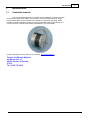
3 axis controller
User manual
© 2002 Twintec
Twintec controller user manual
3 axis controller user manual
© 2002 Twintec
All rights reserved. No parts of this work can be reproduced in any form without a written permission of the author.
The products to who references are made in this manual can be trademark of the respective proprietary. The author
assume no responsability for errors or omissions, or for damage caused by the usage of the informations contained in
this document and by the usage of the products to who it refer. In no case the author can be responsible of damage
caused directly or indirectly by this document.
Printed: novembre 2002 at Gravina di Catania Italy
Published by:
Twintec
Address:
Via Monti Arsi, 13
95030 Gravina di Catania IT
Tel. 39 95 7253415
Author:
Michele Ribaudo
Web site:
http://www.twintec.it
e-mail:
[email protected]
I
3 axis controller user manual
Contents
Introduction
0
2
I Introduction
1 Controller...................................................................................................................................
manual
2
3
II Hardware
1 General description
................................................................................................................................... 3
2 Connections
...................................................................................................................................
description
5
3 Electrical characteristics
................................................................................................................................... 7
4 Status indicators
................................................................................................................................... 7
5 Accessory................................................................................................................................... 7
Controller .........................................................................................................................................................
connector
7
8
III Software
1 Command...................................................................................................................................
syntax
8
2 List of commands
................................................................................................................................... 8
Move
......................................................................................................................................................... 8
Move contour
......................................................................................................................................................... 8
Set the contour
.........................................................................................................................................................
angle
9
Set the speed
......................................................................................................................................................... 9
Set the acceleration
......................................................................................................................................................... 9
Activate output
......................................................................................................................................................... 10
Wait an input
......................................................................................................................................................... 10
Wait a time
......................................................................................................................................................... 10
Execute home
......................................................................................................................................................... 10
Set the position
......................................................................................................................................................... 11
Configure......................................................................................................................................................... 11
12
IV Operation principles
1 General Principles
................................................................................................................................... 12
2 Communication
................................................................................................................................... 13
3 Speed and
...................................................................................................................................
acceleration
13
4 Vector's execution
................................................................................................................................... 15
Index
16
© 2002 Twintec
Introduction
1
Introduction
1.1
Controller manual
This manual, destinated to the controller users is divided in 4 sections to make
more easy the arguments reading. We choose to not limit the manual to the simple
thecnical description of the controller but to explain any argument, providing, where
possible, examples and pictures than can give to the reader further informations for a
correct use of the controller and a better understanding of it functionality.
Further informations can be found on our web site: http://www.twintec.it
Twintec di Ribaudo Michele
Via Monti Arsi, 13
95030 Gravina di Catania
ITALY
Tel. 39 95 7253415
© 2002 Twintec
2
3
3 axis controller user manual
2
Hardware
2.1
General description
3 axis controller
·
·
·
·
·
·
·
·
·
·
·
·
·
·
·
·
Eurocard board 100X160 mm. connector DIN 96 poles.
LED indicators for power, execution and error.
Power supply 5V 200 mA.
3 AXIS interpolated.
2 serial port: Rs232 19200-38400 BPS. e RS 485 19200 a 38400.
Communication protocol: RS232 Hardware Handshake via CTS-RTS..
8 user input CMOS 5V.
8 user output OPEN COLLECTOR max 100 mA.
Inputs for HOME and LIMIT for all axis.
STOP input.
STOP with deceleration and acceleration at restart.
CONTOURING with adjustable angle.
Battery for data retention (6 month).
Configuration buffer for startup.
Input and output commands.
Timing commands.
Drawing of the controller.
© 2002 Twintec
Hardware
Led indicators descripition:
· PWR=POWER LED
· ERR=ERROR AND STOP LED
· STAT=STATUS LED
© 2002 Twintec
4
5
3 axis controller user manual
2.2
Connections description
In the following table the name of the signals.
VCC
5V supply.
GND
Ground.
PULSE0
PULSE1
PULSE2
DIR0
DIR1
DIR2
Step output X
Step output Y
Step output Z
Direction output X
Direction output Y
Direction output Z
UI0.. UI7
UO0..UO7
UO Com.
User inputs.
User outputs.
Common snubber for
outputs
HOME0
HOME1
HOME2
LIM0
LIM1
LIM2
RXD
TXD
CTS
RTS
ANA1
ANA2
Home input X.
Home inputY.
Home input Z.
Limit Input X.
Limit input Y.
Limit input Z.
Data input rs232
Data output rs232
Clear to send rs232
Request to send 232
Analogic input 0-5V
Analogic input 0-5V
PULSE3
DIR3
Step output (optional).
Direction output (optional).
The following table show the drawing of the connector front view and the coresponding pin
and signal.
© 2002 Twintec
Hardware
a32
a31
a30
a29
a28
a27
a26
a25
a24
a23
a22
a21
a20
a19
a18
a17
a16
a15
a14
a13
a12
a11
a10
a9
a8
a7
a6
a5
a4
a3
a2
a1
b32
b31
GND
b30
b29
b28
b27
LIM0
b26
STOP
b25
LIM2
b24
b23
CTS
b22
TXD
b21
RXD
b20
UI7
b19
UI2
b18
b17
b16
Dir 0
b15
Pulse0
b14
b13
GND
b12
GND
b11
b10
b9
b8
b7
UO2
b6
UO5
b5
UO Com. b4
GND
b3
VCC
b2
VCC
b1
Here the serial connector.
Connettore DB9 RS 232
ANA 1
LIM 1
HOME1
RTS
UI1
UI5
GND
GND
Dir 1
Pulse1
GND
UO1
UO4
UO7
GND
VCC
VCC
ANA2
HOME0
HOME2
UI0
UI6
UI3
UI4
GND
Dir 2
Pulse2
GND
Pulse3
Dir3
UO0
UO3
UO6
GND
VCC
VCC
Data receive (PC)
Data transmit (PC)
Shortened (DTR DSR)
Ground
Clear to send (PC)
Request to send (PC)
Related signals
1 GROUND
2 BUS A
3 BUS B
© 2002 Twintec
GND
Related signals
2 RXD
3 TXD
4-----6
5 GND
7 CTS
8 RTS
and the RS 485 connector
RS 485 connector
GND
c32
c31
c30
c29
c28
c27
c26
c25
c24
c23
c22
c21
c20
c19
c18
c17
c16
c15
c14
c13
c12
c11
c10
c9
c8
c7
c6
c5
c4
c3
c2
c1
6
7
3 axis controller user manual
2.3
Electrical characteristics
Power supply: 5V 200 mA max.
Input home and limits: Normaly closed CMOS 5 V with pull-up da 10 KOhm.
User input:
pull-up 10KOhm.
User output: Open collector max 100 mA.
Step and dir output: Open collector without pull-up.
Ouput IC: ULN2803;
Input IC: 74HC244;
2.4
Status indicators
The LED indicators are three:
1.
2.
3.
GREEN LED: indicate the power is on.
RED LED: Have three states:
·
OFF: nessun errore.
·
FLASHING: The STOP is Pressed.
·
ON: A limit have benn reached.
YELLOW LED: have two states:
· 1 sec. Flashing: The controller is in the stand-by state.
· 1/2 sec. flashing: The controller is executing commands.
2.5
Accessory
2.5.1
Controller connector
This board allow the connection of the controller with detachable connectors. It comprise a
5V stabilized power so the input can be 9~15 V cc.. On the back there is a LED that
indicate the power presence and is possible to add a DB9 connector whenever the one on
the controller will result in an unfavorable position.
Power supply 9~15 V CC. 200 mA.
© 2002 Twintec
Hardware
Nota: Not all the signals are disponible on that connector
Signals present:
UO common
UO 0..3
UI 0..3
PULSE 0,1,2
DIR 0,1,2
LIM 0,1,2
STOP
HOME 0,1,2
GND
VCC
ANA 1,2
3
Software
3.1
Command syntax
All commands are of two characters and a list of parameters delimited by a comma,
the command terminator is the semi-colon ";".
MC100,100,100;
Spaced are discarded by the controller.
MC 100, 100, 100;
The interpreter is case insensitive;
mc 100,100,100;
Follow the description of the commands, the syntax, limits and error condition.
3.2
List of commands
3.2.1
Move
Syntax:
MV X,Y,Z;
Purpose: Move the axis at the specified position with acceleration and deceleration.
Parameters: X,Y and Z.
Example: MV 100, 100, 400;
Limits: 8388608÷ -8388608
Errors: Missing parrameter, parameter out of limit.
Note: The position are in step and are absolute.
3.2.2
Move contour
Syntax:
MC X,Y,Z;
Purpose: Move the axis at the specified position inside a path. If the angle between
the vector and the previous one is greater than the angle of contour the controller
will decelerate if in move and then accelerate to begin this position motion
© 2002 Twintec
8
9
3 axis controller user manual
(see the paragraph for the vector execution).
Parameters: X,Y e Z.
Example: MC 100, 100, 400;
Limits: 8388608÷ -8388608
Errors: Missing parrameter, parameter out of limit.
Note: The position are in step and are absolute.
3.2.3
Set the contour angle
Syntax:
SI A;
Purpose: Set the contour angle (see the paragraph for the vector execution).
Parameters: A. Contour angle in degree;
Example: SI 25;
Limits: 0-360;
Errors: Missing parrameter, parameter out of limit.
3.2.4
Set the speed
Syntax:
SV V;
Purpose: Set the speed for the next vectors (see paragraph Speed and acceleration).
Parameters: V. Speed in cm/s.
Example: SV 2.5;
Limits: 1.2-20;
Errors: Missing parrameter, parameter out of limit.
3.2.5
Set the acceleration
Syntax:
SA A;
Purpose: Set the acceleration in cm/s² (see paragraph Speed and acceleration).
Parameters: A. acceleration in cm/s².
Example: SA 5.5;
Limits: 1.2-40;
Errors: Missing parrameter, parameter out of limit.
© 2002 Twintec
Software
3.2.6
Activate output
Syntax:
EO bit,value;
Purpose: Set the user output at the specified value.
Parameters: bit: number 0..7, value 0-1.
Example: EO 7,1;
Limits: 0..7, 0-1;
Errors: Missing parrameter, parameter out of limit.
3.2.7
Wait an input
Syntax:
WI bit,valore;
Purpose: Wait a specified value on a user input bit.
Parameters: bit: number 0..7, value 0-1.
Example: WI 7,1;
Limits: 0..7, 0-1;
Errors: Missing parrameter, parameter out of limit.
3.2.8
Wait a time
Syntax:
EW tempo;
Purpose: Wait for the specified time in ms.
Parameters: time in ms.
Example: EW 1000; wait a second
Limits: 10-65536;
Errors: Missing parrameter, parameter out of limit.
3.2.9
Execute home
Syntax:
EH x,y,z;
Purpose: Bring the axis at the home position seeking the specified switch. At the end of the
command the internal position is 0,0,0.
Parameters: x,y,z. 0 mean no seek 1 mean seek the switch.
Example: EH 1,1,0; Seek the home switch for the x and y axis.
Limits: 0-1;
© 2002 Twintec
10
11
3 axis controller user manual
Errors: Missing parrameter, parameter out of limit.
3.2.10 Set the position
Syntax:
SP x,y,z;
Purpose: Set the logical position without making any move.
Parameters: x,y,z.
Example: SP 1000,1000,0;
Limits:
Errors: Missing parrameter, parameter out of limit, command received in
excecution phase.
Note: This command have to be executed carefully, the command will be refused if
the controller is excecuting vectors.
3.2.11 Configure
Syntax:
CF tipo, p1[, p2][, p2];
These commands are for configuration that are retained even when the controller
power is not present.
Configure HOME:
Syntax:
CF 1,x,y,z;
Purpose: Set how the controller search the Home switch at the reset.
Parameters: x,y,z.
Default value: 0,0,0;
Example: CF1,0,0;
Limits: 0-1;
Note: This command have no immediate effect, but it configure the controller to
seek or not the home switch at the reset. If we send the command CF 1,1,1,0; at
the next reset the controller will seek the switch that are set to one.
Configure Axis resolution:
Syntax:
CF 2,x,y,z;
Purpose: Set the axis resolution for the three axis in step/mm.
Parameters: x,y,z.
Default value: 40,40,40;
Example: CF2,40,40,80;
© 2002 Twintec
Software
Limits: 1-400;
Note: this command have effect on the speed calculation.
Configure Home Speed:
Syntax:
CF 3,f;
Purpose: Set the home frequency.
Parameters: f: frequency.
Valore predefinito: 1000;
Example: CF2500;
Limits: 100-10000;
4
Operation principles
This chapter describe the operation principle of a positioning system.
4.1
General Principles
Block diagram of a positioning system:
© 2002 Twintec
12
13
3 axis controller user manual
The controller is the headt of a positioning system. It perform the following tasks:
· Generate the direction signals and step frequencies to the drivers to move the motors at
the desired position.
· Activate the outputs.
· Wait a status at an input.
· Perform the timing between two command.
· Transmit informations about the position and the status.
· Acquire the Stop status.
· Acquire the Limits status.
· Seek the Home switch to put the axis in this position.
The actions above mentioned can be performed by comunicating, trhough the serial PC
line, with defined commands than will be executed by the controller in the sequence that
are been transmitted. In the controller there is a receive buffer that allow the same to
execute work of hours without interruptions. The communication handshake is managed
by the CTS and RTS control signals.
4.2
Communication
The communication with the controller is established with RS232: the line parameters are:
Bit:8
Stop bit: 1
Parity: None
Baud rate: 19200 bps.
The cable to use is a simple direct MF DB9.
The flow control signals are RTS and CTS. Note: in absence of those signals an
overwriting of the buffer can occur with severe consequence for the correct
excecution.
The RS 485 is optional and is reserved for future or custom usages.
4.3
Speed and acceleration
The speed, in a system composed by three axis is done with the following
formula:
here V is the speed and vx,vy, vx are the component speeds.The
controller calculate the component speeds for any axis to make the final desired speed that can
be set with the SVv; command where v is the speed in cm/s
The acceleration of a system is the variation of the velocity with the time, this parameter is set in
cm/s² in the controller.
The controller have two command for the setting of these parameters, read the
© 2002 Twintec
Operation principles
paragraphs set the speed e set the acceleration for a detailed esplanation of these commands.
When the controller have to move at a defined position it start to send pulse with an increasing
frequency until it reach the final speed and continue with this speed until it reach the position
calculated for the deceleration. The following diagram show how the curve of the velocity for a
single vector assume a trapeziodal form. The vertical axis represent the speed and the orizontal
the time.
If the length of the vector is too small to reach the final velocity the form of the curve is a
triangle.
2
1,8
1,6
1,4
1,2
1
0,8
0,6
0,4
0,2
0
0
0,1
0,2
0,3
0,4
The correct setting of these two parameters (speed and acceleration) allow to reache optimal
performances relating the speed and the positioning accuracy. It is necessary to consider the
kind of work to execute before set these two parameters. The step loss can be a consequence
of the incorrect setting of a speed or an acceleration. It is a good practice to refer with the
caracteristics of the motor to find the correct values.
© 2002 Twintec
14
15
3 axis controller user manual
4.4
Vector's execution
To explain how the controller perform the axis positioning it is necessary to introduce the
concept of a vector and the path.
In the following diagram we can see a path composed of 4 vectors. To make that path we
have to send to the controller 4 position command. We suppose that the controller start from
the position 0.0.0 and all vectors are on the same level so the Z value is 0.
List of commands:
Position diagram
MC20,20,0;
MC40,30,0;
MC60,90,0;
MC80,20,0;
If the contouring angle is set to 23° (default value) the execution of that path is done with 3
accelerations and 3 decelerations. This because the angle between the first and the second
vector is less than 23° while the angle between the second and the third vector and between
the third and the fourth is greater than 23°.
The sequence will be the following:
1. accelerate from the 0,0,0 position until reach the final speed.
2. reach the position 20,20,0 and it continue in the direction of the 40,30,0 position
3. decelerate until it reach teh 40,30,0 position.
4. accelerate in the direction of the 60,90,0 position
5. decelerate until it reache the 60,90,0 position
6. accelerate in the direction of the 80,20,0 position
7. decelerate until it reach the final position 80,20,0
f we want to execute the move with an acceleration and a deceleration every vector
independently of the angle we have to use the MV command instead of the MC one.
© 2002 Twintec
Index
Index
-Pposition 11
position set 11
principle 12
- Aacceleration 9
acceleration setting
angle 9
axis resolution 11
-Rred led
9
-Ssignals 5
speed 9
speed and acceleration
speed setting 9
syntax 8
-Ccharacteristics 7
communications 13
configuration 11
configure 11
connection 7
connection description
connections 5
connector 7
contour angle 9
controller signals 5
-E10
-Ggeneral description 3
general principles 12
green led 7
-Hhome
10
-Iindicators 7
input 10
input wait 10
Introduction 2
-Lled
-T5
timing 10
timing wait 10
-Vvectors execution
-Yyellow led
execute home
7
-MMove 8
Move contour
8
-Ooutput 10
output setting
© 2002 Twintec
10
7
7
15
13
16
17
3 axis controller user manual
NOTE
© 2002 Twintec