1
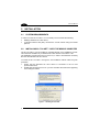
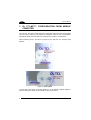
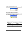
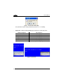
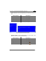
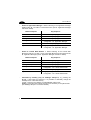
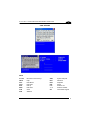
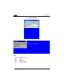
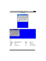
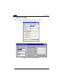
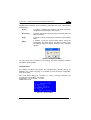
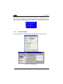
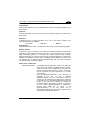
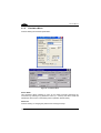
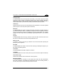
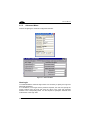
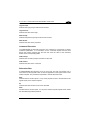
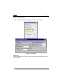
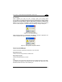
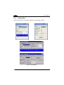
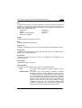
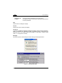
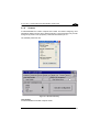
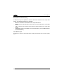
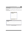
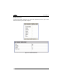
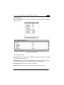
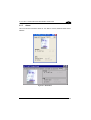
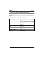
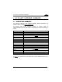
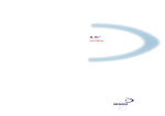
DL TCL-NET™
User’s Manual
DL TCL-NET™
USER'S MANUAL
DATALOGIC S.p.A.
Via Candini 2
40012 - Lippo di Calderara di Reno
Bologna - Italy
DL TCL-NET™
Ed.: 05/2006
This manual refers to DL TCL-NET™ software version 1.2.1.0 or later.
ALL RIGHTS RESERVED
Datalogic reserves the right to make modifications or improvements without prior notification.
Datalogic shall not be liable for technical or editorial errors or omissions contained herein, nor for incidental or
consequential damages resulting from the use of this material.
Product names mentioned herein are for identification purposes only and may be trademarks and or
registered trademarks of their respective companies.
© Datalogic S.p.A. 2003 - 2006
17/05/2006
CONTENTS
1
1.1
GENERAL INFORMATION .......................................................................... 1
DL TCL-NET™.............................................................................................. 1
2
2.1
2.2
2.3
INSTALLATION............................................................................................ 2
System Requirements................................................................................... 2
Installing DL TCL-NET™ onto the Mobile Computer ........................................ 2
Starting DL TCL-NET™ Client ...................................................................... 3
3
3.1
3.1.1
3.1.2
3.1.3
3.1.4
3.1.5
3.1.6
3.1.7
DL TCL-NET™ CONFIGURATION FROM MOBILE COMPUTER .............. 4
Main Setup Menu........................................................................................ 12
Connection Menu........................................................................................ 14
Emulation Menu .......................................................................................... 18
Advanced Menu .......................................................................................... 20
Device Menu ............................................................................................... 22
Display Menu .............................................................................................. 24
Scanner ...................................................................................................... 27
About .......................................................................................................... 33
4
MOBILE COMPUTER ERROR MESSAGES ............................................. 34
5
5.1
DL TCL-NET™ EXTENDED COMMANDS ................................................ 35
Proprietary Commands ............................................................................... 35
A
TERMINAL EMULATION KEYBOARD OVERLAYS ................................. 37
Viper-NET™ Mobile Computer ................................................................... 37
Rhino-NET™ Mobile computer ................................................................... 40
Kyman-NET™ Mobile Computer................................................................. 41
Datalogic Skorpio™ Mobile Computer ........................................................ 47
iii
iv
GENERAL INFORMATION
1
1.1
1
GENERAL INFORMATION
DL TCL-NET™
Datalogic Terminal Emulation Client (DL TCL) for Windows CE .NET is a software
providing VT100, VT220, IBM3270 and IBM5250 Telnet terminal emulation on
Datalogic RF portable mobile computers having a hardware architecture for
Windows CE .NET operating system (Viper-NET™, Rhino-NET™, Datalogic Jet™,
Kyman-NET™ and Datalogic Skorpio™).
If some parameters of the DL TCL-NET™ configuration, defined and downloaded
through the DL Mobile Director™ Local Configurator (see DL Mobile Director™ Local
Configurator Help on Line for details) should be modified, it is possible to define their
new values directly from the mobile computer.
DL TCL-NET™ provides enhanced features for managing the application based on
the Telnet protocol terminal emulation, in particular:
-
Managing the configuration of scanner parameters;
Managing multiple host lists;
Running up to 4 sessions with different hosts and different emulation protocols
simultaneously;
Managing “Out of range” detection;
Advanced barcode filtering, formatting, stripping and replacing functionality;
Selecting several fonts, different font sizes, foreground and background colors;
Mapping the keyboard for all the mobile computers;
Assigning macro function to mobile computer keys;
Managing beeper and backlight;
Logging events;
Automatic login;
Relocating lines to different positions;
Managing different display scrolling modes;
Managing the printer through electrical, IrDA or Bluetooth® interface;
FTP Server embedded.
DL TCL-NET™ satisfies all the connection modes required by your application,
providing both direct connections to the host and through DL Keep Connecting™
gateway software.
1
DL TCL-NET™
2
2
2.1
INSTALLATION
SYSTEM REQUIREMENTS
In order to run the DL TCL-NET™, it is necessary to have at least the following:
• Datalogic Windows CE .NET device;
• a network interface card (NIC) connected to a local network using the TCP/IP
protocol.
2.2
INSTALLING DL TCL-NET™ ONTO THE MOBILE COMPUTER
The DL TCL-NET™ can be installed or upgraded through a PC installation process.
This method is available only for Windows CE .NET devices connected to a PC.
The installation program has to be run on the PC, in order to download the necessary
files onto the Windows CE .NET device.
To install the DL TCL-NET™ through the PC installation method follow the given
procedure:
1. ensure that the Windows CE .NET device is connected to the PC and
synchronized with it;
2. double-click the setup.exe icon on your PC and follow the instructions appearing
in the dialog box below:
Figure 1 – Installing DL TCL-NET
2
INSTALLATION
3.
2
once the installation has been completed, the following message appears:
Figure 2 – Checking your Device Screen
Now, all necessary files are downloaded onto the Windows CE .NET device.
2.3
STARTING DL TCL-NET™ CLIENT
To start DL TCL-NET™ tap the Start button on the screen and select the
DL TCL-NET™ option from the Programs list OR double tap the DL TCL-NET™ icon
available in the Connections folder on the desktop.
OPTION
Figure 3 – Starting DL TCL-NET
3
DL TCL-NET™
3
3
DL TCL-NET™ CONFIGURATION FROM MOBILE
COMPUTER
Once the DL TCL-NET™ application and configuration files have been downloaded
onto the mobile computer, it is possible to change the value for most of the defined
parameters directly from the device by using the DL TCL-NET™ control panel.
When launching the DL TCL-NET™ program for the first time, the opening mask
appears:
Figure 4 – Opening Mask
To enter the control panel, press the [ESC] key on the mobile computer display to
open the dialog box where you are asked to type your password:
4
DL TCL-NET™ CONFIGURATION FROM MOBILE COMPUTER
3
Figure 5 –Password Dialog Box
Once the correct password has been inserted (the default password is ls), it is
possible to enter the DL TCL-NET™ control panel (see par. 3.1).
The password can be modified after entering the main setup menu for the first time.
By pressing the [Enter] key from the opening mask you try the connection with a Host
or Keep Connecting gateway. If no a Host or Keep Connecting gateway is available
for radio communication, the program sends an error message.
Figure 6 - Error Message
Press the [Enter] key or tap OK in the message box to return to the opening mask.
If the connection is successful the user is connected to the Host or Keep Connecting
gateway.
During the connection the following special function keys are available:
-
Exit emulation: by pressing the “Exit Emulation Key” the following dialog box is
displayed allowing to quit the terminal emulation at any time and display the
opening mask:
Mobile Computer
Key Sequence
Rhino-NET™
[F10]
Viper-NET™
[F10]
Datalogic Skorpio™
[F10]
Datalogic Jet™
[F3]
Kyman-NET™
[F10]
5
DL TCL-NET™
3
Figure 7 - Exit Emulation Dialog Box
This procedure requires exiting all sessions (see par. 3.1.1 for details);
-
Input panel: it allows enabling/disabling the Windows CE .NET input panel.
Mobile Computer
Key Sequence
Rhino-NET™
[ALT]+[K]
Viper-NET™
[ALT]+[K]
Datalogic Skorpio™
[ALT]+[K]
Datalogic Jet™
[FUNC]+[UP]
Kyman-NET™
Kyman-NET™ num. model
[ALT]+[K]
[YELLOW]+[UP]
Figure 8 - Input Panel
6
DL TCL-NET™ CONFIGURATION FROM MOBILE COMPUTER
-
3
Enable scroll bar: it allows enabling/disabling the horizontal and vertical scroll
bars.
Mobile Computer
Key Sequence
Rhino-NET™
[ALT] + [S]
Viper-NET™
[ALT] + [S]
Datalogic Skorpio™
Datalogic Jet™
[ALT] + [S]
[FUNC]+[DOWN]
Kyman-NET™
[ALT] + [S]
Kyman-NET™ num. model
[YELLOW]+[DOWN]
Figure 9 - Horizontal and Vertical Scroll Bars
-
Emulation keypad: it allows enabling/disabling the special keypad, which
permits the user to send the emulated function keys.
Mobile Computer
Key Sequence
Rhino-NET™
[ALT] + [F]
Viper-NET™
[ALT] + [F]
Datalogic Skorpio™
[ALT] + [F]
Datalogic Jet™
Kyman-NET™
Kyman-NET™ num- model
Folder key (
)
[ALT] + [F]
Folder key (
)
7
DL TCL-NET™
3
-
Switch to Application Manager: it allows switching to the Application Manager
desktop when DL TCL-NET™ is launched from it (see DL Application Manager
manual for details).
Mobile Computer
Rhino-NET™
[ALT] + [M]
Viper-NET™
[ALT] + [M]
Datalogic Skorpio™
[ALT] + [M]
Datalogic Jet™
Kyman-NET™
Kyman-NET™ num. model
-
[ALT] + [M]
Remapping through DL Mobile Director™ Local
Configurator – DL Application Manager
Key Sequence
Rhino-NET™
[ALT] + [L]
Viper-NET™
[ALT] + [L]
Datalogic Skorpio™
[ALT] + [L]
Datalogic Jet™
Remapping through DL Mobile Director™ Local
Configurator – DL Locked Web Browser
Kyman-NET™
[ALT] + [L]
Kyman-NET™ num. model
8
Remapping through DL Mobile Director™ Local
Configurator – DL Application Manager
Switch to Locked Web Browser: it allows switching to the Locked Web
Browser if both DL TCL-NET™ and Locked Web Browser are launched from the
DL Application Manager (see DL Application Manager manual for details).
Mobile Computer
-
Key Sequence
Remapping through DL Mobile Director™ Local
Configurator – DL Locked Web Browser
YELLOW key modality (only for Datalogic Skorpio™): by pressing the
[BLUE] + [YELLOW] key sequence, it is possible to alternately change the
modality of use of the YELLOW key.
Toggle = press the YELLOW key to enable/disable yellow mode
Modifier = press the YELLOW key each time it is necessary to use yellow mode
(see Datalogic Skorpio™ manual for details).
DL TCL-NET™ CONFIGURATION FROM MOBILE COMPUTER
3
5250 KEYPAD
KEYS
F1..F24
HELP
FLDFLD+
RUP
RDN
CLR
ATN
Ibm 5250 Function Keys
Help
Field Minus
Field Plus
Roll-up
Roll-down
Clear
Attention
SRQ
FEX
DUP
RST
List
1…4
OK
System Request
Field Exit
Duplicate
Reset
Session List
Session Number
Close 5250 Keypad
9
DL TCL-NET™
3
VT 100/220 KEYPAD
KEYS
F1..F20
ESC
List
1…4
OK
10
VT Function Keys
Escape
Session List
Session Number
Close VT Keypad
DL TCL-NET™ CONFIGURATION FROM MOBILE COMPUTER
3
3270 KEYPAD
KEYS
F1..F24
PA1..PA3
CLEAR
ATTN
SREQ
IBM 3270 Function Keys
Program Attention
Clear
Attention
System Request
EOF
RESET
List
1…4
OK
End of Field
Reset
Session List
Session Number
Close 3270 Keypad
11
DL TCL-NET™
3
3.1
MAIN SETUP MENU
The DL TCL-NET™ control panel opening mask appears as follows:
Figure 10 – Control Panel Opening Mask
12
DL TCL-NET™ CONFIGURATION FROM MOBILE COMPUTER
3
All parameters and folders can be selected by using either the stylus or the following
keyboard keys:
-
[Enter]:
if pressed, it validates the selection and allows saving the
configuration when exiting the control panel.
-
Arrow Keys:
if pressed, they allow scrolling all pages horizontally when the
folder is selected.
-
[Tab]:
If pressed, it allows scrolling each parameter of the selected
folder.
-
[ESC]:
if pressed, it exits the Control Panel without saving the
configuration. By exiting the DL TCL-NET™ Control Panel,
the following dialog box appears allowing to exit to Windows
CE NET:
Figure 11 – Exiting DL TCL-NET™
The main setup menu is shared by all Datalogic RF mobile computers. Different
parameters will be signaled.
Text Mode Menu
By pressing the [SHIFT] and [ESC] keys simultaneously ([FUNC] and [0] for
Datalogic Jet™ mobile computer), it is possible to enter the device configuration
menu in text mode.
This menu allows setting DL TCL-NET™ in order to manage extended color
commands for VT emulation. Use options:
2) Emulation -> 2) VT100/200 -> 7) Color
Default value is ON.
Figure 12 – VT Color Option
13
DL TCL-NET™
3
If entering the text mode menu through the ftp password, it is possible to start the
internal TCL FTP Server. Thus, an FTP client can be connected to the TCL FTP
Server through the IP address displayed on the device, as shown in the figure below:
Figure 13 – FTP Server
3.1.1
Connection Menu
It allows configuring the connection between the application and the remote host:
Figure 14 - Connection Menu
14
DL TCL-NET™ CONFIGURATION FROM MOBILE COMPUTER
3
Host Name/IP
It defines the Network name or IP address to be used by the mobile computer for the
first host list.
Host Port
It defines the Telnet TCP/IP port to be used by the mobile computer to connect to the
first host list.
Emulation
It defines the type of Telnet emulation to be run on the mobile computer. The
following selections are available:
- VT100/220
- IBM 5250
- IBM3270
KCn Name/IP
It defines the Network name or IP address for the n Keep Connecting (KC) gateways.
Multiple Session
It defines the type of connection to be used by the mobile computer to interact with
applications running both with direct connection on the remote Host and with the
Keep Connecting gateway. If unchecked, the mobile computer works in Single
Session Mode trying to connect to the first Keep Connecting gateway or remote Host
available. If checked, the device works in Multiple Session Mode but in this case it
can manage up to 4 different sessions simultaneously, both with direct connection
and with the Keep Connecting gateway.
DIRECT HOST CONNECTION
-
Single Session Mode:
The Multiple Session parameter is set to off. When the
user connects by clicking on ENTER from the opening
mask the “HOST List” is displayed and the user can
choose to which host he wants to connect. If only one
host is configured, the direct connection to it is made
automatically.
Only one applications/session at the same time is
available to the user. To open a different
application/session the user must before close the
current one. By pressing the [ALT][0] keys in sequence
(or the button “LIST” in emulation keypads) the program
returns to the “Host List” allowing to change the
application/session the mobile computer is connected
to. The current application/session is signaled in
reverse video within the list. Once a new
application/session is set, the current one is
automatically disabled and the mobile computer starts
emulating a new application/session.
15
3
-
Multiple Session Mode:
DL TCL-NET™
The Multiple Session parameter is set to on. The
mobile computer works as in Single Session mode
but in this case it can manage up to 4 different
applications/sessions (Session 1, Session 2, Session
3 and Session 4) at the same time. It is possible to
switch from one applications/session to another by
pressing the following keys in sequence or by
pressing the proper button of VT or IBM keypads:
[ALT][1] = Session 1
[ALT][2] = Session 2
[ALT][3] = Session 3
[ALT][4] = Session 4
[ALT][0] = Returns to the “Host list”. In this case, the
selection of a new application/session causes the
closure of the current one while the other
applications/sessions remain active.
KC CONNECTION
-
16
Single Session Mode:
The Multiple Session parameter is set to off and the
mobile computer tries to connect to first Keep
Connecting gateway available. First, it tries to connect
to Keep Connecting gateway 1 and, if not available, to
Keep Connecting gateway 2..4. In case of failure, the
mobile computer will display the “Host List” entering
automatically the Direct Host connection Mode. If only
one host is configured, the direct connection to it is
made automatically.
Once a Keep Connecting gateway is found, the
mobile computer enters Mode 1 (only one session is
allowed), and the “Application mask” is displayed.
Then the user can choose the application running on
the remote Host the Keep Connecting gateway is
connected to and start working within it. By pressing
the [ALT][0] keys in sequence (or the button “LIST” in
emulation keypads) the program returns to the
Applications mask allowing to change the
application/session the mobile computer is connected
to. The current application/session is signaled in
reverse video within the list. Once a new
application/session is set, the current one is
automatically disabled and the mobile computer starts
emulating a new application/session. If no change has
been made, press [Enter] to return to the current
session.
DL TCL-NET™ CONFIGURATION FROM MOBILE COMPUTER
-
Multiple Session Mode:
NOTE
3
The Multiple Session parameter is set to on. The
mobile computer works as in Single Session Mode
but in this case it can manage up to 4 different
session modes (Mode 1, Mode 2, Mode 3 and Mode
4) at the same time. It is possible to switch from one
application to another by pressing the following keys
in sequence or by pressing the proper button of VT or
IBM keypads:
[ALT][1] = Mode 1
[ALT][2] = Mode 2
[ALT][3] = Mode 3
[ALT][4] = Mode 4
[ALT][0] = Returns to the “Applications mask”. In this
case, the selection of a new application/session
causes the closure of the current one while the other
applications/sessions remain active.
If [ALT] key sequences are to be used with Datalogic Jet™, it is
necessary to remap them properly by using the DL Mobile Director™
Local Configurator (List Session, Session 1, Session 2, Session 3,
Session4).
ActiveSync RMT/ActiveSync Remote
Click on this button to run the ActiveSync Remote application allowing the connection
to the mobile computer through the DL Mobile Director™ Local Configurator.
17
DL TCL-NET™
3
3.1.2
Emulation Menu
It allows defining the emulation parameters:
Figure 15 – Emulation Menu
Device Name
This parameter allows assigning a name to the mobile computer performing the
connection. By inserting an (*) before the name (i.e.: "*Name"), the device name will
indicate the device name in the AS400 protocol (variable: Device Name).
Password
It allows creating or changing the password for entering the setup.
18
DL TCL-NET™ CONFIGURATION FROM MOBILE COMPUTER
3
TCP Keep Alive
It enables/disables the TCP Keep Alive functionality. This function allows the mobile
computer to send a NOP (no operation) packet to the Host at regular intervals in
order to maintain the radio connection. Even if the device goes into suspend mode, it
automatically wakes up and sends the NOP packet after the timeout interval.
Timeout (s)
It defines the time interval in seconds between the transmissions of two NOP packets
(active only if the TCP Keep Alive option is selected).
Auto Run
It enables/disables the mobile computer automatic connection at program startup or
on closure/connection failure. If enabled, the program enters the opening mask and
after 3 seconds tries to connect automatically. From the Opening Mask, it is possible
to enter the main setup menu by pressing the [ESC] key before a 3 sec. timeout
expires.
Log File
It enables/disables the event log to track the events. All data received and sent from
the Host are saved to the DLLOG.TXT file positioned in root.
Add LF to CR
If checked, it adds to [CR] the [LF] character to the data format when pressing the
[Enter] key in the keyboard.
Del to BS
It enables/disables the delete command when pressing the Backspace (BS) key on
the mobile computer keyboard.
Local Echo
It enables/disables the mobile computer Local Echo.
Line Mode
It enables/disables the VT line mode (active only if the Local Echo option is selected).
Termination Login
It defines the character sent as terminator of the login field.
AUTO Reset Mode
It enables/disables the activation of the Reset button when the data transmission
from Host is blocked. If unchecked, the Reset button has to be manually pressed, if
checked, the program will automatically activate the Reset.
19
DL TCL-NET™
3
3.1.3
Advanced Menu
It allows configuring the advanced configuration features:
Figure 16 – Advanced Menu
Host Login
To enable/disable the automatic login feature it is necessary to specify the Login and
Password parameters.
In VT emulation, for the login and the password requests, the user must specify the
prompt received from the host and enter the value of the login and password
answers in the corresponding fields. It is also required to specify the character sent
as terminator of the Login field.
20
DL TCL-NET™ CONFIGURATION FROM MOBILE COMPUTER
3
Login Prompt
It defines the login prompt received from the host.
Login Answer
It defines the value of the login.
Pwd Prompt
It defines the password prompt received from the host.
Pwd Answer
It defines the value of the password.
Command Execution
To enable/disable the automatic execution of a command, it is necessary to specify
Command parameters. In VT emulation, for the command request the user must
specify the prompt received from the host and enter the value of the command
answer in the corresponding fields.
Cmd Prompt
It defines the command prompt received from the Host.
Cmd Answer
It defines the value of the command.
Relocation Row
It enables/disables the relocation of one or more rows. The user can relocate one or
more lines from the physical screen of the host application to the logical screen of the
mobile computer. The parameters requested to activate this feature are:
Start
It defines the line number (from 1 to 25) of the physical screen to be relocated on the
logical screen of the mobile computer.
Nr.
It defines the total number of rows to be relocated.
Dest.
It defines the line number (from 1 to 25) of the mobile computer logical screen where
the relocated line(s) will be placed to.
21
DL TCL-NET™
3
3.1.4
Device Menu
This menu allows defining the main parameters of the mobile computer:
Figure 17 – Device Menu
Upper Case
It enables/disables the conversion of all barcode data and keyboard digits to upper
case characters.
22
DL TCL-NET™ CONFIGURATION FROM MOBILE COMPUTER
3
Out of Range
When configuring the radio, the "Out of Range" option (set [AUTO]) allows
DL TCL-NET™ to automatically signal if during data transmission a mobile computer
is out of the area covered by the Access Point. For all devices this condition will be
signaled by the LED activation, while for Rhino-NET™ the signal is emitted by the
beeper. If set to [ON], it is possible to verify this condition only if trying to transmit
from the mobile computer. In all these cases, the following message is displayed:
Figure 18 - Out of Range Warning
When returning within the covered area, the following message is displayed if the
mobile computer cannot get the IP address immediately:
Figure 19 – Getting Mobile Computer IP Address
Host Controlled Beeper
It defines the beeper parameters activated by a host command.
Beep Duration (ms)
It defines the alarm beep duration in milliseconds.
Beep Frequency (Hz)
It defines the beep frequency in hertz.
Port
It defines the port to be used to send data from the mobile computer to the printer.
The RS232 port indicates the electrical port, IrDA indicates the optical port, while
Bluetooth indicates the radio communication port.
23
DL TCL-NET™
3
3.1.5
Display Menu
It allows configuring the main display parameters for the mobile computer:
Figure 20 – Display Menu
24
DL TCL-NET™ CONFIGURATION FROM MOBILE COMPUTER
3
Face
It defines the font type to be used. All Windows CE .NET fixed space font styles are
available. The defined font will be adopted as soon as the terminal emulation is
started. Once the emulation session is closed, the font selection is restored to the
default value. Available fonts are:
MM2000LC
Courier New
Monofonto
Crystal
Monofur
Bitstream Vera Sans Mono
Everson Mono Latin 6
Height
It defines the height of the font to be used.
Bold
It enables/disables the bold attribute.
Rows X Cols
It displays the emulation screen resolution accordingly with font parameters settings.
Background
It defines the background color of the mobile computer screen. The selected color is
displayed in the preview dialog box.
Foreground
It defines the foreground color of the text. The selected color is displayed in the
preview dialog box.
Cursor Shape
It defines the shape of the cursor.
Scrolling Modes
The screen may be scrolled by choosing one of the following modes:
-
Fixed:
-
Quadrant mode:
The mobile computer display is always locked at column 0
and row 0.
The entire host screen (80x25) is divided in different
quadrants, where each of them defines the maximum number
of characters (columns X lines) available for the defined font
set. In AS400 emulation, if the active input field is completely
inside a quadrant, the display will be placed to this quadrant.
While the input fields that cross quadrant boundaries will
result in a shift to the left or right of the quadrant to include
completely the field. For the VT emulation, where the field
concept is not included in the standard, the display will be
placed in the same quadrant where the cursor resides.
25
DL TCL-NET™
3
-
Center Cursor:
Locked:
The cursor will be maintained in the screen center.
The display is locked at the position specified by the Row and
Column parameters.
Row
It defines the row locking the display.
Column
It defines the column locking the display.
TCL Scroll
If checked, it enables the keyboard scrolling through the CTRL+arrow key sequence;
while, if unchecked, the keyboard scrolling is disabled and the CTRL+arrow key
sequence turns to its normal function (for example, in Viper-NET™ 48-key model:
CTRL + C corresponds to "break").
Backlight
This button opens a further dialog box where setting the related parameters:
Figure 21 – Backlight Dialog Box
26
DL TCL-NET™ CONFIGURATION FROM MOBILE COMPUTER
3.1.6
3
Scanner
It enables/disables the mobile computer laser reader and allows configuring other
parameters dealing with the device reading features. These parameters may be also
configured by means of the proprietary commands described in par. 5.1.
The available parameters are:
Figure 22 – Barcode Data Entry
Laser Enable
It enables/disables the mobile computer reader.
27
3
DL TCL-NET™
Barcode Termination Key
It defines the key to be pressed to include a terminator character in the output data
format. The following selections are available:
- None: no terminator will be added to the output data format
- Enter: if pressed, the terminator ASCII value 13 will be added to the output data
format
- Tab: if pressed, the terminator ASCII value 09 will be added to the output data
format
- Field Exit: special key available in the AS400 emulation (only for IBM5250/3270
terminal emulation)
Clear Before Input
If checked, it clears the input field before sending the barcode read or before typing
data.
28
DL TCL-NET™ CONFIGURATION FROM MOBILE COMPUTER
3
Barcode Configuration
This button automatically opens the Barcode Setup application present in the
Windows Control Panel. This application allows configuring all scanner and code
type parameters.
The available barcode parameters are divided into two groups: Reader Parameters
and Scan Parameters.
Figure 23 – Barcode Setup
29
DL TCL-NET™
3
Reader Parameters
The barcode reading parameters and values are dependent upon the type of laser
module mounted in your mobile computer.
Figure 24 – Reader Parameters
30
DL TCL-NET™ CONFIGURATION FROM MOBILE COMPUTER
3
Scan Parameters
The Scan Parameters are common to all laser modules and allow controlling the
scanning device.
Figure 25 – Scan Parameters
The Scan parameters are:
Scan Timeout: the maximum time, in milliseconds, during which the laser remains
on without decoding any barcode.
Beep Duration: the time interval, in milliseconds, during which the beeper will sound
when the scanner reads a code. To disable the beeper, set this value to 0.
Beep Frequency: the frequency in Hertz of the beeper.
LED Duration: the duration in milliseconds of each 'Good Read LED' pulse.
31
3
DL TCL-NET™
LED Pulses: the number of pulses the 'Good Read LED' will blink when the scanner
reads a code.
Continuous Mode: if enabled, the laser can only be turned off by releasing the
hardware trigger or, if Soft Trigger is enabled, by the application program.
Continuous Mode overrides Scan Timeout.
Keyboard Emulation: if enabled, all scanned data are transformed into keyboard
events and can therefore be displayed and saved into a file as if input from the
mobile computer keyboard.
Soft Trigger: if enabled, the laser can be turned on/off by the application software.
Scan Always On: it enables the scanner for barcode reading independently from the
application software.
NOTE
32
All mobile computers equipped with a COMBO module (laser/RFID)
can switch directly from laser reader to RFID reader and vice versa
through the dedicated key purposely remapped by using the DL
Mobile Director™ Local Configurator (Switch Barcode/RFID). In this
case, it is fundamental to configure the module with the type of RFID
tag to be read in order to execute properly the switching operation. If
the laser barcode is selected by default, the switching operation will
use the Infineon RFID tag. All other parameters of the reader module
have to be configured through the TCL Panel or Control Panel.
DL TCL-NET™ CONFIGURATION FROM MOBILE COMPUTER
3.1.7
3
About
This menu shows information about DL TCL-NET™ version, Machine Name and IP
Address:
Figure 26 – About Menu
33
DL TCL-NET
4
4
MOBILE COMPUTER ERROR MESSAGES
During the mobile computer normal functioning some error messages may appear on
the display.
The following table lists and explains all error messages:
Error Message
Description
Password not Valid
Connecting KC1…
A wrong password has been inserted.
The mobile computer is trying to connect to KC
HOST 1. A similar message is also displayed
when trying connection to other KC Hosts.
An error has occurred during memory
allocation. It is advised to reset the mobile
computer.
Memory Full!
Reset and free memory
Connection to host has been The connection has been terminated by the
lost.
remote host.
CONNECTION NOT AVAILABLE
File *.INI not found!
34
No host or Keep Connecting gateway is
available for radio communication.
At startup the program did not find the required
configuration files.
DL TCL-NET™ EXTENDED COMMANDS
5
5.1
5
DL TCL-NET™ EXTENDED COMMANDS
PROPRIETARY COMMANDS
The proprietary commands allow exploiting standard features performed by the
Datalogic mobile computers for VT emulation only.
The following table lists all commands managing the barcode reading by
enabling/disabling the device laser reader or by selecting the barcode symbology to
be read:
Symbology
Codabar
Code 11
Code 128
Code 39
Code 39 CIP
Code 39 Full ASCII
Code 93
Industrial 2/5
Interleaved 2/5
Italian pharmaceutical
EAN-13
EAN-8
EAN-128
Matrix 2/5
MSI
UPC-A
UPC-E
Enable All
Disable All
Command
ESC$<0/1>a&
ESC$<0/1>b&
ESC$<0/1>c&
ESC$<0/1>d&
ESC$<0/1>e&
ESC$<0/1>q&
ESC$<0/1>f&
ESC$<0/1>r&
ESC$<0/1>g&
ESC$<0/1>h&
ESC$<0/1>i&
ESC$<0/1>l&
ESC$<0/1>m&
ESC$<0/1>s&
ESC$<0/1>n&
ESC$<0/1>o&
ESC$<0/1>p&
ESC$1x&
ESC$1y&
The <0/1> string indicates the two possible values, where 0 disables the option and 1
enables it.
35
DL TCL-NET™
5
Other commands are provided in the following table for the scanner and keyboard
management:
Function
Command
Enable keyboard only
Enable scanner only
Enable scanner and keyboard
Enable alphabetic digit
Enable numeric digit
Enable alphanumeric digit
Enable keyboard default
ESC[d1$
ESC[d2$
ESC[d0$
ESC[d1&
ESC[d2&
ESC[d3&
ESC[d0&
The following table lists four commands to set the font type:
Font type
Command
Bitstream Vera Sans Mono
Courier New
Crystal
Everson Mono Latin 6
MM2000LC
Monofont
Monofur
ESC # e
ESC # a
ESC # b
ESC # h
ESC # c
ESC # d
ESC # f
36
TERMINAL EMULATION KEYBOARD OVERLAYS
A
A
TERMINAL EMULATION KEYBOARD OVERLAYS
VIPER-NET™ MOBILE COMPUTER
The following images show the keyboard overlay of the Viper-NET™ 32-key model
for 3270, 5250 and VT/HP terminal emulation:
3270 Terminal Emulation
5250 Terminal Emulation
37
DL TCL-NET™
A
VT/HP Terminal Emulation
38
TERMINAL EMULATION KEYBOARD OVERLAYS
A
The following images show the keyboard overlay of the Viper-NET™ 48-key model
for 3270, 5250 and VT/HP terminal emulation:
3270 Terminal Emulation
5250 Terminal Emulation
39
DL TCL-NET™
A
VT/HP Terminal Emulation
RHINO-NET™ MOBILE COMPUTER
The following image shows the keyboard overlay of the Rhino-NET™ mobile
computer:
40
TERMINAL EMULATION KEYBOARD OVERLAYS
A
KYMAN-NET™ MOBILE COMPUTER
The given key sequence activates the specific function when using the following
mobile computer overlays:
[BLUE] + [Arrow]
Display scrolling.
The following images show the keyboard overlay of the Kyman-NET™ alphanumeric
model for VT, 5250 and 3270 terminal emulation:
VT Terminal Emulation
41
DL TCL-NET™
A
5250 Terminal Emulation
42
TERMINAL EMULATION KEYBOARD OVERLAYS
A
3270 Terminal Emulation
43
DL TCL-NET™
A
The following images show the keyboard overlay of the Kyman-NET™ numeric
model for VT, 5250 and 3270 terminal emulation:
VT Terminal Emulation
44
TERMINAL EMULATION KEYBOARD OVERLAYS
A
5250 Terminal Emulation
45
DL TCL-NET™
A
3270 Terminal Emulation
46
TERMINAL EMULATION KEYBOARD OVERLAYS
A
DATALOGIC SKORPIO™ MOBILE COMPUTER
The given key sequences activate specific functions when using the following mobile
computer overlays:
[ALT] + [Arrow]
[CTRL] + key
Display scrolling;
Enabling the function printed in white above the selected key
except for F1, F2, F3 and F4 which are directly selectable by
pressing the corresponding key.
The following images show the keyboard overlay of the Datalogic Skorpio™ for VT,
5250 and 3270 terminal emulation:
VT Terminal Emulation
47
DL TCL-NET™
A
5250 Terminal Emulation
48
TERMINAL EMULATION KEYBOARD OVERLAYS
A
3270 Terminal Emulation
49