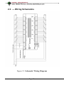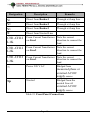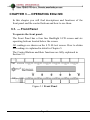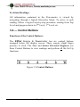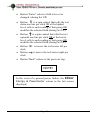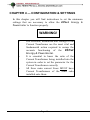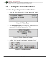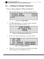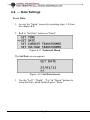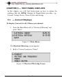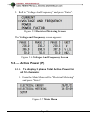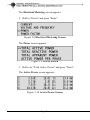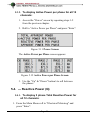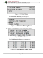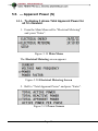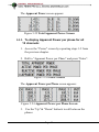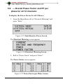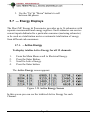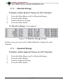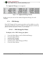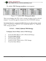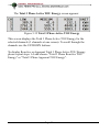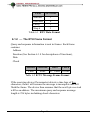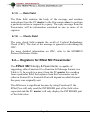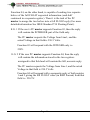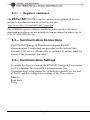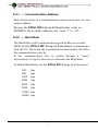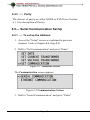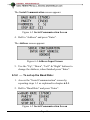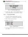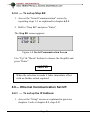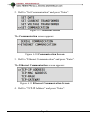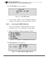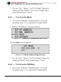
1
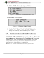
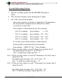
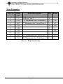
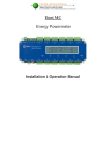
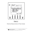
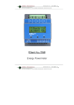
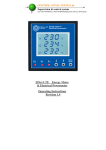
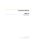
Elnet MC
Energy Powermeter
Installation & Operation Manual
Table of Content
CHAPTER 1 ─ INTRODUCTION ...................................................... 4
1.1.
- About the ELNet MC Energy & Powermeter........... 4
1.2.
— How to use this manual ................................................... 5
1.3.
— Safety Information ........................................................... 6
1.4.
— Warranty .......................................................................... 7
1.5.
— Your comments are welcome ........................................... 9
1.6.
— Disclaimer ....................................................................... 10
CHAPTER 2 — INSTALLATION ..................................................... 11
2.1.
— Contents of packaging ................................................... 11
2.2.
— Mechanical Mounting .................................................... 12
2.3.
— Wiring Schematics ......................................................... 13
2.4.
— Connections .................................................................... 14
CHAPTER 3 — OPERATING ElNet MC ......................................... 16
3.1.
— Front Panel ..................................................................... 16
3.2.
— Control Buttons .............................................................. 17
CHAPTER 4 — CONFIGURATION & SETTINGS ........................ 19
4.1.
— Settings for Current Transformer ................................ 20
4.2.
— Settings for Voltage Transformer .................................. 22
4.3.
— Time Settings .................................................................. 23
4.4.
— Date Settings................................................................... 24
CHAPTER 5 — TEXT PANEL DISPLAYS ...................................... 25
5.1.
— Current Displays ............................................................ 25
5.2.
— Voltage and Frequency Displays ................................... 26
5.3.
— Active Power (P) ............................................................. 27
5.3.1. To display 3 phase Total Active Power for all 12
channels: ........................................................................................ 27
5.3.2.
5.4.
To display Active Power per phase for all 12 channels: 29
— Reactive Power (Q) ........................................................ 29
5.4.1. To display 3 phase Total Reactive Power for all 12
channels: ........................................................................................ 29
5.4.2.
5.5.
To display Reactive Power per phase for all 12 channels:
31
— Apparent Power (S)........................................................ 32
5.5.1. To display 3 phase Total Apparent Power for all 12
channels: ........................................................................................ 32
5.5.2. To display Apparent Power per phase for all 12
channels: ........................................................................................ 33
5.6. — Overall Power Factor and PF per phase for all 12
channels: ........................................................................................ 34
5.7
— Energy Displays ............................................................. 35
5.7.1.
– Active Energy ............................................................... 35
5.7.2.
– Reactive Energy............................................................ 36
5.7.3.
– Apparent Energy .......................................................... 36
5.7.4.
– TOU Energy .................................................................. 37
5.7.4.1.
– TOU Energy Per Phase............................................. 37
5.7.4.2.
– Total (3 phase) TOU Energy .................................... 38
CHAPTER 6 — COMMUNICATION ............................................... 40
6.1
— MODBUS Framing ........................................................ 40
6.1.1
— RTU Transmission Mode ........................................... 40
6.1.2
— The RTU Frame Format ............................................ 41
6.1.3
— Address Field .............................................................. 42
6.1.4
— Function Field ............................................................. 42
6.1.5
— Data Field .................................................................... 43
6.1.6
— Check Field ................................................................. 43
6.2
6.2.1
— Registers for ElNet MC Powermeter ............................ 43
— Registers addresess .................................................... 45
6.3
— Communication Connections ........................................ 45
6.4
— Communication Settings ............................................... 45
6.4.1
— Communication Address ............................................ 46
6.4.2
— Baud Rate ................................................................... 46
6.4.3
— Parity ........................................................................... 47
6.5
— Serial Communication Set Up ....................................... 47
6.5.1
— To set up the Address: ................................................ 47
6.5.2
— To set up the Baud Rate: ............................................ 48
6.5.3
— To set up the Parity: ................................................... 49
6.5.4
— To set up Stop Bit: ...................................................... 50
6.6
— Ethernet Communication Set UP. ................................. 50
6.6.1
— To set up the IP Address: ........................................... 50
6.6.2
— To set up the MAC Address: ...................................... 52
6.6.3
— To set up the Mask: .................................................... 53
6.6.4
— To set up the GateWay: .............................................. 53
6.7
— Communication with UniArt Software ........................ 54
CHAPTER 7 — SPECIFICATIONS................................................. 57
CHAPTER 1 ─ INTRODUCTION
1.1. - About the ELNet MC Energy & Powermeter
All large consumers of electricity e.g. Factories, Hotels,
Hospitals, Municipalities, need to know the history of their
consumption and the quality of the power supply. Details such as
Voltage, Current, Power Factor, Hertz, Neutral Current, Energy
Demands and all electricity related events are recorded in the
ElNet Energy & Powermeter. These are all recorded on a
continual basis and can be recalled and shown on the front panel
TEXT display of the instrument with a few simple key-strokes
any time the user wishes.
The ElNet Energy & Powermeter installs onto a standard DIN
Rail, and is especially designed to integrate into Building
Management Systems.
The Configuration and Setup is menu driven.
Communication with external devices is simple and based on
standard known technology.
The ElNet Energy & Powermeter boasts a new innovative built
in “Flash Memory”, which pioneers a new frontier into electrical
measurement. It has a 1 MB of ROM with a capacity of recording
up to 4 months of energy for each channel.
Page 4
Each ElNet Energy & Power Powermeter is carefully and
meticulously manufactured using quality components and the
latest production methods. Before leaving the factory each ElNet
Energy & Powermeter is calibrated and sent to the customer
accompanied by the test certificate and Certificate Of Compliance
(C.O.C).
1.2. — How to use this manual
We at CONTROL APPLICATIONS Ltd, envisage this manual to
be used by three types of people, i.e. the Installation Technician,
the Senior Electrical Engineer and the end User. For this reason
this manual is divided into chapters for ease of reference by each
of these different people. There could be a situation where two of
the abovementioned tasks can be combined, or in a rare instance
one person could handle all three tasks.
CHAPTER 1, Introduction, describes the ElNet Energy &
Powermeter, its potential users, the readings it can provide and
some of its features in brief.
CHAPTER 2, Installation, provides detailed instructions for
unpacking, mechanical mounting, and electrical wiring up
instructions for the Installation Technician.
CHAPTER 3, Operating the ElNet MC, describes in detail the
front Panel, functions of the control buttons.
CHAPTER 4, CONFIGURATION & SETTINGS explains in detail
the minimum parameters settings needed by the Senior Electrical
Engineer to set up and configure the ElNet Energy &
Powermeter.
Page 5
CHAPTER 5, Front Panel Displays, is an easy to follow step-bystep guide to obtain readings, and histories for the User.
CHAPTER 6, Communications gives details about the
Communication capabilities of the ElNet Energy &
Powermeter, and how to Set Up.
CHAPTER 7, Specifications, is a detailed list of specifications of
the ElNet Energy & Powermeter.
1.3. — Safety Information
The purpose of this manual is to help you. Please read the
instructions carefully before performing any installation and note
any precautions.
WARNING!
•
•
•
Ensure that all incoming AC power and other
power sources are turned off before
performing any work on the ElNet Energy
& Powermeter. Failure to do so may result in
serious or even fatal injury and/or equipment
damage.
If the ElNet Energy & Powermeter is
damaged in any way do NOT connect it to
any power source.
To prevent a potential fire or shock hazard,
never expose the ElNet Energy &
Powermeter to rain or moisture.
Page 6
•
Keep the surrounding area free of dirt and
clutter especially metal objects. Good
housekeeping pays.
•
Inspect the cables periodically for cracks,
kinks or any other signs of wear
Keep children away.
Do not pull the cords.
•
•
•
•
•
Users should stay alert and not approach the
rear of the ElNet Energy & Powermeter
while tired or under the influence of alcohol,
medicines or any other chemical substance
that would tend to make a person drowsy.
Do not wear loose clothing or dangling
jewelry.
Above all use common sense at all times.
1.4. — Warranty
CONTROL APPLICATIONS Ltd provides a 12- Month warranty
against faulty workmanship or components from date of dispatch
provided that the product was properly installed and used.
CONTROL APPLICATIONS Ltd does not accept liability for any
damage that may be caused by natural disasters (such as floods,
fire, earthquake, lightening etc.).
CONTROL APPLICATIONS Ltd does not accept liability for any
damage that may be caused by malfunction of the ElNet Energy
& Powermeter.
Page 7
CONTROL APPLICATIONS Ltd will advise the customer on the
proper installation and use of the ElNet Energy & Powermeter,
but will not accept any responsibility that the instrument is
suitable for the application for which it was originally purchased.
This warranty may become void if the installation, parameter
configuration & setting instructions are not carried out according
to the instructions set out by CONTROL APPLICATIONS Ltd.
The ElNet Energy & Powermeter has no user serviceable parts
and should be opened and serviced by a duly qualified authorized
representative only. The sensitive electronics could be damaged if
exposed to a static environment. This action would void the
warranty.
This warranty is limited to the repair and/or replacement at
CONTROL APPLICATION Ltd sole discretion of the defective
product during the warranty period. Repaired or replaced products
are warranted for ninety (90) days from the date of repair or
replacement, or for the remainder of the original product’s
warranty period, whichever is longer.
CONTROL APPLICATIONS Ltd is always at your service to
advise the customer on any problem that may be encountered
regarding any installation, operation, parameter & configuration
settings or maintenance.
Page 8
1.5. — Your comments are welcome
CONTROL APPLICATIONS Ltd. Sincerely thank you for
choosing our ElNet Energy & Powermeter. We are confident
that it will provide you with many years of trouble free service
and give you all the power and energy information and history
that you expected from the instrument when you bought it.
While every effort was made to keep the information as reliable,
helpful, accurate and up to date as possible, all possible
contingencies cannot be covered. Technical or typographical
errors could occur, and we would be happy to receive any
comments criticisms or notifications of any such errors from you,
our valued customer.
Street Address:
Electronic Address:
24A HaBarzel St.
Tel-Aviv 69710
Israel
Tel: 972-3-647-4998
Fax: 972-3-647-4598
[email protected]
Page 9
1.6. — Disclaimer
Information in this User Manual is subject to change without
notice and does not represent a commitment on the part of
CONTROL APPLICATIONS Ltd.
CONTROL APPLICATIONS Ltd supplies this User Manual as is
without warranty of any kind; either expressed or implied, and
reserves the right to make improvements and/or changes in the
manual or the product at any time.
While it is the intension of CONTROL APPLICATIONS Ltd to
supply the customer with accurate and reliable information in this
User Manual, CONTROL APPLICATIONS Ltd assumes no
responsibility for its use, or for any infringement of rights of the
fourth parties which may result from its use.
This User Manual could contain technical or typographical errors
and changes are periodically made to the information herein;
these changes may be incorporated in new editions of the
publication.
Page 10
CHAPTER 2 — INSTALLATION
In this Chapter you will find the information and instructions that
the Installation Technician needs to mount and connect the
ELNet Energy & Powermeter
WARNING!
•
•
•
•
During operation, hazardous voltages are present in
connecting cables and terminal blocks.
Fully qualified personnel must do all work. Failure to
follow this rule may result in serious or even fatal
injury to personnel and/or damage to equipment.
Refer to Section 1.3 Safety information before carrying
out any installation.
Read this manual thoroughly and make sure you
understand the contents before connecting the ElNet
Energy & Powermeter to any power source.
2.1. — Contents of packaging
To unpack the ElNet Energy & Powermeter:
The ElNet Energy & Powermeter is packed and shipped in a
carton approximately 32 cm long X 22 cm wide and 7.5 cm high.
Page 11
Before opening the package, ensure the area is static free clean
and dry.
Without using any sharp instruments, carefully open the carton of
the ElNet Energy & Powermeter.
Please check the contents of the carton, it should contain:
1.
2.
3.
4.
5.
6.
Your new ElNet MC Energy & Powermeter.
ElNet MC User Manual. (This book)
Test Certificate and Certificate of Compliance. (C.O.C)
12 X six pole connector plugs.
1 X three pole connector plugs.
1 X two pole connector plugs.
2.2. — Mechanical Mounting
NOTE!
Do not mount the ElNet Energy & Powermeter
too close to any main electrical conductors.
Allow sufficient space to carry out maintenance to the
ElNet Energy & Powermeter
The ElNet Energy & Powermeter is manufactured with a
standard DIN rail mounting. To mount, simply choose a suitable
location and click into position.
Page 12
2.3. — Wiring Schematics
Figure 2.1 Schematic Wiring Diagram
Page 13
2.4. — Connections
To connect the ElNet Energy & Powermeter:
All Connections are made via terminal connector plugs (Voltage
input, Power Supply, earth/ground etc.).
Recommended maximum tightening torque for the connector screws
is 0.5 Nm.
The CT cores of the ElNet Energy & Powermeter are located
internally in the instrument and the lead from the leg of the
external Current Transformer must be connected to the correct
terminal connector in order to maintain the correct direction.
NOTE!
Ensure all the connections to the leads of the current
transformer wiring is secure and there is no mechanical
strain on the wire
Connect the lead from side “L” to the terminal connector L1 at
the relevant channel, connect the lead from side “K” to the
terminal connector K at the same channel, of the ElNet
Energy & Powermeter.
WARNING!
WARNING
Never allow an open circuit between the two Current
Transformers.
An open circuit will cause damage to equipment.
Repeat the procedure for Line 2 and Line 3.
Connect the rest the connections to the ElNet Energy &
Powermeter by means of terminal connector plugs.
Page 14
Designation
Description
Remarks
V1
Direct from Busbar1
Through a 6Amp fuse
V2
Direct from Busbar2
Through a 6Amp fuse
V3
Direct from Busbar3
Through a 6Amp fuse
N
Direct from Neutral Line
CH1-CH12
L1K
From Current Transformer Note the correct
on Line1
direction to connect the
lead
CH1-CH12
L2K
From Current Transformer Note the correct
on Line2
direction to connect the
lead
CH1-CH12
L3K
From Current Transformer Note the correct
on Line3
direction to connect the
lead
~
Power 220 V AC
Np
Neutral
Bridged from
measured phase or
external AC\DC
supply source
Bridged from the
neutral Line or
external AC\DC
supply source
Table 2.1 Front Panel Connections
Page 15
CHAPTER 3 — OPERATING ElNet MC
In this chapter you will find descriptions and functions of the
front panel and the control buttons and how to use them.
3.1. — Front Panel
To operate the front panel:
The Front Panel has a four line Backlight LCD screen and six
operating buttons located below the screen.
All readings are shown on the 4 X 40 text screen. How to obtain
the readings is explained in detail in Chapter 5.
The Control Buttons and their functions are fully explained in
Section 3.2.
Figure 3.1 Front Panel
Page 16
To obtain Readings:
All information contained in the Powermeter is viewed by
navigating through a logical Hierarchy Menu. To arrive at each
reading, follow a logical step-by-step procedure starting from Top
Level and progress down to 2nd Level, 3rd Level etc.
3.2. — Control Buttons
Functions of the Control Buttons:
The ElNet Energy & Powermeter has six control buttons
arranged below the display screen. These require slight finger
pressure to click. The User and Senior Electrical Engineer use
these Control Buttons to view readings and perform all the Set Up
functions.
Figure 3.2 Control Buttons
Page 17
•
Button "Enter" selects a field to be set or
changed. (during Set UP)
•
Button
is a spin control that rolls the text
down one line per click OR at the highest
level, rolls to each reading of that group OR
modifies the selected field (during Set UP).
•
Button
is a spin control that rolls the text
upwards one line per click OR at the lowest
level, rolls to each reading of that group OR
modifies the selected field (during Set UP).
Button
is moves the text\cursor left per
click.
Button
is moves the text\cursor right per
click.
Button "Back" returns to the previous step.
•
•
•
NOTE!
In the event of a general power failure, the ElNet
Energy & Powermeter returns to the last screen
displayed.
Page 18
CHAPTER 4 — CONFIGURATION & SETTINGS
In this chapter you will find instructions to set the minimum
settings that are necessary to allow the ElNet Energy &
Powermeter to function properly.
WARNING!
•
•
•
The selection, installation and settings of the
Current Transformer are the most vital and
fundamental action required to ensure the
accurate functioning of the ElNet
Energy & Powermeter.
It is essential to know the ratio of the
Current Transformer being installed into the
system in order to set the parameter for the
Current Transformer correctly.
All three main current Lines MUST have
Current Transformers of the same ratio
installed onto them.
Page 19
4.1. — Settings for Current Transformer
To set or change settings for Current Transformer:
1. From the Main Menu roll to "Setup" and click "Enter".
Figure 4.1 Main Menu
2. The Enter Password screen appears, please insert the
password. (The default password is "1")
Figure 4.2 Enter Password Screen
3. Roll to "Set Current Transformer" and click "Enter".
Figure 4.3 Technical Menu
Page 20
The Current Transformer screen appears. In this screen
you can define each and every chanell's current transformer,
or by scrolling to the buttom line you can define all at once.
4. In order to define the CT rate of the relevant channel,
scroll down to the desirable channel and click "Enter".
Figure 4.4 Current Transformer Screen
5. The Set Current Transformer Ratio screen appears,
use the:
buttons to change the value, when finished click "Enter".
Figure 4.5 Current Transformer Ratio Input Screen
In order to set all the CT rates at once, to one fixed value
scroll to "Current Transformer (ALL)" and repeat step 5.
Page 21
4.2. — Settings for Voltage Transformer
To set or change settings for Voltage Transformer:
1. From the Main Menu roll to "Setup" and click "Enter".
Figure 4.6 Main Menu
2. The Enter Password screen appears, please insert the
password. (The default password is "1")
Figure 4.7 Enter Password Screen
3. Roll to "Set Voltage Transformer" and click "Enter".
Figure 4.8 Technical Menu
4. Change the ratio of the Voltage Transformer according
to the demand, when finished click "Enter".
Page 22
4.3. — Time Settings
To set Time:
1. Access the "Setup" screen by repeating steps 1-2 from
the previous chapter.
2. Roll to "Set Time" and press "Enter".
Figure 4.9 Technical Menu
The Set Clock screen appears:
Figure 4.10 Set Clock Screen
3. Use the "Left" , "Right" , "Up" & "Down" buttons to
setup the clock, when finished press "Enter".
Page 23
4.4. — Date Settings
To set Date:
1. Access the "Setup" screen by repeating steps 1-2 from
the chapter 4.2.
2. Roll to "Set Date" and press "Enter".
Figure 4.11 Technical Menu
The Set Date screen appears:
Figure 4.12 Set Date Screen
3. Use the "Left" , "Right" , "Up" & "Down" buttons to
setup the Date, when finished press "Enter".
Page 24
CHAPTER 5 — TEXT PANEL DISPLAYS
In this chapter you will find instructions on how to obtain the
readings that the ElNet Energy & Powermeter provides, e.g.,
Current, Voltage Power, Power Factor and Energy.
5.1. — Current Displays
To display Current for all 3 Phases per channel:
1. From the Main Menu roll to "Electrical Metering" and
press "Enter".
Figure 5.1 Main Menu
The Electrical Metering screen appears:
2. Roll to "Current" and press "Enter".
Figure 5.2 Electrical Metering Screen
Page 25
The Current screen appears:
Figure 5.3 Current Screen
3. Use the up\down buttons to roll between the channel
readings.
5.2. — Voltage and Frequency Displays
To display Voltage and Frequency for all 3 Phases:
1. From the Main Menu roll to "Electrical Metering" and
press "Enter".
Figure 5.4 Main Menu
The Electrical Metering screen appears:
Page 26
2. Roll to "Voltage And Frequency" and press "Enter".
Figure 5.5 Electrical Metering Screen
The Voltage and Frequency screen appears:
Figure 5.6 Voltages And Frequency Screen
5.3. — Active Power (P)
5.3.1. To display 3 phase Total Active Power for
all 12 channels:
1. From the Main Menu roll to "Electrical Metering"
and press "Enter".
Figure 5.7 Main Menu
Page 27
The Electrical Metering screen appears:
2. Roll to "Power" and press "Enter".
Figure 5.8 Electrical Metering Screen
The Power screen appears:
Figure 5.9 Power Screen
3. Roll to to "Total Active Power" and press "Enter".
The Active Power screen appears:
Figure 5.10 Active Power Screen
Page 28
5.3.2. To display Active Power per phase for all 12
channels:
1. Access the "Power" screen by repeating steps 1-2
from the previous chapter.
2. Roll to "Active Power per Phase" and press "Enter".
Figure 5.11 Power Screen
The Active Power per Phase screen appears:
Figure 5.12 Active Power per Phase Screen
3. Use the "Up" & "Down" button's to roll between
the phases.
5.4. — Reactive Power (Q)
5.4.1. To display 3 phase Total Reactive Power for
all 12 channels:
1. From the Main Menu roll to "Electrical Metering" and
press "Enter".
Page 29
Figure 5.13 Main Menu
The Electrical Metering screen appears:
Figure 5.14 Electrical Metering Screen
2. Roll to "Total Reactive Power" and press "Enter".
Figure 5.15 Power Screen
The Total Reactive Power screen appears:
Figure 5.16 Total Reactive Power Screen
Page 30
5.4.2. To display Reactive Power per phase for all
12 channels:
1. Access the "Power" screen by repeating steps 1-2
from the previous chapter.
2. Roll to "Reactive Power per Phase" and
press "Enter".
Figure 5.17 Power Screen
The Reactive Power per Phase screen appears:
Figure 5.18 Reactive Power per Phase Screen
3. Use the "Up" & "Down" button's to roll between
the phases.
Page 31
5.5. — Apparent Power (S)
5.5.1. To display 3 phase Total Apparent Power for
all 12 channels:
1. From the Main Menu roll to "Electrical Metering"
and press "Enter".
Figure 5.19 Main Menu
The Electrical Metering screen appears:
Figure 5.20 Electrical Metering Screen
2. Roll to "Total Apparent Power" and press "Enter".
Figure 5.21 Power Screen
Page 32
The Apparent Power screen appears:
Figure 5.22 Total Apparent Power Screen
5.5.2. To display Apparent Power per phase for all
12 channels:
1. Access the "Power" screen by repeating steps 1-2 from
the previous chapter.
2. Roll to "Apparent Power per Phase" and press "Enter".
Figure 5.23 Power Screen
The Apparent Power per Phase screen appears:
Figure 5.24 Apparent Power per Phase Screen
3. Use the "Up" & "Down" button's to roll between the
phases.
Page 33
5.6. — Overall Power Factor and PF per
phase for all 12 channels:
To display the Power Factor for all 3 Phases:
1. From the Main Menu roll to "Electrical Metering" and
press "Enter".
Figure 5.25 Total Reactive Power Screen
The Electrical Metering screen appears:
Figure 5.26 Electrical Metering Screen
2. Roll to "Power Factor" and press "Enter".
The Power Factor screen appears:
Figure 5.27 Power Factor per Phase Screen
Page 34
3. Use the "Up" & "Down" button's to roll
between the phases.
5.7 — Energy Displays
The Elnet MC Energy & Powermeter provides up to 36 submeters with
separate measurement and energy registers. Each submeter can service
current inputs dedicated to a particular consumer (metering submeter)
or be used as a totalization meter or automatic totalization of energy
from different sub-consumers.
5.7.1. – Active Energy
To display totalize Active Energy for all 12 channels:
1.
2.
3.
4.
From the Main Menu scroll to Electrical Energy.
Press the Enter Button.
Scroll to Active Energy.
Press the Enter button.
The Active Energy screen appears:
Figure 5.28 Active Energy Screen
In this screen you can see the totalized Active Energy for each
Channel.
Page 35
5.7.2. – Reactive Energy
To display totalize Reactive Energy for all 12 channels:
1.
2.
3.
4.
From the Main Menu scroll to Electrical Energy
Press the Enter Button
Scroll to Reactive Energy
Press the Enter button
The Reactive Energy screen appears:
Figure 5.29 Reactive Energy Screen
In this screen you can see the totalized Reactive Energy for each
Channel.
5.7.3. – Apparent Energy
To display totalize Apparent Energy for all 12 channels:
1.
2.
3.
4.
From the Main Menu scroll to Electrical Energy.
Press the Enter Button.
Scroll to Apparent Energy.
Press the Enter button.
Page 36
The Apparent Energy screen appears:
Figure 5.30 Apparent Energy Screen
In this screen you can see the totalized Apparent Energy for each
Channel.
5.7.4. – TOU Energy
Elnet MC Energy & Powermeter provides you the ability to see the
information about the energy by TOU for each channel in detail (by
phase) and the summarize value of each channel.
5.7.4.1. – TOU Energy Per Phase
To display Active TOU Energy per phase:
1.
2.
3.
4.
5.
6.
From the Main Menu scroll to Electrical Energy.
Press the Enter Button.
Scroll to TOU Energy.
Press the Enter button.
Scroll to Active TOU Energy per Phase.
Press the Enter Button.
Page 37
The Active TOU Energy per phase screen appears:
Figure 5.31 Active TOU Energy per phase
This screen displays the TOU Active energy per phase for the selected
channel. To scroll through the channels use the UP/DOWN buttons.
To display Reactive or Apparent TOU Energy per phase please repeat
steps 1-4 and choose "Reactive TOU Energy per phase" or "Apparent
TOU energy per phase".
5.7.4.2. – Total (3 phase) TOU Energy
To display Total 3 Phase Active TOU Energy:
1.
2.
3.
4.
5.
6.
From the Main Menu scroll to Electrical Energy.
Press the Enter Button.
Scroll to TOU Energy.
Press the Enter button.
Scroll to Total 3 Phase Active TOU Energy.
Press the Enter Button.
Page 38
The Total 3 Phase Active TOU Energy screen appears:
Figure 5.32 Total 3 Phase Active TOU Energy
This screen displays the Total 3 Phase Active TOU Energy for the
selected channels (3 channels at one screen). To scroll through the
channels use the UP/DOWN buttons.
To display Reactive or Apparent Total 3 Phase Active TOU Energy
please repeat steps 1-4 and choose "Total 3 Phase Reactive TOU
Energy" or "Total 3 Phase Apparent TOU Energy".
Page 39
CHAPTER 6 — COMMUNICATION
MODBUS Protocol:
The Elnet MC Energy & Powermeter has a serial and
TCP/IP interface ports, allowing direct interface with an external
communication network supporting the MODBUS Protocol.
MODBUS is an Industry Standard, widely known and commonly
used communications protocol. Using MODBUS provides
communication between a PC and up to 247 Powermeter slaves on a
common line - the PC being the master and the powermeters the
slaves. The PC initiates the transaction (either a query or broadcast)
and the Powermeter/s responds. Powermeters respond to the master
PC’s request, but will not initiate any transmission on its own. The
PC sends a single Query transaction and the Powermeter responds in
a single response frame and is capable of only one query and one
response at a time.
6.1 — MODBUS Framing
6.1.1 — RTU Transmission Mode
MODBUS uses the standard Remote Terminal Unit (RTU)
transmission mode. RTU mode sends data in 8-bit binary EVEN
parity or 8-bit binary NO parity data format. For the Elnet MC
Energy & Powermeter to successfully communicate, choose one in
the communication Set Up.
Page 40
Field
No. of bits
Start bit
Data bits
Parity
Stop it
1
8
1
1
Table 6.1 RTU Data Format
6.1.2 — The RTU Frame Format
Query and response information is sent in frames. Each frame
contains:
Address
Function (See Section 6.1.4 for descriptions of functions),
Data
Check
Address Function
Data
Check
8 bits
8 bits
N * 8 bits 16 bits
Table 6.2 R T U Message Frame Format
If the receiving device (Powermeter) detects a time laps of five
characters, then it will assume the message is incomplete and will
flush the frame. The device then assumes that the next byte received
will be an address. The maximum query and response message
length is 256 bytes includuing check characters.
Page 41
6.1.3 — Address Field
Each Powermeter is designated in a network system by a user
assigned address. The Address can be any number between 1 and
247. The Powermeter will only respond to its own specifically
assigned address.
6.1.4 — Function Field
The function field contains the code that tells the Powermeter what
action to perform.
The ElNet MC Energy & Powermeter uses and responds to four
standard Message Format Functions.
Function 03
Function 04
Function 06
Function 16
Function
Function 03
Function 04
Function 06
Function 16
Meaning in MODBUS
Read holding register
Action
Obtain data from Powermeter
(Read register)
Read input register
Obtain data from Powermeter
(Read register)
Preset single register
Transmit data to Powermeter
(Write single register)
Preset multiple register Transmit data to Powermeter
(Write multiple register)
Table 6.3 Function Codes
Page 42
6.1.5 — Data Field
The Data field contains the body of the message and contains
instructions from the PC master to the Powermeter slave to perform
a particular action or respond to a query. The reply message from the
Powermeter will be information contained in one or more of its
registers.
6.1.6 — Check Field
The error check field contains the result of Cyclical Redundancy
Check (CRC). The start of the message is ignored in calculating the
CRC.
For more detailed information on CRC, refer to the MODBUS
Protocol Reference Guide.
6.2 — Registers for ElNet MC Powermeter
The ElNet MC Energy & Powermeter is capable of
supporting either Function 03 or Function 04 Message Format (see
Table 6-3). In a reply to a query from the PC master for a reading
from a particular field, the response from the Powermeter can be
either in Format 03 or Format 04 but will depend on which Format
the query was originally sent.
The difference is significant because by using Function 03 the
ElNet Pico will only send the INTERGER part of the field value
requested and the PC master will only display the INTERGER part
of the field value.
Page 43
Function 04, on the other hand, is capable of sending two separate
halves of the full FLOAT requested information (each half
contained in a separate register). Then it is the task of the PC
master to merge the two halves into a full FLOAT reply (For more
detailed information See IEEE Standard 754 Floating-Point).
E.G. 1 If the user’s PC master supports Function 03, then the reply
will contain the INTERGER part of the field only.
The PC master requests the Voltage from Line1, and the
actual Voltage in that field is 230.5 Volts.
Function 03 will respond with the INTEGER only i.e.
230V.
E.G. 2 If the user PC master supports Function 04, then the reply
will contain the information stored in the two registers
asssigned to that field and will contain the full, accurate reply.
The PC master requests the Voltage from Line1, and the actual
Voltage in that field is 230.5 Volts.
Function 04 will respond with a composite reply of both register
1 and 2 giving the full FLOAT value (in IEEE Format) from that
field i.e. 230.5V.
Page 44
6.2.1 — Registers addresess
The ElNet MC MODBUS registers addresses are updated all the time
and can be downloaded from the following web site:
http://www.ddc.co.il/elnet-pdf/elnet_comm.pdf
The MODBUS registers addresses numbering order specify at the above
mentioned web address set as a defaults but can be changed in order to be fit
to the SCADA/HMI drivers.
6.3 — Communication Connections
The ElNet MC Energy & Powermeter supports RS-485
communication. Connections are provided on the bottom front
terminal of the device. (Please refer to section 2.4) and are made by
means of the connectors provided.
6.4 — Communication Settings
To enable the User to connect the ElNet MC Energy & Powermeter
to a PC computer for successful communications, the
Communication Setup parameters of both must match; i.e. the port
of the PC and the configuration settings of the Power meter.
Address
Baud Rate
Parity
Page 45
6.4.1 — Communication Address
Each Power meter in a communication system must have its own
unique address.
Because the ElNet MC Energy & Powermeter works on
MODBUS, the available addresses are - from ‘1’ to ‘247’.
6.4.2 — Baud Rate
The Baud Rate is the communication speed in Bits per second
(BPS) that the ElNet MC Energy & Powermeter communicates
with the PC. The better the communication line Quality, the faster
the communications may be.
If the communication line is routed through a “noisy”
environment, it may be necessary to decrease the Baud Rate.
Available Baud Rates for the ElNet MC Energy & Powermeter:
300
600
1200
2400
4800
9600
19200
38400
bps
bps
bps
bps
bps
bps
bps
bps
Page 46
6.4.3
— Parity
The choices of parity are either NONE or EVEN (see Section
6.1.1 for description of Parity).
6.5 — Serial Communication Set Up
6.5.1 — To set up the Address:
1. Access the "Setup" screen as explained in previous
chapters. Look at chapter 4.1, steps 1-2.
2. Roll to "Set Communication" and press "Enter".
Figure 6.1 Technical Screen
The Communication screen appears:
Figure 6.2 Communication Screen
3. Roll to "Serial Communication" and press "Enter".
Page 47
The Serial Communication screen appears:
Figure 6.3 Serial Communication Screen
4. Roll to "Address" and press "Enter".
The Address screen appears:
Figure 6.4 Address Input Screen
5. Use the "Up", "Down", "Left" & "Right" buttons to
change the Address, when finished press "Enter".
6.5.2 — To set up the Baud Rate:
1. Access the "Serial Communication" screen by
repeating steps 1-3 as explained in chapter 6.5.1.
2. Roll to "Baud Rate" and press "Enter".
Figure 6.5 Serial Communication Screen
Page 48
The Baud Rate screen appears:
Figure 6.6 Baud Rate Input Screen
3. Use the "Up", "Down", "Left" & "Right" buttons to
change the Baud Rate, when finished press "Enter".
6.5.3 — To set up the Parity:
1. Access the "Serial Communication" screen by
repeating steps 1-3 as explained in chapter 6.5.1.
2. Roll to "Parity" and press "Enter".
The Parity screen appears:
Figure 6.7 Parity Screen
3. Use "Up" & "Down" buttons to choose the Parity and
press "Enter".
Page 49
6.5.4 — To set up Stop Bit:
1. Access the "Serial Communication" screen by
repeating steps 1-3 as explained in chapter 6.5.1.
2. Roll to "Stop Bit" and press "Enter".
The Stop Bit screen appears:
Figure 6.8 Serial Communication Screen
Use "Up" & "Down" buttons to choose the Stop Bit and
press "Enter".
NOTE!
When the selection is made it takes immediate affect
with no further action required.
6.6 — Ethernet Communication Set UP.
6.6.1 — To set up the IP Address:
1. Access the "Setup" screen as explained in previous
chapters. Look at chapter 4.1, steps 1-2.
Page 50
2. Roll to "Set Communication" and press "Enter".
Figure 6.9 Technical Screen
The Communication screen appears:
Figure 6.10 Communication Screen
3. Roll to "Ethernet Communication" and press "Enter".
The Ethernet Communication screen appears:
Figure 6.11 Ethernet Communication Screen
4. Roll to "TCP-IP Address" and press "Enter".
Page 51
The Set IP Address screen appears:
Figure 6.12 Set IP Screen
5. Use the "Up", "Down", "Left" & "Right" buttons to
change the IP address, when finished press "Enter".
6.6.2 — To set up the MAC Address:
1. Access the "Ethernet Communication" screen by
repeating steps 1-3 as explained in chapter 6.6.1
2. Roll to "TCP-Mac" Address and press "Enter".
Figure 6.13 Ethernet Communication Screen
The Mac Address screen appears:
Figure 6.14 Mac Address Input Screen
Page 52
3. Use the "Up", "Down", "Left" & "Right" buttons to
change the Mac Address (3 last sets of digits only),
when finished press "Enter".
6.6.3 — To set up the Mask:
1. Access the "Ethernet Communication" screen by
repeating steps 1-3 as explained in chapter 6.6.1
2. Roll to "TCP-Mask" and press "Enter".
Figure 6.15 Ethernet Communication Screen
The Set Mask screen appears:
Figure 6.16 Mask Address Input Screen
3. Use the "Up", "Down", "Left" & "Right" buttons to
change the Mask, when finished press "Enter".
6.6.4 — To set up the GateWay:
1. Access the "Ethernet Communication" screen by
repeating steps 1-3 as explained in chapter 6.6.1
Page 53
2. Roll to "TCP – Gateway" and press "Enter".
Figure 6.17 Ethernet Communication Screen
The Gateway screen appears:
Figure 6.18 Gateway Input Screen
3. Use the "Up", "Down", "Left" & "Right" buttons to
change the Gateway, when finished press "Enter".
6.7 — Communication with UniArt Software
CONTROL APPLICATIONS Ltd propriety software, “UniArt” is
used to Read and Write Registers of the ElNet MC Energy &
Powermeter. Each Item number in the Registers Table is a
unique field containing information. The UniArt software
manages each Item number as a parameter.
Refer to the UniArt manual how to set up parameters.
Page 54
To read fields using UniArt:
1. Find the reading required in the MODBUS Registers
Table.
2. Note the Item Number from the Registers Table.
3. Go to the correct File number.
Since File capacity in UniArt is limited to 128 parameters,
the information contained in the ElNet Pico fields
is stored in several files.
File number is determined by the Item number
File # 0 contains
Item number
File # 1 contains
Item number 129 – 256
File # 2 contains
Item number 257 – 384
1 - 128
File # 3 contains Item number 385 – 512
Go to the correct Point number within that file
Point number is determined by the formula:
Item number – [FILE X 128] = Point Number
E.G. 1 If the user the wishes to read Voltage Line 2 (Item No 2)
By applying the formula: 2 - [0 X 128] = 2
File = 0 and Point within that file = 2
E.G. 2 If the user the wishes to read 30th Harmonics for Volts Line1
(Item No 330)
By applying the formula: 330 - [2 X 128] = 74
File = 2 and Point within that file = 74
E.G. 3 If the user the wishes to read 7th Harmonic for Current Line 3
(Item No 467)
By applying the formula: 467 - [3 X 128] = 83
File = 3 and Point number within that file = 83
Page 55
More Examples:
E.G. No
Item
No
Field Description
File
Point
1
2
3
4
5
6
7
8
9
2
330
467
128
129
256
257
384
385
Voltage Line 2
30th Harmonics for Volts Line1
7th Harmonic for Current Line 3
0
2
3
0
1
1
2
2
3
2
74
83
128
1
128
1
128
1
20th Harmonics for Volts Line 3
21st Harmonics for Volts Line3
Table 6.4 Function Codes
Page 56
CHAPTER 7 — SPECIFICATIONS
Item
Description
Power requirements
85-250VAC, 60/50 Hz, 60VA
Dimensions
(HxWxD) 110x300x60 mm
Shipping Weight
1,250 gr
Voltage limits
1000VAC
Current limits
20A
Enclosure material
ABS + Antiflame
Display
Liquid Crystal 4 X 40
Operating temperature
-20 - + 60 C
Storage temperature
-20 - + 80 C
Humidity
0- 90 RH%
Voltage input terminals
VL – E10 1708
Communication port
RS485, Ethernet TCP\IP
Mounting
Standard DIN Rail
Digital Inputs (optional)
Dry contact
All technical specifications are subject to change without notice.
Page 57