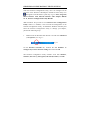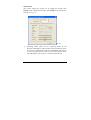
1
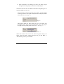
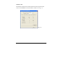
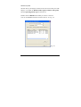
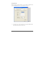
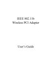
IEEE 802.11b
Pen Size Wireless
USB Adapter
User’s Manual
Regulatory Notes and Statements
Health and Authorization for Use
Radio frequency electromagnetic energy is emitted from the Wireless LAN
device. The energy levels of these emissions are much less than the
electromagnetic energy emissions from wireless devices such as cell phones.
Wireless LAN devices are safe for use and meet the frequency safety
standards and recommendations. The use of Wireless LAN devices may be
restricted in some situations or environments such as:
•
•
•
On board of airplanes, or
In an explosive environment, or
In case the interference risk to other devices or services is perceived
or identified as harmful
If the policy regarding the use of Wireless LAN devices in specific
organizations
or
environments
(e.g.
airports,
hospitals,
chemical/oil/gas industrial plants, private buildings, etc.) is not clear,
please ask for authorization to use these devices prior to operating the
equipment.
Regulatory Information/Disclaimers
Installation and use of this Wireless LAN device must be in strict accordance
with the instructions included in the user documentation provided with the
product. Any changes or modifications made to this device that are not
expressly approved by the manufacturer may void the user’s authority to
operate the equipment. The manufacturer is not responsible for any radio or
television interference caused by unauthorized modification of this device and
of any substitution or attachment. The manufacturer and its authorized
resellers or distributors will assume no liability for any damage or violation of
government regulations arising from failure to comply with these guidelines.
2
USA-FCC (Federal Communications Commission) Statement
This device complies with Part 15 of FCC Rules.
Operation is subject to the following two conditions:
1. This device may not cause interference, and
2. This device must accept any interference, including interference that may
cause undesired operation of this device.
FCC Radio Frequency Exposure Statement
This Wireless LAN radio device has been evaluated under FCC Bulletin OET
65 and found compliant to the requirements as set forth in CFR 47 Sections
2.1091, 2.1093, and 15.247 (b) (4) addressing RF Exposure from radio
frequency devices. The radiated output power of this Wireless LAN device is
far below the FCC radio frequency exposure limits. Nevertheless, this device
shall be used in such a manner that the potential for human contact during
normal operation is minimized.
When nearby persons has to be kept to ensure RF exposure compliance, in
order to comply with RF exposure limits established in the ANSI C95.1
standards, the distance between the antennas and the user should not be less
than 20 cm.
FCC Interference Statement
This equipment has been tested and found to comply with the limits for a
Class B digital device, pursuant to Part 15 of the FCC Rules. These limits are
designed to provide reasonable protection against harmful interference in a
residential installation.
This equipment generates, uses, and can radiate radio frequency energy. If not
installed and used in accordance with the instructions, it may cause harmful
interference to radio communications.
However, there is no guarantee that interference will not occur in a particular
installation. If this equipment does cause harmful interference to radio or
3
television reception, which can be determined by turning the equipment off
and on, the user is encouraged to try and correct the interference by one or
more of the following measures:
1. Reorient or relocate the receiving antenna.
2. Increase the distance between the equipment and the receiver.
3. Connect the equipment to an outlet on a circuit different from that to which
the receiver is connected.
4. Consult the dealer or an experienced radio/TV technician for help.
Export restrictions
This product or software contains encryption code that may not be exported or
transferred from the US or Canada without an approved US Department of
Commerce export license.
Safety Information
Your device contains a low power transmitter. When the device is transmitted,
it sends out radio frequency (RF) signal.
CAUTION: To maintain compliance with FCC’s RF exposure guidelines, this
equipment should be installed and operated with a minimum distance of 20
cm between the radiator and your body. Unauthorized antenna, modification,
or attachments could damage the transmitter and may violate FCC regulations.
CE Mark Warning
This is a Class B product. In a domestic environment, this product may cause
radio interference which the user may be required to take adequate measures.
4
TABLE OF CONTENT
Overview of this User’s Guide............................................................. 6
Introduction...................................................................................... 7
Unpacking and Setup ........................................................................... 8
Unpacking........................................................................................ 8
Setup ................................................................................................ 8
Software Installation ............................................................................ 9
Windows 98/ME/2000/XP Utility and Driver Installation............... 9
Hardware Installation......................................................................... 10
LED Indicator ................................................................................ 12
Check the Installation .................................................................... 12
Wireless Configuration Utility Setting............................................... 13
Technical Specifications .................................................................... 19
5
OVERVIEW OF THIS USER’S GUIDE
Introduction: Describes the Wireless USB Adapter and its features
Unpacking and Setup: Helps you to get started with the basic installation of
the Wireless USB Adapter
Software Installation: Guides you to install the Driver and Utility software
Hardware Installation: Guides you to install the USB adapter and describes
the LED indicator of the adapter
Utility Settings: Guides you to configure the Utility software settings
Technical Specifications: Lists the technical (general, physical and
environmental) specifications of the Wireless USB Adapter
6
Introduction
Congratulations on your purchase of this IEEE 802.11b Pen Size Wireless
USB Adapter.
This manual helps you to get familiar with the Pen Size Wireless USB
Adapter. This manual contains detailed instructions in the operation of this
product. Please keep this manual for future reference.
The Pen Size Wireless USB Adapter has tremendous advantages for notebook
users. Take the pen-sized adapter wherever you go. The adapter draws power
from the PC, so you don’t need an external power supply.
With the USB adapter, a desktop or laptop computer can communicate with
another computer wirelessly. An easy-to-use utility is bundled with the
adapter for configuration, monitoring, and diagnostic purposes.
The Pen Size Wireless USB Adapter can transmit and receive data at a speed
of up to 11 Megabits per second (Mbps). With the USB adapter, you can
connect your Notebook PC or station to a wireless network wherever there is
an adequate signal without the need of cables.
The USB adapter provides users with access to real-time information
anywhere in their organization. This mobility provides additional productivity
and service, which are not available under wired networks. The USB adapter
configuration is easy to change from peer-to-peer network that is suitable for
small number of users, to full infrastructure network that consists of thousands
of users.
7
UNPACKING AND SETUP
This chapter provides unpacking and setup information for the
Wireless USB Adapter.
Unpacking
Open the box of the Pen Size Wireless USB Adapter and carefully
unpack it. The box should contain the following items:
One 802.11b Pen Size Wireless LAN USB Adapter
One Driver & Utility CD-ROM
One A-type USB male to female extension cable
If any item is found missing or damaged, please contact your local
reseller for replacement.
Setup
The setup of the Wireless USB Adapter can be performed using the
following steps:
Visually inspect the USB Adapter, but do not insert it into the
USB port before installing the software from the provided CDROM.
Make sure the laptop or computer is in an open area with as
little radio interference with other nearby radio signal devices
(e.g. cordless phones, microwave oven, etc.) as possible.
8
SOFTWARE INSTALLATION
This section will guide you to install the driver and utility software of
the Wireless USB Adapter.
Windows 98/ME/2000/XP Utility and Driver Installation
1.
Insert the provided Driver & Utility CD-ROM into the CD-ROM
drive and click on Install Software at the setup menu. See Fig.
1.1
Note: If the setup menu does not automatically appear, go to
Start, Run, and type D:\Autorun.exe (where D is the letter
of your CD-ROM drive) and click OK.
Fig. 1.1
2.
Click Next at the InstallShield Wizard screen.
3.
Click Next to accept the default destination folder or click
Browse to select a destination location.
Click Next to accept the default program folder name.
Click Finish to complete the driver and utility installation.
Restart the computer if you are prompted to do so.
4.
5.
6.
9
HARDWARE INSTALLATION
1.
After the computer is restarted, insert the USB adapter into the
computer’s USB port.
Note: If the space around your computer’s USB port is too
crowded to insert the USB adapter directly, you can use the
provided USB extension cable.
The extension cable has Type A connectors on both ends. One is a
male Type A connector that plugs into the PC’s USB port, and the
other is a female Type A connector that plugs into the adapter.
The USB extension cable can be twisted in any direction to obtain the
best connection. It is recommended that the Pen Size Wireless USB
Adapter be vertical to the ground. See Fig. 2.1
Fig. 2.1
10
2.
At the Found New Hardware Wizard, select Install the
software automatically and click Next. See Fig. 2.2
Fig. 2.2
Note: For Windows 98, select Search for the best driver for
your device and click Next. When you are prompted for the
Windows 98 CD, insert it and type D:\Win98 (where D is the
letter of your CD-ROM drive) and click OK.
For Windows 2000/XP, click Yes or Continue Anyway if the
Windows logo compatibility message appears.
3.
Click Finish to complete the installation.
11
LED Indicator
LNK (LINK)
The LNK indicator lights green when the Wireless LAN is connected
to a network successfully. Otherwise, the LNK indicator blinks green
while the Wireless USB Adapter is scanning for wireless devices.
Check the Installation
The LED of the Wireless USB Adapter is clearly visible and the status
of the network link can be seen instantly:
1.
The LNK LED blinks when the device is starting to scan for
nearby wireless devices.
2.
While the Wireless USB Adapter is linked up to the Access Point
or to other Wireless LAN station, the LNK LED will always stay
lit.
After the installation, you will see the utility icon in the Windows
system tray. See Fig. 2.3
Fig. 2.3
Blue icon
: means the USB adapter is successfully connected
to another wireless device or access point.
Red icon
: means the USB adapter is not connected to any
wireless device or access point.
12
WIRELESS CONFIGURATION UTILITY SETTING
With the Wireless Configuration Utility, users can configure all the
functions of the Wireless USB Adapter. Double-click the utility icon
that appears in the Windows system tray or go to Start, Programs,
802.11 Wireless LAN, 802.11b Wireless USB Adapter HW.00
V1.11, Wireless Configuration Utility HW.00
Note: Windows XP provides its own Wireless Zero Configuration
Utility. When it is enabled, it will override the management of the
Wireless Configuration Utility. To disable the Windows XP utility and
allow the Wireless Configuration Utility to manage your adapter,
perform the following steps:
1.
Double-click the Windows XP network icon and click Advanced
(or Properties). See Fig 3.1
Fig 3.1
On the Wireless Networks tab, uncheck the Use Windows to
configure my wireless network settings box and click OK.
The Wireless Configuration Utility includes seven tabs: Monitor,
Statistics, Site Survey, Encryption, Advanced, Profiles, and Info.
13
Monitor Tab
The current settings are grayed out. To change the settings click
Change. After changing the settings, click Submit to activate the new
settings. See Fig. 3.2
Fig. 3.2
Operating Mode: There are two operating modes for the
Wireless USB Adapter, Infrastructure mode and Ad-Hoc mode.
If you choose Infrastructure mode, the USB adapter will connect
to an access point/wireless router. If you choose Ad-Hoc mode,
the USB adapter will connect to a wireless station directly.
14
Channel: Displays the channel number that is currently being
used by the USB adapter. The channel number can only be set
under the Ad-Hoc mode. In Ad-Hoc mode, each client must
have the same channel number and SSID in order to connect to
each other properly. In Infrastructure mode, the USB adapter
will automatically detect and use the channel number provided
by the access point/wireless router.
SSID: Enter the SSID of the network that you wish to join. The
SSID distinguishes one WLAN group from another, so all
access points and all devices attempting to connect to a specific
WLAN group must use the same SSID.
Tx Rate: Choose one of the data transmission rate: 1 Mbps, 2
Mbps, 5.5 Mbps, 11 Mbps, and Auto. The Auto mode will
automatically detect the suitable transfer rate and auto fall back
when the signal is not as strong. It will auto fall back to the
highest transmission rate possible.
Int. Roaming: When enabled, the International Roaming
function allows users to travel to a foreign country and use its
channels.
Radio: Turns the USB adapter’s radio signal on or off.
15
Other information: This dialog box shows the Status, Signal
Strength and Link Quality of the Wireless USB Adapter.
The Status field will show the different information depending on the
Operating Mode you have set:
Ad-Hoc Mode: the Status field will show “Ready” and the BSSID
of the target station. The Signal Strength and the Link quality fields
will not be active. See Fig. 3.3
Fig. 3.3
Infrastructure Mode: the Status field will show “Associated” and
the BSSID of the target access point/wireless router. The Signal
Strength and Link Quality fields will be active. See Fig. 3.4
Fig. 3.4
When both stations do not have the same encryption settings, the
Status field will display “Enable Encryption to join this BSS” or
“Disable Encryption to join this BSS”
16
Statistics Tab
The Statistics tab shows the data transmission and reception status.
You can click Clear to reset the statistics counter. See Fig. 3.5
Fig. 3.5
17
Site Survey Tab
The Site Survey tab displays all the wireless devices around your USB
adapter. It includes the BSSID, SSID, Signal, Channel, Encryption,
and the Operating Mode Type of each device.
Double-click the BSSID of the SSID you wish to connect to.
You can click Scan to find new wireless devices. See Fig. 3.6
Fig. 3.6
18
Encryption Tab
Data encryption provides security to your wireless connection and
prevents unauthorized access to your network. See Fig. 3.7
Fig. 3.7
Encryption type: The Encryption has two types (64 Bit and 128
Bit). Select the bit that you want to use.
19
WEP Key #1 ~ #4: Enter the values that you want to use from
Key #1 to Key #4. If you select 64 Bit, you must type 10 values
ranging from the numbers 0 through 9 and the letters A through
F in any combination. If you select 128 Bit, you must type 26
values ranging from the numbers 0 through 9 and the letters A
through F in any combination.
WEP Key to use: Select the key that you want to use for
encryption.
Authentication Type:
Open System: If your target wireless network uses Open System
(Open Key), your authentication request will always be accepted
regardless or your WEP keys. You are allowed to join the network as
long as you have the same SSID as the target wireless network.
Shared Key: If your target wireless network uses Shared Key, your
wireless adapter must be set to use the correct WEP key to pass the
authentication. You must use the identical WEP key as the target
wireless network to obtain connection.
After the settings are completed, click Submit to save the settings.
20
Advanced Tab
The Advanced tab allows you to further fine-tune the network settings
of your USB adapter. See Fig. 3.8
Fig. 3.8
Preamble Type: Select from Long, Short, and Auto. The use of
Preamble is to limit the data packet size during transmission. It is
recommended that you use short preamble when the link quality is bad.
Fragment Threshold: Choose a setting within the range of 256 to
2346 bytes. The fragment threshold determines the size of the packet
that will be transmitted in fragments. It is recommended to fragment
the packet when the link quality is bad.
21
RTS/CTS Threshold: The purpose of RTS/CTS is to minimize
collisions among hidden stations. Choose a setting within the range of
1 to 2347 bytes.
Power Save: Set the power saving mode to Disabled, 802.11 Power
Save, and Smart Power Save.
Click Submit to save all the settings.
22
Profile Tab
The Profile tab allows you to set values for all configuration settings
and save them as a profile. After you have set all the desired settings
for a profile, click New, enter a name for the profile and click Save.
You can also delete a profile by selecting it and click Delete. See Fig.
3.9
Fig. 3.9
23
Info Tab
The Info tab shows the Driver, Firmware, and Application version, as
well as the MAC address. See Fig. 3.10
Fig. 3.10
24
TECHNICAL SPECIFICATIONS
General
Standards
IEEE 802.3 11b, USB 1.0, 1.1
Radio Technology
IEEE 802.11b Direct Sequence Spread Spectrum (DSSS)
Data Transfer Rate
1, 2, 5.5, 11Mbps (auto sense)
Receiver Sensitivity
11Mbps: Typical –80dBm @ 8% PER (Packet Error Rate)
2Mbps: Typical –87dBm @ 8% PER (Packet Error Rate)
Frequency Range
2400 ~ 2497 MHz ISM band (channels 1 ~ 14)
Modulation Schemes
DBPSK/DQPSK/CCK
Channels
1 ~ 11 channels (FCC)
1 ~ 13 channels (ETSI)
1 ~ 14 channels (Japan)
Media
Protocol
Access
CSMA/CA with ACK
Security
64/128-bits WEP Encryption
Diagnostic LED
LNK (Link status)
Antenna
Integrated Micro-strip Antenna
Modulation Schemes
DBPSK/DQPSK/CCK
Physical and Environmental
Driver Support
Windows 98, Windows 2000, Windows ME, Windows XP
Continuous Current
Consumption
300mA typ. for receive mode, 450mA typ. for transmit mode
Temperature
Operating: 0° ~ 55° C, Storage: -25° ~ 70° C
Humidity
10% ~ 95% RH, no condensation
Dimensions
77 x 26 x 12 mm (W x H x D)
Certifications
FCC Part 15.247 for US, ETS 300 328 for Europe,
19