1
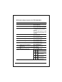
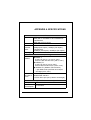
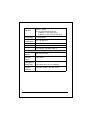
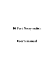
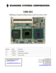
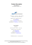
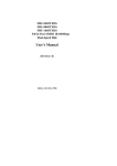
Trademarks Copyright PLANET Technology Corp. 2002. PLANET is a registered trademark of PLANET Technology Corp. All other trademarks belong to their respective owners. Contents in this document are subject to revision without prior notice. FCC Class A Appliance This equipment generates and uses radio frequency energy. If it is not installed and used properly in strict accordance with the manufacturer‘s instructions, it may cause interference to radio and television reception. It has been type-tested and found to comply the specifications in sub-part J of Part 15 of FCC Rules, which are designed to provide reasonable protection against such interference in a residential installation. There is no guarantee that interference will not occur in a particular installation. If this equipment does cause interference to radio or television reception which can be determined by turning the equipment off and on, the user is encouraged to try to correct the interference by one or more of the following measures: Re-orient the receiving antenna Relocate the computing device with respect to the receiver Move the computer away from the deceiver Plug the computer into a different outlet so that compute and receiver are on different electrical circuits. If necessary the user should consult the dealer or an experienced radio or television technician for additional suggestions. CE Mark Warning This is a Class A product. In a domestic environment this product may cause radio interference in which case the user may be required to take adequate measures. Revision The information in this manual is subject to change without notice. User's manual for PLANET SOHOConnect Rack Series Switch Model: FSD-800/1600, FSD-401/801/1601SC & ST Rev: 2.0 (March. 2002) Part No. 2010-000004-001 2 SOHOConnect Rack Series Table of Contents CHAPTER 1 GENERAL INTRODUCTION................................5 CHECKLIST......................................................................................5 INTRODUCTION ...............................................................................5 FEATURES .......................................................................................6 CHAPTER 2 HARDWARE DESCRIPTION ...............................9 2.1 FRONT PANEL ...........................................................................9 2.1.1 FSD-401 ............................................................................9 2.1.3 FSD-800/FSD-801 ..........................................................10 2.1.3 FSD-1600/FSD-1601 ......................................................12 2.2 REAR PANEL ...........................................................................13 2.3 HARDWARE INSTALLATION.....................................................15 CHAPTER 3 CONFIGURATION AND APPLICATION.........17 3.1 THE SWITCH OPERATION ........................................................17 3.2 THE SMART FUNCTION (16-PORT MODEL)...............................20 3.2.1 TP or Fiber-optic selection (for FSD-1601 only) ...........20 3.2.2 Port-based VLAN ............................................................20 3.2.3 Port-Trunking..................................................................21 3.2.4 IP ToS/DS (DiffServ), VLAN Tag Based QoS .................21 3.2.5 Port-based priority..........................................................22 3.3 APPLICATION ..........................................................................22 3.3.1 Basic 100Mbps Server, PCs to 10/100Mbps Switch .......22 3.3.2 Connect to 100Base-FX Switch/Device...........................23 3.3.3 Set up the workgroup and uplink to the backbone (Model: FSD-1600/1601).......................................................................24 3.3.4 Set up Video/Voice Networks (Model: FSD-1600/1601) 25 CHAPTER 4 TROUBLESHOOTING .........................................26 APPENDIX A SPECIFICATIONS ..............................................27 APPENDIX B RJ-45 PIN SPECIFICATION..............................30 FSD-Series User’s Manual 3 4 SOHOConnect Rack Series CHAPTER 1 GENERAL INTRODUCTION Checklist Check the contents of your package for following parts: ♦ The Fast Ethernet Switch ♦ User’s Manual ♦ Power Cord If any of these pieces are missing or damaged, please contact your dealer immediately, if possible, retain the carton including the original packing material, and use them against to repack the product in case there is a need to return it to us for repair. Introduction The 4/8/16-port 10/100Mbsp Ethernet Switch is designed to allow simultaneous transmission of multiple packets via an internal high-speed data channel. This means that it can partition a network more efficiently than bridges or routers in most environments. This Switch is a highly reliable network switch and is the ideal device for bridging Ethernet to Fast Ethernet workgroups or networks. Simple and cost-effective, the Switch complies to IEEE802.3u, IEEE802.3, 100Base-TX, and 10Base-T. Therefore, the Switch will be the fast being recognized as one of the most important building blocks for today networking technology. Choice of 100Base-FX optic-fiber ST/SC interface, the FSD 401/801/1601ST&SC are also ideal to extend the network distance up to 2 kilometers away as a link to your remote backbone. The Switch also provide rack-mounting kits for being installed on 10-inch rack to ease the placement and management effort. FSD-Series User’s Manual 5 Compact in size and designed for Plug and Play installation, the Switch allows the network administrator to simply connect the network and power cables and the switching/bridging functions begin automatically. No hardware or software configurations are required. The front panel of the Switch provides LED indicators for easy recognition of the switch operation status and for troubleshooting. These LED indicators display the power status for the system and link/activity, speed, and full-duplex status for each port. With 4/8/16-port Fast Ethernet Switching designed specifically for connecting workgroup devices and desktops, companies no longer have to invest in expensive and inflexible switches engineered primarily for backbone implementations. Instead, companies can deploy scaleable, affordable switches that increase the aggregate bandwidth of the network by boosting throughput to the workgroups that need it most. Features ♦ ♦ ♦ ♦ ♦ ♦ ♦ ♦ 6 4/8/16-port 10/100base-TX Auto-Negotiation Ethernet Switches One optional 100Base-FX fiber port for extending up to 2km Complies with the IEEE802.3 Ethernet and IEEE802.3u Fast Ethernet standard Features Store-and-Forward architectures with wire-speed filtering and forwarding rates Provide rack-mounting kit for 10-inch Rack Full/Half-Duplex capability on every TX ports, total bandwidth is up to 200Mbps/port Support up to 1K/2K Uni-cast address, Layer 2 address resolution-Self Learning Broadcast storm control SOHOConnect Rack Series ♦ ♦ ♦ ♦ ♦ ♦ ♦ IEEE802.3x compliant full-duplex flow control Back pressure half-duplex flow control Runt and CRC Filtering eliminates erroneous packets to optimize the network bandwidth Provide internal power supply LED indicators for simple diagnostics and management Auto- MDI and MDI-X detect for easily connecting to PC or hub/Switch uplink DIP Switch for smart function (16-port model only) FSD-Series User’s Manual 7 This page intentionally left blank! 8 SOHOConnect Rack Series CHAPTER 2 HARDWARE DESCRIPTION This section describes the hardware features of the Switch. For easier management and control of the Switch, familiarize yourself with its display indicators, and ports. Front panel illustrations in this chapter display the unit LED indicators. Before connecting any network device to the hub, read this chapter carefully. 2.1 Front Panel The unit front panel provides a simple interface monitoring the Switch. It includes a power indicator for each port. 2.1.1 FSD-401 Figure 1. Front Panel of the FSD-401SC/ST LED indicators Printing Power (PWR) Color Description Green This indicator turns on green after the Switch is powered. Remains off with no power Link/ Act Green This indicator green when the port is connected to a either 10Mbps Ethernet or 100Mbs Fast Ethernet station , If the station to which the Switch is connected is powered off, or if there is a problem with the link, the LED will remain off. And the indicator blinking green when the data will be received to all other connected ports. FSD-Series User’s Manual 9 100 Green This indicator green when the port is connected to a 100Mbps Fast Ethernet station. If the station to which the Switch is connected is powered off, a 10Mbps Ethernet station, or if there is a problem with the link, the LED will remain off. FDX Green Lit: Full duplex operation Unlit: Half duplex operation DIP Switch Printing Description FDX (default) The 100Base-FX fiber port of the switch is operating in full-duplex mode. HDX The port is operating in half-duplex mode. )Note: Please check the opposite end is using the same transmit mode before make the connection. 2.1.3 FSD-800/FSD-801 Figure 2. Front Panel of FSD-800 / FSD-801 10 SOHOConnect Rack Series LED indicators Printing Color Power Green (PWR) Link/ Act Green 100 Green FDX/ COL Amber Description This indicator lights green when the Switch is receiving power, otherwise it is off. This indicator green when the port is connected to a either 10Mbps Ethernet or 100Mbs Fast Ethernet station , If the station to which the Switch connected is powered off, or if there is a problem with the link, the LED will remain off. And the indicator blinking green when the data will be received to all other connected ports. This indicator green when the port is connected to a 100Mbps Fast Ethernet station. If the station to which the Switch is connected is powered off, a 10Mbps Ethernet station, or if there is a problem with the link, the LED will remain off. Lit: Full duplex operation Unlit: Half duplex operation Blink: indicates data collisions on the respective Ethernet segment of this port. Whenever a collision is detected, the respective COL indicator will briefly blink. This is normal when the network is busy. DIP Switch (FSD-801) Printing Description FDX (default) The 100Base-FX fiber port of the switch is operating in full-duplex mode. HDX The port is operating in half-duplex mode. )Note: Please check the opposite end is using the same transmit mode before make the connection. FSD-Series User’s Manual 11 2.1.3 FSD-1600/FSD-1601 Figure 3. Front Panel of FSD-1600/ FSD-1601 LED indicators Printing Color Power Green (PWR) Link/ Act Green 100 12 Green Description This indicator lights green when the Switch is receiving power; otherwise, it is off. This indicator green when the port is connected to a either 10Mbps Ethernet or 100Mbs Fast Ethernet station , If the station to which the Switch is connected is powered off, or if there is a problem with the link, the LED will remain off. And the indicator blinking green when the data will be received to all other connected ports. This indicator green when the port is connected to a 100Mbps Fast Ethernet station. If the station to which the Switch is connected is powered off, a 10Mbps Ethernet station, or if there is a problem with the link, the LED will remain off. SOHOConnect Rack Series FDX/ COL Amber Lit: Full duplex operation Unlit: Half duplex operation Blink: indicates data collisions on the respective Ethernet segment of this port. Whenever a collision is detected, the respective COL indicator will briefly blink This is normal when the network is busy. )Note: Port # 16 of FSD-1601 is a shared port. Either Twisted Pair port or Fiber-optic port can operate in one time. 2.2 Rear Panel There is one power socket on the back of the switch, 100~240VAC, 50/60Hz. And one more DIP-switch for FSD-1600 and FSD-1601 for smart function. Figure 1. Rear Panel of the FSD-4/80x Figure 2. Rear Panel of the FSD-1600/1601 FSD-Series User’s Manual 13 DIP Switch (Smart function for FSD-1600/1601) DIP 1 Function Description TP / FX Selection ON: Enable FX OFF: Enable TP 2 Fiber Full/Half duplex Switch ON: Enable Fiber Full Duplex OFF: Enable Fiber Half Duplex 3 VLAN topology type selection ON: 15VLANs (port#1-15) with 1 overlapping port (port#16) topology OFF: 14VLANs (port#1-14) with 2 overlapping port (port#15,16) topology 4 Port Based VLAN ON: Enable VLAN OFF: NO VLAN 5 Port Trunk 0 (port 1,2,3,4) ON: Enable Trunk group 0 OFF: Disable group 0 6 Port Trunk 1 (port 5,6,7,8) ON: Enable Trunk group 1 OFF: Disable group 1 7 Port Trunk 2 (port 9,10,11,12) ON: Enable Trunk group 2 OFF: Disable group 1 8 Port Trunk 3 (port 13,14,15,16) ON: Enable Trunk group 3 OFF: Disable group 3 9 TCP/IP TOS / DS (Diffserv) ON: Enable QoS Based QoS OFF: Turn off the QoS 10 802.1Q VLAN Tag Priority Based ON: Enable Qos OFF: Disable 11&12 Port Based Priority QoS 12 11 Description OF OF Disable F F OF ON Port 1-2 high priority F ports (2 ports) ON OF Port 1-4 high priority F ports (4 ports) ON ON Port 1-8 high priority ports (8 ports) 14 SOHOConnect Rack Series )Note: 1. For fiber-optic connection, please check the opposite end is using the same transmit mode before make the connection. 2. Port#16 of the switch is shared with 100Base-FX port. Make sure either Fiber-optic or twisted pair port is being connected. 3. For more information about the Smart function, please refer to Chapter 3. 4. All the DIP is in OFF position by default! 2.3 Hardware Installation 1. Place the Switch on a smooth surface 2. Connect the output cord of power supply to the AC inlet. 3. Connect hub or PC to one port of the Switch using Category 3/4/5 UTP/STP cabling. 4. Connect another hub or PC to the other port of Switch by following the same process as described in Step 3. Notice: Cable distance for the Switch The cable distance between the Switch and hub / PC should not exceed 100 meter. The fiber-optic should not exceed 412 meters in Half-duplex mode and 2 kilometers for Full-duplex mode Make sure the wiring is correct It can be used Category 3/4/5 cable in 10Mbps operation. To reliably operate your network at 100Mbps, you must use an Unshielded Twisted-Pair (UTP) Category 5 cable, or better Data Grade cabling. While a Category 3 or 4 cable may initially seem to work, it will soon cause data loss. The fiber-optic cable should be a multi-mode fiber cable with 62.5/125µm or 50/125µm in specification. FSD-Series User’s Manual 15 You can find the information from the printing of the cable. If you are not familiar with it, please consult your local dealers for the information. Power System The Switch accepts AC input with 100~240V AC, 50/60Hz. To prevent from data loss or network downtime, consider install an UPS (Un-interrupt Power Supply) for the Switch. And in some area, a surge suppression device also can help to prevent from the Switch being damaged by un-regulated surge or current to it. All kinds of hub / PC can connect to switch by using straight-through wires. The Switch also supports auto MDI detection. This means you can direct connect any port of the Switch to another MDI-X devices with a straight wire. 16 SOHOConnect Rack Series CHAPTER 3 CONFIGURATION AND APPLICATION This chapter shows you how the Switch works, and how to install the Switch and also to configure the smart functions provided in the 16-port model. 3.1 The Switch Operation Address Table The Switch is implemented with an address table. This address table composed of many entries. Each entry is used to store the address information of some node in network, including MAC address, port no, etc. The information comes from the learning process of Ethernet Switch. Learning When one packet comes in from any port. The Ethernet Switch will record the source address, port no. and the other related information in address table. These information will be used to decide either forwarding or filtering for future packets. FSD-Series User’s Manual 17 Forwarding & Filtering When one packet comes from some port of the Ethernet Switch, it will also check the destination address besides the source address learning. The Ethernet Switch will lookup the address table for the destination address. If not found, this packet will be forwarded to all the other ports except the port which this packet comes in. And these ports will transmit this packet to the network it connected. If found, and the destination address is located at different port from this packet comes in, the Ethernet Switch will forward this packet to the port where this destination address is located according to the information from address table. But, if the destination address is located at the same port with this packet comes in, when this packet will be filtered. Thereby increasing the network throughput and availability Store-and-Forward Store-and-Forward is one type of packet-forwarding techniques. A Store-and-Forward Ethernet Switch stores the incoming frame in an internal buffer, do the complete error checking before transmission. Therefore, no error packets occurrence, it is the best choice when a network needs efficiency and stability. The Switch scans the destination address from the packet header, searches the routing table provided for the incoming port and forwards the packet, only if required. The fast forwarding makes the switch attractive for connecting servers directly to the network, thereby increasing throughput and availability. However, the switch is most commonly used to segment existing hubs, which nearly always improves overall performance. A Ethernet Switch can be easily configured in any Ethernet network environment to significantly boost bandwidth using conventional cabling and adapters. 18 SOHOConnect Rack Series Due to the learning function of the Ethernet switch, the source address and corresponding port number of each incoming and outgoing packet are stored in a routing table. This information is subsequently used to filter packets whose destination address is on the same segment as the source address. This confines network traffic to its respective domain, reducing the overall load on the network. The Switch performs “Store-and-forward” therefore, no error packets occur. More reliably, it reduces the re-transmission rate. No packet loss will occur. Auto-Negotiation The STP ports on the Switch have built-in "Auto-Negotiation." This technology automatically sets the best possible bandwidth when a connection is established with another network device (usually at Power On or Reset). This is done by detect the modes and speeds at the second of both device is connected and capable of. Both 10Base-T and 100Base-TX devices can connect with the 100Base-TX port in either Half- or Full-Duplex mode. If attached device is: 100Base-TX port will set to: 10Mbps, no auto-negotiation 10Mbps, with auto-negotiation 10Mbps 100Mbps, no auto-negotiation 100Mbps, with auto-negotiation 100Mbps FSD-Series User’s Manual 10/20Mbps (10Base-T/Full-Duplex) 100/200Mbps (100Base-TX/Full-Duplex) 19 3.2 The Smart Function (16-port model) The FSD-1600 and FSD-1601 is with one DIP switch on the rear of the switch, these ON/OFF switches provides the functions as below: Twisted Pair or Fiber-optic selection Port based VLAN Port Trunking ToS/ QoS selection Priority Setup They are all in OFF position by default! 3.2.1 TP or Fiber-optic selection (for FSD-1601 only) Related DIP: 1, 2 Default meaning: Port#16 runs in Twisted pair, Auto-Negotiation. DIP 1: Turns on will force the fiber-optic port enabled. )Note: Please do not turn on if you are using FSD-1600. DIP 2: Turns on will force the 100Base-FX fiber-optic port runs in Full-duplex mode. 3.2.2 Port-based VLAN Related DIP: 3, 4 Default meaning: No VLAN setting. VLAN can be used to separate ports into different groups in the same switch. This will secure port from being accessed by other ports on the switch. DIP 4: Turns on will enable the port-based VLAN capability DIP 3: The two positions represent two different VLAN choices: 20 SOHOConnect Rack Series OFF: There are 14 VLANs. Port 1 to Port 14 can communicate with Port 15, and Port 16 where 1 to 14 cannot see each other. ON: There are 15 VLANs. Port 1 to Port 15 cannot see each other but they all can retrieve data from port 16. i.e. members of VLAN 1 are 1 & 16, VLAN 2 are 2 & 16, VLAN 3 are 3 & 16, etc. 3.2.3 Port-Trunking Related DIP: 5, 6, 7, 8 Default meaning: No port-trunking. Port trunks will four times the bandwidth (800Mbps) while connecting with another switches that also with port trunk capability. Up to four groups where each group with 4 ports is allowed. DIP 5: Turns on to enable trunk 0, from port 1 to port 4. DIP 6: Turns on to enable trunk 1, from port 5 to port 8. DIP 7: Turns on to enable trunk 2, from port 9 to port 12. DIP 8: Turns on to enable trunk 3, from port 13 to port 16. )Note: Turn on the Trunk will also disable VLAN capability. 3.2.4 IP ToS/DS (DiffServ), VLAN Tag Based QoS Related DIP: 9, 10 Default meaning: No priority-packet detection. The Switch will store each incoming packets and check the tag field to determine the priority, high or low. Then follow the priority to forward to the destination. The Switch supports two types of detection. VLAN Tag-based detection (Layer 2) ToS/DS (DiffServ) detection (IP Layer 3) DIP 9: Turns on for IP ToS/DS QoS. FSD-Series User’s Manual 21 DIP 10: Turns on for VLAN tag priority QoS. )Note: The connected end-nodes (PCs, Routers) should also support VLAN priority or ToS priority. Normally, these functions could turn off by default. Check the user’s guide of your networked device for this capability. 3.2.5 Port-based priority Related DIP: 11, 12 Default meaning: No hardware port priority. If your end-nodes do not support priority, and you would like to preserve more bandwidth for those network users, port-based priority will direct set the related port to high priority. DIP 11 ON DIP 12 Description Port 1 and Port 2 are high priority ports OFF OFF ON Port 1~ 4 are high priority ports ON ON Port 1 ~8 are high priority ports )Note: FSD-1600/1601 only support dual priority, this means the priority only will be HIGH or LOW no matter which port you connected to. )Note: Priority support can co-work with VLAN. 3.3 Application 3.3.1 Basic 100Mbps Server, PCs to 10/100Mbps Switch Plug one end of the Category 5 UTP Cable into any one port of the Switch, and the other end of this cable into the RJ-45 of Fast Ethernet Adapter in the server or PC. The cable length between these 2 connecting points should not exceed 100 meters. 22 SOHOConnect Rack Series Figure 3. 10/100Mbps File server to Switch Connection 3.3.2 Connect to 100Base-FX Switch/Device (Model: FSD-4/8/1601) Plug the pair the fiber-cable to the Switch’s fiber-optic port, secure the fiber-optic connector. Connect to other end to the fiber-optic port of the device like repeater hub, switch or workstations. Be noted for the duplex mode. For Hub, only Half-Duplex mode can be selected, at the mean time, the cable distance cannot exceed 412 meters. For Switch or end-node that works on full-duplex mode, the maximum distance cannot exceed 2 kilometers. The pair of the connectors must be crossed, ie. TX/RX port of the Switch should connect to RX/TX Port of the device in other end. Consult your local dealer for more information about fiber-optic wires, connector type or network distances. FSD-Series User’s Manual 23 Figure 4. Fiber-cable Switch to Switch Connection 3.3.3 Set up the workgroup and uplink to the backbone (Model: FSD-1600/1601) Figure 5. Connection with VLAN enable Turn on the DIP 4, the FSD-1600 soon separate the fourteen ports (Port 1 to Port 14) into different group, then you can install two file servers to port 15, port 16, those fourteen users shall not see each other where they can freely access the information from the two file server. Or, port 15 is connect to your local server and port 16 up connect to your networks 24 SOHOConnect Rack Series backbone, either 100 meters (FSD-1600) or 2 kilometers away (FSD-1601, both DIP 1 & 2 in ON position) 3.3.4 Set up FSD-1600/1601) Video/Voice Networks (Model: Some networks could have a devices like Video or Voice device like Internet Telephony Gateway, the support of priority may help you to make your voice or video in higher position to get the precious networks bandwidth, for example to the Intermet. If your Voice Gateway support ToS, you may direct turn on the DIP 9 to get the higher priority, or if your device or network nodes do not support you can turn on DIP 11 or DIP 12 to have the hardware priority, Figure 6. 3 Voice Gateway to Switch Connection FSD-Series User’s Manual 25 CHAPTER 4 TROUBLESHOOTING This chapter contains information to help you solve problems. If the Switch is not functioning properly, make sure the Switch was set up according to instructions in this manual. The Link LED is not Lit Solution: Make sure the switch configuration is consistent with the connecting device Check the cable connections. Performance is bad Solution: Check the full duplex status of the Ethernet Switch. If the Ethernet Switch is set to full duplex and the partner is set to half duplex, then the performance will be poor. Some stations can not talk to other stations located on the other port Solution: The address table may contain older information than of the address table of that node. Please power down to refresh the address information. 26 SOHOConnect Rack Series This page intentionally left blank! FSD-Series User’s Manual 27 APPENDIX A SPECIFICATIONS Standards: Protocol: Data Transfer Rate: Topology: General (Ethernet) IEEE 802.3 10Base-T Ethernet IEEE 802.3u 100 Base-TX and 100Base-FX Fast Ethernet IEEE 802.3x Flow control CSMA/CD Ethernet: 10Mbps(half duplex) / 20Mbps (full duplex) Fast Ethernet: 100Mbps (half duplex) / 200Mbps (full duplex) Star General (Cabling) Network Cables: ◆10Base-T: 2-pair UTP Cat. 3,4, 5 (100 m, max.) EIA/TIA- 568 100-ohm STP (100 m, max.) ◆100Base-TX: 2-pair UTP Cat. 5 (100 m, max.) EIA/TIA-568 100-ohm STP (100 m, max.) ◆100Base-FX: (Models: FSD-4/8/1601) 1-pair Multi-mode optic fiber 62.5/125µm, 50/125µm(2 km, max.) Number of Ports: 4/8/16-STP ports Models:FSD-4/8/1601 1-ST/SC fiber-optic port (1300nm wavelength) Hardware Physical /Environmental Specification AC inputs 100~240VAC, 50~60Hz Power Consumption 15~25 watts 28 SOHOConnect Rack Series LED Indication Operating Temperature Storage Temperature System : Power Port: 3 LED Indicators per port (LINK/ACT, 100, FDX/ COL) (LINK/ACT, 100, FDX for FSD-401) 0 ~ 50 degree C -20 ~ 70 degree C Humidity 10% ~ 90% non-condensing Dimensions 220 x 135 x 44 mm (W x D x H) EMI FCC Class A, CE Mark Class A Performance Transmission Method Filtering Address Table Packet Filtering/Forw arding Rate MAC Address Learning Store-and-forward 1/2K entries 14,880pps per port (for 10Mbps) 148,800pps per port (for 100Mbps) Automatic update / Max age: fixed FSD-Series User’s Manual 29 APPENDIX B RJ-45 PIN SPECIFICATION When connecting your FSD-series 10/100Mbps Ethernet Switch to another switch, a bridge or a hub, a modified crossover cable is not necessary. Each port of the Switch is auto-MDI detection. That means you can direct connect the Switch to any Ethernet devices with a Category 5, UTP straight wire. However, the following diagram and tables also show the standard RJ-45 receptacle/connector and their pin assignments for the switch-to-network adapter card connection, and the straight / crossover cable for the Switch-to-switch/hub/bridge connection. RJ-45 Connector pin assignment Contact 1 2 3 4, 5 6 7, 8 Media Direct Media Direct Interface Signal Interface -Cross TX + (transmit) Rx + (receive) TX - (transmit) Rx - (receive) Rx + (receive) TX + (transmit) Not used Rx - (receive) TX - (transmit) Not used The standard cable, RJ-45 pin assignment The standard RJ-45 receptacle/connector 30 SOHOConnect Rack Series 2010-000004-001