1
TA 3050
10 Port ASI / IP Multiplexer and
Media Router
USER GUIDE
www.adtecdigital.com
Table of Contents
Product Overview.......................................................................................................................................................................1
Introduction - About Digital Turn Around........................................................................................................................1
Applications.............................................................................................................................................................1
Benefits of an Adtec Digital Turn Around Router....................................................................................................1
About Your Purchase.....................................................................................................................................................2
Hardware Specification & Requirements.................................................................................................................3
Front Panel.....................................................................................................................................................................3
Front Panel Features:..............................................................................................................................................3
Back Panel..............................................................................................................................................................3
Electrical Device Compliance Notices............................................................................................................................6
Safety Warnings and Cautions................................................................................................................................6
Lithium Battery Safety Statement............................................................................................................................6
Compliance Notices................................................................................................................................................7
Getting Started............................................................................................................................................................................9
Installation......................................................................................................................................................................9
Tour the DTA3050.................................................................................................................................................10
Front Panel Layout................................................................................................................................................10
Back Panel............................................................................................................................................................12
Connectivity Features............................................................................................................................................12
LED Status Indicators...................................................................................................................................................13
System Indicators..................................................................................................................................................13
Output LEDs..........................................................................................................................................................13
Input LEDs.............................................................................................................................................................14
Setting IP Parameters..................................................................................................................................................15
Setting IP Parameters from the Front Panel.........................................................................................................15
Setting IP Parameters via a terminal (Telnet) session..........................................................................................15
Front Panel Programming and Control.........................................................................................................................16
Modes....................................................................................................................................................................16
Front Panel Menu Flows.......................................................................................................................................18
Pre-programmed Key Sequences.........................................................................................................................18
Front-Panel-Only Control Options.........................................................................................................................19
Communications...........................................................................................................................................................20
LAN.......................................................................................................................................................................20
RS-232..................................................................................................................................................................20
Ethernet.................................................................................................................................................................20
User Interface............................................................................................................................................................................23
Port and Table Mode....................................................................................................................................................23
Port Mode..............................................................................................................................................................23
Table Mode...........................................................................................................................................................23
Using the GUI Interface................................................................................................................................................24
Introduction............................................................................................................................................................24
Signing in to the GUI.............................................................................................................................................25
System Screen......................................................................................................................................................26
Host Screen...........................................................................................................................................................27
Inputs Screen........................................................................................................................................................29
Mappings Screen..................................................................................................................................................31
Outputs Screen.....................................................................................................................................................33
Tables Screen.......................................................................................................................................................35
Conditional Access Screen...................................................................................................................................42
IP Destinations Screen..........................................................................................................................................45
Multi-Protocol Encapsulation Screen....................................................................................................................49
Redundancy Screen..............................................................................................................................................51
Encoder Redundancy............................................................................................................................................52
Multiplexer Redundancy........................................................................................................................................57
Logs Screen..........................................................................................................................................................59
Updates Screen.....................................................................................................................................................60
Modulation Targets Reference..............................................................................................................................62
Manual Upgrades..................................................................................................................................................63
i
Table of Contents
Operations.................................................................................................................................................................................65
Manual PID Injection - Overview .................................................................................................................................65
Requirements........................................................................................................................................................65
Using XCrypt with the DTA3050............................................................................................................................68
Appendix....................................................................................................................................................................................71
Contacting Customer Support......................................................................................................................................71
Telephone and Email Support...............................................................................................................................71
Information needed for Support.............................................................................................................................71
Advanced Support Plans.......................................................................................................................................72
Troubleshooting Guide: DTA3050.........................................................................................................................73
Technical Specifications for the Adtec DTA30-50-HW3 Digital Turn Around Media Router ......................................74
Inputs.....................................................................................................................................................................74
Outputs..................................................................................................................................................................76
DTA Management.................................................................................................................................................79
Platform.................................................................................................................................................................79
GNU General Public License........................................................................................................................................80
Preamble...............................................................................................................................................................80
GNU GENERAL PUBLIC LICENSE TERMS AND CONDITIONS FOR COPYING, DISTRIBUTION AND
MODIFICATION.............................................................................................................................................80
How to Apply These Terms to Your New Programs..............................................................................................82
ii
Product Overview
Introduction - About Digital Turn Around
Digital Turn Around (DTA) is a commonly required function for Terrestrial, Cable, and IPTV distribution. Adtec's
DTA-3050-HW3 provides the means of receiving up to ten physical Single (SPTS) or Multiple (MPTS) Program Transport
Streams and re-multiplexing, table processing, ciphering and routing to a single triplex-mirrored Asynchronous Serial Interface
(ASI) and or Gigabit Ethernet (GIGE) interface.
Applications
• Telco IPTV / Broadband IPTV: Cost-effective and reliable delivery of video, audio and data services to an unlimited
number of consumer set top boxes or PC/MAC clients on an IP network.
• Satellite Digital TV: Aggregate video, audio and data services, process services, inject tables, encrypt and pass
them via ASI or IP to modulators supporting traditional DVBS and the emerging DVBS2 or other satellite distribution
method.
• Terrestrial Digital TV: Aggregate video, audio and data services, process services, inject tables, encrypt them and
pass them via ASI or IP to modulators supporting ATSC, DVBT, DVBH, DMB, or other terrestrial distribution method.
• Cable Digital TV: Aggregate video, audio and data services, process services, inject tables, encrypt them and pass
them via ASI or IP to modulators supporting traditional DVBC (Annex A, B, C) distribution method.
• IP over MPEG 2 Transport: Delivery of IP data services to set top boxes or computers over MPEG-2 transport using
IP encapsulation.
Benefits of an Adtec Digital Turn Around Router
• Conditional Access: The DTA-3050 provides DVB-CSA encryption and AES conditional access encrypt and decrypt
capabilities. DVB-CSA encryption is available as a Simulcrypt based interfacescompatible with most major DVB-CSA
CAS vendors. AES decryption and encryption include support for Verimatrix VCAS for residential set top and
computer-based decryption.
• Aggregation of ASI, SMPTE-310, or IP based SPTS or MPTS services: The DTA-3050 provides ten ASI input
ports enabling it to aggregate locally encoded SPTS or re-muxed MPTS from encoders, receivers, video servers or
other devices providing MPEG 2 Transport via ASI or IP.
• IPTV: Gigabit Ethernet distribution of digital television services includes MPTS, SPTS over UDP, RTP for Set Top or
computer decoding and MPTS over UDP or RTP for bundled distribution (Digital Simulcast).
• ASI: An optional 3 port mirrored ASI output interface provides integration with traditional distribution methods
including Cable, Satellite, and Terrestrial.
• SMPTE-310: An optional 2 port mirrored SMPTE-310 output interface provides integration with ATSC distribution.
• Flexible Configuration & Control: Controlling and configuring the DTA-3050 is easy. Whether using the integrated
front panel keypad and LCD, Terminal or remote Web page interface, they respond rapidly and reliably to the desires
of the operator.
• Dynamic EIT Injection: Adtec's free EIT scheduler service DTVGuide comes standard with all DTA products.
1
Product Overview
About Your Purchase
Thank you for purchasing Adtec’s DTA-3050 Digital Media Multiplexer/Router! The DTA-3050 is a revolutionary ASI MPEG 2
Transport Multiplexer and Digital Media Router designed for DVB-ASI distribution applications.
The DTA-3050 represents a revolutionary enhancement for real-time multiplexing applications that require high reliability and
broadcast quality without requiring a large budget. The DTA-3050 is capable of providing aggregation of up to ten (10) Single
Program Transport Streams (SPTS) or Multiple Program Transport Streams (MPTS) over copper ASI MPEG 2 inputs and
producing a Multiple Program Transport Stream (MPTS) output over ASI, SMPTE 310M, or GigE. The DVB-ASI output is
targeted to cable and digital satellite television and digital television (DTV) applications over 8VSB (19.39 Mbps) using SMPTE
310M.
All Adtec DTA-3050 Multiplexer/Routers provide table support for MPEG-2 PSI, DVB SI, ATSC PSIP, and DigiCipher II tables.
Additionally, they support encapsulation of IP packets via Multi-Protocol Encapsulation (MPE) as defined by ISO/IEC 13818-6
and conditional access: support for the Common Scrambling Algorithm (CSA) using the Ethernet SimulCrypt Interface and
Advanced Encryption Standard (AES) with RSA public/private key distribution.
Key features of the Multiplexer/Router include:
• Highly-Reliable Embedded Design based on Linux Operating System
• 10 copper ASI Inputs
• Copper ASI Outputs (triple-mirrored outputs)
• SMPTE 310M (dual-mirrored outputs)
• PCR Restamping
• PID Remapping
• LCD/Keypad display for front panel management and control
• 13818-6 Multiprotocol Encapsulation of Multicast and Unicast IP Data (Optional)
• SPTS and MPTS to MPTS aggregation
• DCII Input to DVB feeds
• PSIP Table Generation
• Conditional Access
♦ Built in DVB Common Scrambler Algorithm (CSA) (Optional)
♦ AES encryption for Verimatrix (Optional)
• Transport Stream over IP
Notices and Disclaimers
(c) 2011 Adtec Digital. All rights reserved. This document may not, in whole or in part, be copied, photocopied, reproduced and
translated, or reduced to any electronic medium or machine-readable form without prior consent in writing from Adtec Digital.
Trademarks: DTA305x is a trademark of Adtec Digital. Dolby and the double-D symbol are registered trademarks of Dolby
Laboratories. Other product and company names may be trademarks or registered trademarks of their respective companies.
The information in this document is subject to change without notice.
Product Overview
2
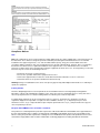
Hardware Specification & Requirements
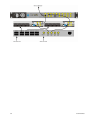
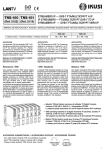
Front Panel
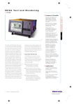
Front Panel
Front Panel Features:
• 8 Button Tactile Raised keypad:
♦ Mode, Select, Enter, Escape, Up, Down,Left, Right
• Blue Translucent LCD
♦ 20 character by 2 row
• Front Panel Host LED’s
♦ Power, Alarm, Link, Busy, MPE
• Front Panel LEDs
♦ In : 1 - 10 ASI
♦ Out : Alarm, ASI, SMPTE 310, CA, GigE
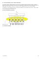
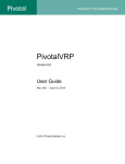
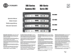
Back Panel
Back Panel Image:
Physical Dimensions
Dimension
Value
Heighth
1.75 inches (44.5mm)
Width
19 inches (483mm)
Depth
16 inches (406mm)
Footprint
1 rack unit
Weight
13 pounds
Power Requirements
• 70-240 VAC switching power supply
• 50/60 Hertz
• Rated at 94 Watts; return nominal usage 20 Watts
ASI Inputs
• ASI x 10 (BNC)
• 188 or 204 Byte mode
• SPTS or MPTS
• 210 Mbps per input
• 256 PIDs per input
• Input Modes
♦ Auto (Remap all services)
♦ Manual (Add/Drop/Remap PID/Services)
♦ Pass (Pass all services as-is)
♦ MHP Injector
♦ SI Injector
3
Product Overview
Outputs
• Gigabit Ethernet
♦ SPTS over UDP or RTP
♦ MPTS over UDP or RTP
♦ 210 Mbs
♦ Very low jitter
• ASI (model is DTA 3050)
♦ Mirrored (BNC x 3)
♦ Byte or Burst Mode
◊ 54 Mbs Byte
◊ 210 Mbs Burst
♦ Jitter less than 150 (nS)
• SMPTE-310 (model is DTA 3051)
♦ Mirrored (BNC x 2)
♦ Byte Mode only
♦ 19.39 Mbs fixed
♦ SMPTE-310 option includes ASI
Table Processing
• No Tables
• MPEG Tables
♦ PAT
♦ CAT (if CA is enabled)
♦ PMT
• DVB Tables (Add/Drop/Remap DVB Services)
♦ NIT
♦ SDT
♦ TDT/TOT
♦ EIT
• ATSC Tables (Add/Drop/Remap ATSC Services)
♦ VCT (Cable or Terrestrial)
♦ MGT
♦ STT
♦ RRT
♦ EIT (1-4)
• DCII Tables (Add/Drop/Remap Digicypher services to DVB or ATSC)
Conditional Access Encryption
• DVB-Common Scrambling Algorithm (CSA)
• DVB Simulcrypt TS 103 197 v 1.2.1 and SCTE
• OpenCAS TM DVS-278 compliant
• FIPS 140-2 hardware based random number generator (RNG)
• Advanced Encryption Standard (AES)
♦ IP Set Top and Computer compatibility
• Approved 3rd Party CA Vendors include:
♦ CSA:
◊ Irdeto
◊ Conax
◊ EuroCAS
◊ KeyFly
◊ Xcrypt
♦ AES:
◊ Verimatrix
Host Platform
• PowerPC
• Adtec optimized Linux Kernel
• 10/100 Ethernet RJ-45 (Eth 0)
• 10/100/1000 Ethernet RJ-45 (Eth 1)
• Serial Port (RJ-48)
• USB 2.0 (2)
Product Overview
4
• N.C. / N.O. Tally Interface
• XML Configuration
• HTTP, FTP, Telnet, IP Logging, DHCP,
♦ (XCP Adtec encrypted layer 3 protocol)
Environmental Requirements Operational
Factor
Conditions
Temperature
0 degrees C to +50 degrees C (+32 degrees F to +122 degrees F )
Humidity
5% to 95% (non-condensing)
Cooling
Convection Cooling/Free Airflow
Handling/Mounting
Fixed Use Only
Storage
Factor
Conditions
Temperature
-30 degrees C to +65 degrees C (-22 degrees F to +149 degrees F)
Humidity
5% to 95% (non-condensing)
Specifications Legal Disclaimer
Note: Specifications subject to change without written notice. Copyright 2008-2010 Adtec Digital. Product and company
names may be trademarks or registered trademarks of their respective companies.
5
Product Overview
Intentionally Left Blank
Electrical Device Compliance Notices
Safety Warnings and Cautions
For your safety and the proper operation of the device:
• This unit must be installed and serviced by suitably qualified personnel only.
• Disconnect all power before servicing the unit.
• Do not expose this device to rain or other moisture. Clean only with a dry cloth.
• If not installed in an equipment rack, install the product securely on a stable surface.
• Install the product in a protected location where no on can step or trip over the supply cord, and where the supply
cord will not be damaged.
• If a system is installed in a closed or multi-unit rack assembly, the operating ambient temperature of the rack
environment may be greater than the room ambient temperature.
• Consideration should be given to installing the unit in an environment compatible with the maximum recommended
ambient temperature of 50 degrees Celcius (122 degrees Fahrenheit).
• Install the unit in a rack so that the amount of airflow required for safe operation is not compromised.
♦ The recommended clearance on the top and sides of the unit is at least ½ “ (one half inch/one centimeter).
• Mounting of the unit in a rack should be such that no hazardous condition is achieved due to uneven mechanical
loading.
• Use only a grounded electrical outlet when connecting the unit to a power source.
• Reliable earth grounding of rack-mount equipment should be maintained.
♦ Particular attention should be given to supply connection other than direct connections to the branch circuit
(e.g., use of power strips).
Lithium Battery Safety Statement
Product Overview
6
Compliance Notices
FCC:
Note: This equipment has been tested and found to comply with the limits for a Class B digital device, pursuant to Part 15 of
the FCC Rules. These limits are designed to provide reasonable protection against harmful interference in a residential
installation. This equipment generates, uses and can radiate radio frequency energy and, if not installed and used in
accordance with the instructions, may cause harmful interference to radio communications. However, there is no guarantee
that interference will not occur in a particular installation. If this equipment does cause harmful interference to radio or
television reception, which can be determined by turning the equipment off and on, the user is encouraged to try to correct the
interference by one or more of the following measures:
• Reorient or relocate the receiving antenna.
• Increase the separation between the equipment and receiver.
• Connect the equipment into an outlet on a circuit different from that to which the receiver is connected.
• Consult the dealer or an experienced radio/TV technician for help.
Warning: Changes or modifications to this device not expressly approved by Adtec Digital could void the user’s authority to
operate the equipment.
Industry Canada:
This Class B digital apparatus meets all requirements of the Canadian Interference Causing Equipment Regulations.
Operation is subject to the following two conditions:(1) this device may not cause harmful interference, and (2) this device
must accept any interference received, including interference that may cause undesired operation.
Cet appareillage numérique de la classe B répond à toutes les exigences de l'interférence canadienne causant des
règlements d'équipement. L'opération est sujette aux deux conditions suivantes: (1) ce dispositif peut ne pas causer
l'interférence nocive, et (2) ce dispositif doit accepter n'importe quelle interférence reçue, y compris l'interférence qui peut
causer l'opération peu désirée.
European Union EMC Directive conformance statement
This product is in conformity with the protection requirements of EU Council Directive 2004/108/EC on the approximation of
the laws of the Member States relating to electromagnetic compatibility. Adtec Digital cannot accept responsibility for any
failure to satisfy the protection requirements resulting from a user modification of the product. This product has been tested
and found to comply with the limits for Class B Information Technology Equipment according to CISPR 22 / EN 55022.
7
Product Overview
Getting Started
Installation
The DTA-3050 can be installed and made operational in minutes.
1. First, the unit must be installed into a one-rack unit (1U) 19" rack slot, or any secure space where it cannot be easily
moved.
2. Power should be applied to the unit and configured with a valid IP address, subnet mask, and default gateway via the
front panel via the LCD/Keypad for details on setting the IP parameters via the front panel refer to the procedures in
this section.
3. Once the IP parameters have been configured, configuration may take place via the front panel or over the Local
Area Network via a Web browser.
4. Select the output type: ASI (default) or SMTPE 310M.
♦ If using IP only, please select ASI.
♦ When setting the unit up for ASI, a rate must be assigned to the output port before it should be connected to
a modulating device.
5. From a PC connected to a LAN, start a Web browser and in the URL box type the IP address configured.
♦ Note, if no IP address has been configured, the default IP address can be used (192.168.10.48).
9
Getting Started
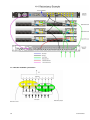
Tour the DTA3050
Front Panel Layout
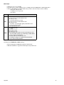
Features and Controls:
Item
Arrow buttons
Function
move cursor on the LCD
System Programming Action Buttons
Mode programming button
selects a menu for configuring the unit's operations; 13 available plus 3
informational "read only" menus
Select programming button
chooses a command or field for the router to execute
Enter programming button
confirms/stores a command and/or data for the router to execute
Escape programming button
exits a field or moves up to the next menu level
LCD display
shows selections available or selected for directly programming the router
Getting Started
10
Item
Function
System Status LED Indicator Cluster
Power LED indicator
indicates if power is available to the unit; see LED Indicators for more
information
Alarm LED indicator
indicates if a system alarm is in force
Link LED indicator
indicates if the unit is linked into a network; see LED Indicators for more
information
Busy LED indicator
indicates if the unit is receiving or sending traffic; see LED Indicators for more
information
MPE LED indicator
indicates if multiprotocol encapsualtion is enabled; see LED Indicators for
more information
Input Status LED Indicators
ASI Input LEDs (10)
indicates status/function on each of the ten ASI ports; see LED Indicators for
more information
Output Status LED Indicators
Output Alarm LED
indicates if an Output alarm is in force
Output ASI Status LED
indicates if output is occuring in this mode, and of what level; see LED
Indicators for more information
Output SMPTE 310 Status LED
indicates if output is occuring in this mode, and of what level; see LED
Indicators for more information
Output CA Status LED
indicates if Conditional Access is enabled (indicates on/off)
Output GigE Status LED
not currently used; no functionality. See GigE Indicator on the back panel,
described below.
LCD display
20-line liquid-crystal display for direct programming of the unit
11
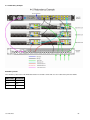
Getting Started
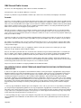
Back Panel
Illustration:
Connectivity Features
Connection
Purpose
Power
standard 12V A/C electrical power connection
GigE
used for IP Egress
Terminal Interface
used to communicate with a PC for serial communications
Fast Ethernet Interface
management of the DTA-Control GUI
Serial Port
used to communicate with redundancy switch
USB 2.0 Interface (2)
for future use (not currently supported in documentation)
ASI Inputs (10)
Asynchronous Serial Inputs (receive programming)
ASI Redundancy Inputs (2)
used to link 2 Muxers (DTA3050's) in tandem; one as primary, one as backup
SMPTE Redundancy Input
used to link 2 Muxers (DTA3050's) in tandem; one as primary, one as backup
Redundancy Tally
used to hookup an external alarm device
ASI Outputs (3)
triple-mirrored ASI Outputs
the first two connectors are used for redundant set-ups
SMPTE 310 Outputs (2)
mirrored SMPTE Output
the first connector is used for redundant set-ups
Getting Started
12
LED Status Indicators
System Indicators
Host Alarm LED- located next to the blue LCD display area.
LED Color
Status
Red
Major Alarm
Yellow
Minor Alarm
Green
No Alarms
Power LED- located next to the blue LCD display area.
LED Color
Status
Green
Power to unit
Unlit
No power to unit
Link LED- located next to the blue LCD display area
LED Color
Status
Green
Link to unit
Unlit
No link to unit
Busy LED- located next to the blue LCD display area
LED Color
Status
Yellow-blinking
Traffic on unit
Unlit
No traffic on unit
MPE LCD- located next to the blue LCD display area (multiprotocol encapsulation)
LED Color
Status
Clear
No MPE data
Yellow
Enabled; no traffic
Green
Enabled; active traffic
Output LEDs
Output Alarm LED - located in "Out" indicator group at left of front panel
LED Color
Status
Red
major alarm until cleared or resolved
Yellow
Minor alarm (until cleared or resolved)
Green
OK- normal operation
13
Getting Started
Output ASI LED- located in "Out" indicator group at left of front panel (Asynchronous Serial Interface)
LED Color
Status
Red
no egress; overflow
Yellow
Outputting Fills (only when 100%; do not flash green and yellow)
Green
Outputting data
Flashing Green
when unit is configured as the back-up
Output SMPTE 310M LED- located in "Out" indicator group at left of front panel
LED Color
Status
Red
no egress; overflow
Yellow
Outputting fills
Green
Outputting data
Clear
not configured
Output CA LED - located in "Out" indicator group at left of front panel (Conditional Access)
LED Color
Status
Yellow
sharing Conditional Access keys
Green
Conditional Access enabled
Unlit
Not enabled
Output GigE LED
On the rear panel, a functional GigE indicator is found. See Rear Panel
Connections in the "Tour the Box" section for a full description.
Although there is an LED on the panel, it is non-functional.
Input LEDs
ASI Inputs 1-10
LED Color
Status
Red
no sync/no tables
Yellow
port enabled, but no programs are mapped to output
Green
OK- normal operation
Green-flashing
port is a backup in a redundant pair
Getting Started
14
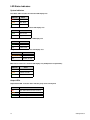
Setting IP Parameters
The IP Parameters for the unit can be set from either the Front Panel or through a terminal session. Setting it via the Front
Panel is easiest, but both methods are described in this topic.
Setting IP Parameters from the Front Panel
The IP address for the unit can be configured through the front panel by following this procedure:
Step
Action
1
Press "Mode" twice, 'eth0 IP Address' will display in the LCD.
2
Press "Select"; the cursor will flash.
3
Press the "Right" arrow key to move through the IP Address fields; press the "Up" and "Down" arrow keys to
change the values in those fields.
4
Press "Enter" when all values have been changed.
5
Press the "Up" arrow to display 'eth0 IP Mask' on the LCD.
6
Press "Select"; the cursor will flash.
7
Press the "Right" arrow key to move through the the IP Address fields; press the "Up" and "Down" arrow keys to
change the values in those fields.
8
Press "Enter" when all values have been changed.
9
Repeat Steps 1-8 to set the eth1 parameters.
10
Press the "Up" arrow to display 'Default Gateway' on the LCD.
'Default Gateway' is the IP Address of your Default Gateway.
11
Press "Select"; the cursor will flash.
12
Press the "Right" arrow key to move through the the IP Address fields; press the "Up" and "Down" arrow keys to
change the values in those fields.
13
Press "Enter" when all values have been changed.
14
Press "Escape" until the top menu appears again.
Setting IP Parameters via a terminal (Telnet) session
To set the IP Address via a terminal Telnet session:
Step
Action
1
Attach a serial cable between your DTA's terminal interface and the serial communications port on your PC.
2
Log onto the PC and pull up a command prompt in the terminal communications window.
3
Set IP address and Subnet Mask.
-Command: ifconfig eth0 xxx.xxx.xxx.xxx netmask xxx.xxx.xxx.xxx.xxx
-Substitute the hexadecimal values for the IP Address and Subnet Mask to be used.
4
Set the Default Gateway:
- Command: route add default gw xxx.xxx.xxx.xxx eth0
- Substitute the hexadecimal values for the Default Gateway to be used.
15
Getting Started
Front Panel Programming and Control
The front panel control group (function buttons, arrow keys, and LCD display) can be used to program and control virtually all
aspects of the DTA3050's operations. In fact, there are several commands that can only be carried out through the front panel
control group. For more information on these commands, please see the "Front Panel Only Control Options" article.
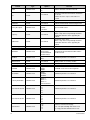
Modes
The mode button is used to access menus which control the major settings and configurations of the unit.
Mode List
Mode
# of
Sub-menus
Purpose
User
Configurable
Main Menu/Login
log into unit and control access
7
Yes
IP Address
allows entry of IP addresses for various components
10
Yes
Port State 1-10
configures the operation of each of the 10 input ports
8 (per port)
Yes
Output
cycles output of aggregate signal into SMPTE or ASI
2
Yes
Tables
cycles through table formats
3
Yes
IPTV
input of Global Settings and Mapped Programs
2
Yes
Audio Format
DVB audio settings
1
Yes
MPE 1-30
configure settings for Multiprotocol Encapsulation
12
Yes
DECAP 1-5
specifies decapsulization
4
Yes
CA1 1-5
conditional access configuration
16
Yes
ENC RED
SWITCH
Encoder Redundancy Switch; used to select PESA LNS8 for
redundancy (only supported option)
1
Yes
MUX Redundancy
Mode
Defines whether the unit is designated a Primary or Back-up
Muxer in a dual-redundancy Mux configuration.
2
Yes
Logs
none-not supported
n/a
n/a
H/W Version
informational only; gives the version number of the installed
hardware
No
S/W Version
informational only; gives the version number of the
installed on-board GUI
No
O/S Version
informational only; gives the version number of the
installed operating system
No
Status Mode
The front panel can be used to completely configure, operate, and maintain the DTA3050.
When first powered up, the unit will activate in Status Mode.
• Status Mode shows the following operating parameters:
♦ operating bit rate.
♦ quantity of data ('D' value).
♦ quantity of IP data ('V' value).
◊ If there is no IP data, an 'F' value will appear, signifying the quantity of fill data.
• By pressing the "Mode" button, each mode menu can be accessed in turn.
• If there is no user activity from the front panel or GUI, the unit automatically shifts to status mode.
♦ The default setting for the for this feature is five minutes; however, it can be user-configured for periods
between one and nine minutes.
Getting Started
16
Administrator Mode
Important: As of Release v.5, all Adtec DTA3050 units are shipped with auto log-out time set to "None". The unit can be
configured by any user without going through a log-in procedure.
To set up an auto-time out:
Step
Action
1
Press the <Up> arrow twice, until the panel reads "Auto Logout Time".
2
Press <Select> until the cursor appears on the word "NONE".
3
Use the <left> and <right arrows> to select a time from 1-9 (minutes).
4
Press <Enter>.
5
<Escape> takes you back to the "Status" menu.
Logging In: If you must log back in after being timed out, you must log into the unit from the front panel as an administrative
user. The default front panel login password is "USER".
To log in, press the following key sequence:
Step
Action
1
Press UP arrow
2
Press SELECT
3
Press ENTER
4
Press RIGHT arrow
5
Press ENTER
Once logged into the unit as an administrative user, the entire suite of configuration possibilities is unlocked for use. Note that
changes made in Administrator Mode are not permanent until a "save all" command is executed or until the menu times out
and returns to Status mode.
17
Getting Started
Intentionally Left Blank
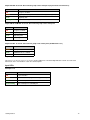
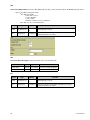
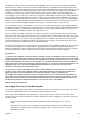
Front Panel Menu Flows
This graphic illustrates the menu flow of the Front Panel in Status and Admin modes:
Pre-programmed Key Sequences
The Adtec DTA3050 has a number of "pre-programmed" shortcut key sequences that can be used to access information about
the router or change the contrast on the LCD display, without having to navigate the menu system:
Key Sequence
Result
MODE + ESCAPE + DOWN arrow
LCD Contrast Down
MODE + ESCAPE + UP arrow
LCD Contrast Up
SELECT + UP arrow
Firmware version
SELECT + DOWN arrow
FPGA Version
SELECT + LEFT arrow
Hardware Version
SELECT + RIGHT arrow
O/S Version
Getting Started
18
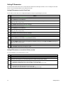
Front-Panel-Only Control Options
The following Settings and Features are only available from the front panel of the DTA3050- there is no GUI support for these
features:
1.“Audio Format”.
• Set to DVB for audio type 6
• Set to ATSC for audio type 0x81
2.Transport stream ID “PAT Tran Strm ID”
3.Resetting the unit.
• Press and hold the "Mode", "Escape", and "Right Arrow" buttons simultaneously, then release them all to affect a
reset.
4.MPE routes.
5.Logging
6.“SAP IP address”
7.Backup and Restore configurations.
8.Enable / Disable auto logout.
19
Getting Started
Communications
LAN
The DTA-3050 incorporates two network ports for Ethernet communications over a Local Area Network (LAN) using the
Internet Protocol (IP). Command and control over a LAN can be accomplished using a Web browser using HTTP.
RS-232
The DTA-3050 provides an RS-232 interface for an experienced user for advanced troubleshooting. An RJ-45 connector
provides a console connection to the DTA-3050, so the unit may be connected directly to a PC’s communications port.
RS-232 Serial Default Parameters
Variable
Setting
Baud Rate
115,200
Data Bits
8
Stop Bit
1
Parity
none
Flow
Control
none; this is required if you are using Hyper Terminal or some other simple terminal application to
communicate with the DTA-3050 via command line.
Ethernet
The DTA-3050 provides an Ethernet (10/100BaseT IEEE 802.3u) interface to communicate with the unit over a Local Area
Network (LAN). Use of the Ethernet port supports connecting multiple units to a single PC through the use of an Ethernet
Concentrator (Hub). The only limitation is the number of ports on the hub and available IP addresses on the network.
Point-to-Point Ethernet connection can be achieved with an Ethernet crossover cable. The DTA-3050 also provides a Gigabit
Ethernet (10/100/1000) interface for IP Destinations. Both ports can provide web administration.
Caution: both interfaces must be on separate subnets. If both interfaces reside on the same IP network, there will be loss of
communication.
Ethernet Default Parameters
Variable
Setting
eth0 10/100
192.168.10.48
eth0 10/100 subnet mask
255.255.255.0
eth1 GigE IP address
192.168.20.48
eth1 GigE subnet mask
255.0.0.0
Gateway IP
0.0.0.0 (defaulted off)
User Name
adtec
Password
none
Getting Started
20
Intentionally Left Blank
User Interface
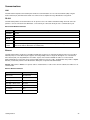
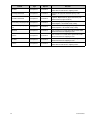
Port and Table Mode
This article compares and contrasts Port Mode and Table Mode on the DTA3050 Router. Table Mode and Port Mode are
accessed using the "Mode" button on the DTA3050's front panel.
Port Mode
Function
Explanation
Pass
All programs and PID’s that are present at the ingress get passed directly to the Egress with no remapping
performed.
In this mode, no PID conflict detection is performed on the Egress, so it is the user’s responsibility to ensure
that no conflicts exist.
Manual
Recommended for most applications.
Only programs and PID’s that are manually added by the user are passed to the Egress.
PID values and program information are mapped using user-defined values.
As a default, the incoming values are used for the outgoing values.
In this mode, the DTA does prevent PID conflicts in the Egress as part of the auto-logic algorithm.
Auto
All programs and PID’s present in the Ingress that are added to the Egress by the user, will be added and
remapped by the DTA Router according an auto-logic algorithm.
In this mode, the DTA does prevent PID conflicts in the Egress as part of the auto-logic algorithm.
SI Injector
NIT only
Used for inputting multiple NIT tables and appending them to NIT Other.
MHP
Injector
Special mode used only for MHP applications.
In this mode, MHP services present in the Ingress can be mapped and associated to services coming in
through other ports.
Table Mode
Table Format
Explanation
DVB
Incoming services are processed using DVB table structure
MPEG
Incoming services are processed using PAT and PMT only
ATSC
Incoming services are processed using ATSC table structure
DCII
Incoming services are processed using Digicypher II table structure
None
Incoming services are processed using information in the manualpidconfigX.xml file (where ‘X’ is
the port number.
These files are located in the /etc/asimux/ directory
23
User Interface
Using the GUI Interface
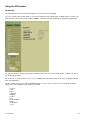
Introduction
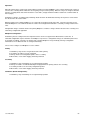
The Adtec DTA3050 features an on-board Graphical User Interface for easy operability.
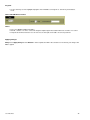
To access the GUI, bring up a web browser, such as Internet Explorer, Netscape Navigator, or Mozilla Firefox, and type your
DTA's IP address into the URL locator, and press "Enter". The DTA's on-board GUI will launch, displaying a page like this:
This page lists basic version and operating time information for the unit, and contains a login window. "USER" (in all caps) is
the default login password.
Also on this screen (and repeated on every screen) is a Status snapshot window, giving current status for ASI Data, ASI Fill,
IPTV, and Redundancy.
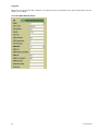
The GUI enables you to interface with the DTA3050 through 11 screens. These screens are accessed with the navigation
buttons in the left-hand window. These buttons are labelled:
• System
• Host
• Inputs
• Mappings
• Outputs
• Tables
• CA
• IP Destinations
• MPE
• Redundancy
• Logs
User Interface
24
Signing in to the GUI
Each screen and its controls are detailed in individual articles which follow. Each screen can be viewed in two ways. If you are
signed into the GUI, each screen has editable controls for the configuration of the router's operations. If you view the screen
without signing in to the GUI, you see a summary screen of the DTA's current settings, without being able to edit them.
Important: note that signing into the GUI and being signed in from the main control panel are two separate actions.
25
User Interface
Intentionally Left Blank
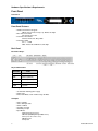
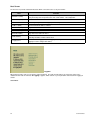
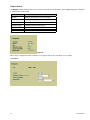
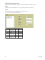
System Screen
The System screen is primarily informational and does not directly impact the operations of the DTA. Six pieces of information
are displayed on this screen:
Data
Function
System Time
Mirrors the CPU time of the PC connected to the DTA Router
System Up Time
total time the unit has been activated since last power-down
S/W Version
Adtec version number of the software installed on this DTA unit
H/W Version
Adtec version number of the hardware installed in this DTA unit
Mux Up Time
total amount of time the unit has been multiplexing during this run; will be a portion of System
Up Time (see above)
Mux Redundancy Time
flag indicator; is feature on or off
Screenshot:
Signed In
When signed in to the GUI, the only difference on the screen is that two fields for updating the GUI password appear.
Screenshot:
User Interface
26
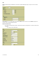
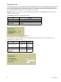
Host Screen
The Host Screen provides information about the DTA's connection to the rest of your network:
Data
Function
MAC Address (Eth0)
a six-byte Media Access Control (MAC) address assigned to the Ethernet ports of the unit;
set by the factory and corresponds to the unit's serial number. Not configurable.
MAC Address (Eth1)
see above
Unit Name
unit name given by the user for login purposes; factory default is "User".
IP Address (Eth0)
the Internet Protocol address of Port 0
Subnet Mask (Eth0)
range of the local subnet for Port 0
IP Address (Eth1)
the Internet Protocol address of Port 1
Subnet Mask (Eth1)
range of the local subnet for Port 1
Default Gateway
an IP address that allows the DTA3050 to communicate with devices not on the local subnet;
defined by IP address and the subnet mask
IP Logging Host
address of the IP Logging Host; if IP Logging is set to "yes" then events are sent to the IP
logging host at the configured IP address
Screenshot:
Logged In
When logged in to the unit, you can edit the settings displayed. The fields described above do not change, but become
editable text-box fields. A new field, "IP Logging", appears, which contains a yes/no pull-down control to turn IP Logging on
and off.
Screenshot:
27
User Interface
User Interface
28
Intentionally Left Blank
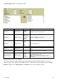
Inputs Screen
The Inputs screen the settings and function of the 10 ASI inputs featured on the DTA3050. For each input, the following is
listed:
Data
Function
State
status of the input; active port, inactive port, or inactive due to stream issue
Format
bytes of incoming data per DVB packet; will display 188 or 204
Mode
type of signal the DTA is passing
Redundancy
this is an on/off indicator signifying whether the feature is enabled/disabled for this input
Data Rate
quantity of data coming in, measured in Mbps
Fill Rate
quantity of fill packets in Mbps
Total Rate
sum of data rate and fill rate
Logged In
When logged into the unit, the Inputs screen offers two levels of access to the unit's programming. The first level looks much
like the screenshot above, with the addition of a clickable "Edit" control:
Screenshot- Inputs Level 1: Portion of Main Window shown
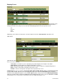
When <Edit> is clicked for a given input, this screen is displayed:
29
User Interface
Screenshot- Inputs Level 2: Portion of Window shown
Control
Type
Options
Function
pull-down menu
Enabled
Disabled
Clear
designates status (role) for this port
pull-down menu
Auto
MHP Injector
SI Injector
Manual
Pass
manual is strongly recommended
Input Tables
pull-down menu
None
MPEG
DCII
DVB
ATSC
specifies table format
Pass CA
pull-down menu
Yes
No
designates if CA programming will be passed on by the
DTA
Redundancy Group
pull-down menu
Inputs 1-10
Disabled
designates an input stream as a backup
pull-down menu
Primary
Backup
Disabled
designates the unit as the primary or the backup in a
two-Mux Master/Slave setup
Note: select 'Disabled' if operating the unit as a
stand-alone.
Input State
Input Mode
Redundancy Role
Available Programs and Current Programs
These windows display the available programming coming into the DTA, and programming streaming out. To make an
available program current, highlight it and click <add>. To delete a program in either window, highlight it and click <remove>.
Important: remember to click <Apply Changes> and <Reload> for any edits to be applied to the DTA.
User Interface
30
Mappings Screen
Main Window shown
(signed in) Signed In When signed into the unit, the Mappings screen offers 8 pages of information on mapped services
coming into the DTA. These pages are accessed via the Group Display buttons across the top of the screen:
• All
• General
• PIDs
• CA 1-5
Additionally, you can filter the view by Input, selected the Input desired via the "Filter Input Port" drop-down menu.
"All" Screen
(Main Window shown)
This screen lists the following:
• Service ID in - ID number for services provided by the provider/originator of the multiplex. Not editable.
• Service ID out -text field; option for assigning new ID numbers to services.
• LCN - Logical Channel Number; used to match Service IDs to channel assignments for programming purposes.
• Name - text box used to provide a descriptive name for the service.
• Provider - text box used to provide a descriptive name for provider of the service.
Control Group The next set of fields lists Stream Type, Mode, PID In, PID Out, Dynamic Track, and Language Descriptor
per Input. Mode, PID Out, Dynamic Track, and Language Descriptor can be edited. The Description field is an optional
mnemonic for descripting the program or service. Service Type designates the type of transmission. MHP Program Number
allows for a program number assignment for Multimedia Home Platform interactive services. The other "General" and "PIDs"
Group Display screen selections filter the information listed on the "All" Group Display screen.
31
User Interface
Conditional Access Screens
Main Window
Shown The Conditional Access (CA) screens list the following:
• Scramble: type of CA being applied; available CA paradigms are listed in the drop-down menu.
• Criteria Length: allows you to specify the length of the access criteria (passcode) in bytes
• Criteria: the actual access criteria (passcode);must be entered in hexadecimal form.
• Private Data Length: CAT private data length, entered in bytes.
♦ Generally this will be provided by the CA provider and is carried in the CA Table.
• Private Data: CAT private data, entered in hexadecimal.
• ECM PID: Entitlement Control Message PID assignment for the program; tells set-top boxes what encryption is being
used.
User Interface
32
Outputs Screen
The Outputs screen summarizes the services being streamed out over the DTA3050's ASI and GigE output ports. Information
is summarized in a table format.
Data
Function
Data Rate
quantity of data going out, measured in Mbps
Fill Rate
quantity of outgoing fill packets, measured in Mbps
Port
physical port identification
Modulation Target
modulation frequency of the output
Egress Clock Mode
type of stream being multicast
Manual Rate
output in bits per second
Screenshot:
Signed In
When you have signed into the GUI, a different screen appears and you can now edit the screen settings:
Screenshot:
33
User Interface
Description:
Control
Type
Options
Function
ASI
Radio button
selected/not
turns ASI on or off
SMPTE-310M
Radio button
selected/not
turns SMPTE-310M on or off
See cautionary note below.
Format
pull-down
menu
188 (bytes)
204 (bytes)
MPEG mode
pull-down
menu
Manual
(recommended)
8 QAM modulations
QPSK
8PSK
modulation of output
Refer to the Modulation Targets Reference for more
information.
Egress Clock
Mode
pull-down
menu
Burst
Byte
Off
type of stream to be multicast
byte - evenly spaced bytes; restricts unit to a clock range of
0.3 Mbps to 50.0 Mbps
burst - each byte transmits back-to-back; range is 2.4 Mbps
to 213.0 Mbps.
Manual Rate
text box
user-defined
bit per second rate of output defined by user
Refer to the Modulation Targets Reference for more
information.
Modulation Target
Caution: after changing from SMPTE to ASI, or from ASI to SPMPTE, the device must be rebooted.
User Interface
34
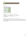
Tables Screen
The Tables screen lists parameters for the three table formats that can run on the DTA3050, and states which table format is
active.
The three table formats are:
• MPEG 2 – PSI (Default is enabled for each port)
• DVB – SI (Default is enabled for each port)
• ATSC – PSIP (Output Only)
A "None" option in the drop-down menu turns tables off.
Signed In
When you have signed into the GUI, the main screen difference is that now all fields are text/pull-down boxes for editing the
screen settings. Additionally, the first control is a pull-down to designate the active table type- DVB, NTSC, or MPEG.
Use of Tables
Service tables provide information about incoming content. Tables allow content in Single Program Transport Streams (SPTS)
and Multi Program Transport Streams (MPTS) to be aggregated into a single MPTS and announced to downstream devices in
a dynamic fashion.
MPEG
Main Window Shown:
MPEG tables organize the transmission of compressed audio and video in a single transport stream.
Control
Type
PAT Rate
text box
assign rate, in tenths of a second, of how often this table is transmitted in the stream
PMT Rate
text box
assign rate, in tenths of a second, of how often this table is transmitted in the stream
CAT Rate
text box
assign rate, in tenths of a second, of how often this table is transmitted in the stream
35
Function
User Interface
DVB
Digital Video Broadcasting - the DTA3050 uses four tables to organize DVB data for ingress and egress. Each is described
below.
Table Sharing: there are two drop-down controls available. Enable switches the feature on and off. Master designates the
unit as the master (control) unit for table insertion.
Network Information Table
• NIT; contains information about a network’s satellite orbit, transponder, tuning parameters, and other network-specific
information.
♦ It is always located on PID 0x0010.
User Interface
36
Control
Enable
Type
pull-down menu
Options
Yes
No
user-defined
Function
switches inclusion of an NIT on and off
determines how often an NIT will be included in
the stream
number entered is expressed in tenths of a
second
Rate
text box
Network Name
text box
user-defined
network's name that will be announced by the NIT
Network ID
text box
user-defined
network's ID that will be announced by the NIT
Delivery Descriptor
pull-down menu
Cable
Satellite
Terrestrial
type of network carrier
user-defined
frequency of the carrier
allows set-top boxes to dynamically determine
information about the carrier supporting the
network
symbol rate of the carrier
allows set-top boxes to dynamically determine
information about the carrier supporting the
network
Frequency
text box
Symbol Rate
text box
user-defined
Modulation Type
text box
user-defined
Polarization
pull-down menu
linear horizontal
linear vertical
circular horizontal
circular vertical
orientation of the transmitter that will send the
encoded stream
East/West
pull-down menu
East
West
modulation parameter; user-defined
Orbital Position
text box
user-defined
orbital position of a receiving satellite
Center Frequency
text box
user-defined
modulation parameter; user-defined
Bandwidth
pull-down menu
6Mghz
7Mghz
8Mghz
bandwidth used; measured in megahertz
Constellation
pull-down menu
QPSK
16-QAM
64-QAM
modulation parameter; user-defined
pull-down menu
Alpha = 1
Alpha = 2
Alpha = 4
Non-hierarchical
modulation parameter; user-defined
pull-down menu
1/2
2/3
3/4
5/6
7/8
modulation parameter; user-defined
pull-down menu
1/2
2/3
3/4
5/6
7/8
modulation parameter; user-defined
pull-down menu
1/32
1/16
1/8
1/4
enhances transmission integrity;
1/32 = low protection/high data transfer rate
1/4 = high protection/low data transfer rate
Hierarchy Information
Code Rate HP Stream
Code Rate LP Stream
Guard Interval
37
User Interface
Transmission Mode
pull-down menu
2K
8K
controls speed at which the DTA re-transmits the
re-muxed stream
Other Frequency Flag
pull-down menu
Yes
No
modulation parameter; user-defined
User Interface
38
SDT
Service Description Table;;The Service Description table describes services which are part on an MPEG2 transport stream.
• There is one SDT per transport stream.
♦ The SDT may include:
◊ name of the service.
◊ service identifier.
◊ service status.
◊ whether or not the service is scrambled.
♦ The SDT uses the reserved PID 0x0011.
Control
Type
Options
Function
Enable
pull-down menu
Yes
No
Switch table type on or off
Rate
text input box
user-defined
determines how often an SDT will be included in the stream;
measured in tenths of a second
TOT
Local Time Offset Descriptor; allows for local time to be converted from UTC.
Control
Type
Options
Function
Country Code
text field
user-defined
three-letter country designator
Country Time Zone
text field
user-defined
numeric time zone indicator
EIT
Control
Type
Options
Function
Enable
pull-down menu
Yes
No
Switch table type on or off
Rate
text input box
user-defined
determines how often an EIT will be included in the stream;
measured in tenths of a second
39
User Interface
ATSC
The Advanced Television Systems Committee (ATSC) developed standards which became HDTV. Like DVB tables, ATSC
uses additional tables to function as extensions of the basic MPEG-2 system layer. Called Program and System Information
Protocol (PSIP) tables, they allow service providers to offer a multitude of broadcast products to viewers. ATSC was created
for terrestrial and cable broadcast systems.
PSIP Tables include:
• Virtual Channel Table (VCT): list and defines all the channels in a transport stream, including source IDs used by
the EIT (which see) to generate the Electronic Program Guide.
• Master Guide Table (MGT): indexes other tables in the PSIP standard; defines table sizes, version numbers, and
PID values.
• System Time Table (STT): single packet that contains the current time; enables the receiver to begin events per
schedule.
• Rating Region Table (RRT): provides content-based program rating system information for countries that have
standardized ratings.
• Event Information Table (EIT): defines the events (programs) contained in the transport stream for a 3-hour block of
time; uses data from the VCT to populate the Electronic Program Guide; per ASTC, between 4 and 128 EITs must be
in the transport stream at any given time; can contain up to 16 days' worth of programming information.
User Interface
40
Control
Type
Options
Function
VCT-Rate
text input box
user-defined
rate, in tenths of a second, that a Virtual Channel
Table will be included in the outgoing stream.
VCT- Major Channel #
text input box
user-defined
announce the physical channel/frequency of the
carrier
VCT- Minor Channel #
text input box
user-defined
segments Major Channels (physical channels) into
Minor Channels (logical channels)
VCT- Primary Language Code text input box
user-defined
specifies language being supported
ENG, ENglish, is the default factory setting
VCT- Secondary Language
Code
text input box
user-defined
specifies a secondary language being supported
SPAN, Spanish, is the default factory setting
MGT Rate
text input box
user-defined
rate, in tenths of a second, that a Master Guide Table
will be included in the outgoing stream.
SIT Rate
text input box
user-defined
rate, in tenths of a second, that a System Time Table
will be included in the outgoing stream.
RRT Rate
text input box
user-defined
rate, in tenths of a second, that a Rating Region Table
will be included in the outgoing stream.
EIT Rate
text input box
user-defined
rate, in tenths of a second, that an Event Information
Table will be included in the outgoing stream.
41
User Interface
Intentionally Left Blank
Conditional Access Screen
The Conditional Access screen shows the status of scrambled services and related decryption operations to make those
services accessible to authorized viewers.
The informational screen contains the following information for each CA-enabled service (up to 5):
Data
Function
Enable #
describes which Conditional Access System (CAS) provider's encryption scheme is in use
Super CAS ID
provided by CAS manufacturer
CAS System ID
provided by CAS manufacturer
ECMG IP
use the IP address the of the CAS hardware
ECMG Port
set to the port of the CAS hardware
ECMG Channel ID
provided by CAS manufacturer
ECMG Crypto Period
provided by CAS manufacturer
ECMG Keep Alive
provided by CAS manufacturer
EMMG Mode
TCP and are support; this value will be provided by the CAS manufacturer
EMMG Port
set to the port configured on the CAS hardware
EMMG Maximum
provided by CAS manufacturer
EMMG PID
enter value in hexadecimal format, or leave blank and the DTA will autoselect a free PID
EMMG Data Channel ID
provided by CAS manufacturer
EMMG Keep Alive
provided by CAS manufacturer
Private Data Link
provided by CAS manufacturer
Private Data
provided by CAS manufacturer
User Interface
42
Logged In:
When you have signed into the GUI, a different screen appears (one for each enabled service; up to 5 total) and you can now
edit the screen settings:
Screenshot (Main Window shown):
43
User Interface
Parameter Descriptions:
Parameter
Type
Options
pull-down menu
No
Yes
Enable #
pull-down menu
No
Irdeto
Eurocast
Conax
Keyfly
AdtecOST (AES)
XCrypt
Super CAS ID
text field
user-defined
CAS System ID
text field
user-defined
ECMG IP
text field
user-defined
ECMG Port
text field
user-defined
ECMG Channel ID
text field
user-defined
ECMG Crypto Period
text field
user-defined
ECMG Keep Alive
text field
user-defined
EMMG Mode
pull-down menu
UDP
TCP
EMMG Port
text field
user-defined
EMMG Maximum
text field
user-defined
EMMG PID
text field
user-defined
EMMG Data Channel ID
text field
user-defined
EMMG Keep Alive
text field
user-defined
Private Data Link
text field
user-defined
Private Data
text field
user-defined
Adtec AES Decrypt
User Interface
44
Intentionally Left Blank
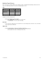
IP Destinations Screen
In View-Only mode (not signed into the GUI), the IP Destinations screen gives the following information:
Data
Function
IPA
destination's IP Address
Port
egress port assignment
Src Port
shows the Source Port that will be stamped in the header packet
IP TTL
time to live; number of iterations the multicast can go through before it expires
Name
destination name
Destination
destination's IP domain
Type
stream format
Action
Click the <View> link to access the next level.
Once <View> has been clicked, the screen shifts to this configuration:
45
User Interface
Each of the four tables contains specific information. General Table
Data
Function
Name
IP destination address
Modulation Target
modulation type; recommended to be set to manual
IPA
destination's IP domain
Bit Rate
rate of transport in bits per second
Port
port assignment on the DTA this stream is using
IP TTL
time-to-live
Src Port
sets the Source Port stamp in the header packet
State
on or off (enablement)
Programs Table
Lists assigned programs.
Tables Table
Data
Function
Type
table format selected
PAT
Program Association Table; lists all the programs contained in the transport stream; shows the PID value for the PMT
associated with each program.
The PAT is always found on PID 0x0000.
DVB-NIT Table
Data
Function
Enable
on or off
Network Name
user-entered; Network's name as appears in program guides
NIT Rate
frequency with which an NIT is sent in the stream
Network ID
ID code of the network
Symbol Rate
gross bit rate of the stream
Original Network ID
network ID code as used by the signal's provider
RF Frequency
RF frequency of the carrier being streamed through the DTA
User Interface
46
Signed In
When signed in to the unit, you now have the options, under "Actions" of editing or deleting an existing IP destination, or
adding a new one (screen button in upper right; see first illustration).
When "Add New" is selected, the following screen appears:
General
Control
Type
Options
Name
text box
User-defined
IPA
text box
User-defined
Port
text box
User-defined
Src Port
text box
User-defined
Modulation Range
text box
User-defined
Bit Rate
text box
User-defined
IP TTL
text box
Enable
pull-down
Checked
Not checked
Transmit
pull-down
UDP
RTP
Interface
pull-down
eth0
eth1
47
User Interface
Programs
• Use the arrow keys to move highlighted programs from "Available" to "Assigned" as desired for your broadcast
needs.
Tables and DVB-NIT Screenshot:
Tables
• Type: select MPEG or DVB format tables.
• For PAT, numbers 1-5 can be selected to designate output Program Association Table rates in tenths of a second.
• Transport Stream ID: text field, for ease of reference; the transport stream tables are to be injected into.
Applying Changes
Always click <Apply Changes> and <Reload> in order to update the DTA. If these buttons are not clicked, your changes will
not be applied.
User Interface
48
Intentionally Left Blank
Multi-Protocol Encapsulation Screen
Multi-Protocol Encapsulation (MPE) is combining unicast and multicast Ethernet IP data into one output.
Display:
The Multi-Protocol Encapsulation (MPE) screen is a flag indicating whether MPE is enabled or not.
Signed In
When signed in to the unit, you can switch MPE on or off for up to 32 routes.
The screen now looks like this (Main Window shown):
Control
Type
Purpose
Options
Route
pull-down menu
1-32
Name
text box
user-defined
IP Address
text box
user-defined
PID
text box
user-defined
Max Rate
text box
user-defined
Enabled
pull-down menu
Yes
No
49
User Interface
Unicast Support
The support of Unicast is straightforward since Ethernet frames are directed to the DTA-3050’s Ethernet port as a “default
gateway.” As a default gateway, the DTA-3050 will either route the IP datagram, if there is an explicit route for the IP address,
or silently discard the IP datagram if there is no route for the destination.
A unicast packet is one that has a non-broadcast MAC address associated with it, for example, the most significant byte of the
MAC address has the least significant bit set to ‘0’. Unicast IP addresses that may be supported will fall into the standard
class range of A, B, or C. The DTA-3050 has a provision to route unicast IP datagrams based on an IP and subnet mask
structure. Example:
Parameter
Value
IP address
10.10.10.0
Mask
255.255.255.0 “C Class”
Resulting IP addresses to be routed
10.10.10.0 to 10.10.10.255
Assigned MAC Address
0x00 00 00 00 00 00 to 0x00 FF FF FF FF FF, and excluding 0xFF FF FF FF
FF FF
For Unicast support, there is no correlation between the IP address and the MAC address as will be described in the Multicast
section.
Multicast Support
MPE support of Multicast is not as straightforward to support, since Linux causes unique challenges. Unlike Unicast, where all
devices communicates to the Multiplexer over the single hardware MAC address assigned to the Multiplexer; the support of
Multicast requires that each Multicast address that is going to be enabled must be statically entered into a list and the Ethernet
port enables a “hash” table, allowing specific Multicast MAC addresses to be enabled. What makes this somewhat daunting is
the fact that there are a finite number of multicast addresses that may be supported.
Multicast is considered as “class D” addressing and falls within the IP address range of 224.0.0.0 to 239.255.255.255. The
corresponding MAC address range is 0x01 00 5E 00 00 00 to 0x01 00 5E 7F FF FF and is derived as follows:
• 1st three octets and the most significant bit of the 4th byte’s octet are always set to 0x01 00 5E ‘1’.
• The least significant bits of the 4th byte, and bytes five and six are the last three bytes of the multicast IP address.
Example:
Parameter
Value
Multicast IP Address
239.1.1.10
MAC Preamble
0x01 00 5E
Multicast to MAC Mapping:
User Interface
50
Redundancy Screen
The Adtec DTA3050 can be used in conjunction with a second DTA3050 as a back-up. The unit designated as the back-up will
receive setting information from the Primary unit (the Primary unit essentially clones itself onto the back-up) and monitors the
Primary's input and output activity. Should the Primary unit suffer an output failure, the back-up immediately begins to stream
the same programming, providing greater service reliability for your customers.
Important: In order to use this feature, your DTA3050 must be running firmware version 6.03.02. Contact Adtec Technical
Support to obtain this firmware.
The Redundancy Screen lists the following information:
Data
Function
Mux Redundancy Role
which role this unit is designated to perform
Mux Redundancy Other IP
the IP address of the other unit in a redundant pair
Encoder Switch
switch type
Screenshot:
Signed In
If the Redundancy screen is viewed while signed in, the table doesn't change in appearance, except for the presence of
pull-down menus for editing the settings:
Data
Control Type
Options
Mux Redundancy Role
pull-down menu
Disabled
Primary
Back-up
Mux Redundancy Other IP
text field
user-defined
Encoder Switch
pull-down menu
PESA LNS8
none
Screenshot:
51
User Interface
Encoder Redundancy
The DTA3050 enables encoder redundancy for Adtec's line of encoders. Three types of redundancy are supported:
• 1:1
•N+1
•N+2
1:1 Encoder Redundancy
The most basic form of redundancy is 1:1. Input-port pairs on the DTA-3050 support redundancy. The configuration is set as
a Boolean for 1:1 redundancy on any of the ten input ports. The port pairs are: 1 and 2, 3 and 4, 5 and 6, 7 and 8, and 9 and
10. If either port in a pairing group is set to be redundant, then both ports are put in redundant mode. Once a port has been
defined as redundant, the paired port will become the identical configuration of the port set to redundant.
Redundancy is determined monitoring the status of sync and reception of table information. In the event the primary port is no
longer receiving table information from the encoder, the port is disabled and the secondary is placed on line.
1:1 Encoder Redundancy Illustration:
1:1 Encoder Redundancy Connections-Graphic
User Interface
52
53
User Interface
N + 1 Encoder Redundancy and N + 2 Encoder Redundancy
N+1 and N+2 encoder redundancy allow one encoder to act as a redundant encoder for a group of encoders. Though 1:1
provides one backup for each primary encoder, this level of redundancy is seldom required, since the Edje-2x00 encoders are
highly reliable and seldom fail. Therefore, N+1 and N+2 encoder redundancy provide a more economical solution.
To support N+1 or N+2 redundancy requires an external router/switcher be connected before the encoders. The Pesa LNS8
has been integrated into the DTA-3050 design.
N +1 Encoder Redundancy- Illustration
4 + 1 Redundancy Example
User Interface
54
N + 2 Encoder Redundancy- Illustration
55
User Interface
4 + 2 Redundancy- Example
Redundancy Pinout
The redundancy cable between the DTA-3050 and the Pesa LNS8 is an RS-232 cross-over cable and is pinned as follows:
DB-9 Female
DB-9 Female
Pin 2
Pin 3
Pin 3
Pin 2
Pin 5
Pin 5
User Interface
56
Multiplexer Redundancy
The DTA-3050 is designed to provide 1:1 encoder redundancy when connected to a second DTA-3050 encoder. No external
redundancy switch is required to provide 1:1 redundancy – all redundancy support is contained in the unit. The secondary
Multiplexer will be “upstream” to the primary Multiplexer. When the secondary is online, the output will flow through the
primary. When the secondary is offline, then the output will simply terminate into the primary and the primary’s output will be
the egress present at the output.
Redundancy is controlled by the primary Multiplexer. A relay has been added to the product and when the normally closed
(NC) circuit, in its non-energized state, will route the secondary traffic to the output. When the relay is energized, output will be
from the primary mux.
To determine the status of an encoder (Primary / Secondary), the user can look in the upper-right corner of the LCD display.
The LCD screen shows a letter to denote the redundancy status:
• P = Primary
• S = Secondary.
A blank in the upper-right hand corner denotes stand-alone mode.
Connections
Redundancy is achieved by cabling two DTA-3050’s in a serial fashion as shown in the following figure:
57
User Interface
Intentionally Left Blank
Operations
When the primary mux is powered up and operational, all output is from the primary. In the event the primary fails or power is
removed, the secondary will be switched in de-energizing a relay inside the primary. When the relay is de-energized, all traffic
from the secondary will be routed from the ASI In 1 to the ASI 1 (output) and ASI In 2 will be routed in the a similar fashion to
ASI 2 (output).
Redundancy control is accomplished by monitoring critical function in the DTA-3050 and if any fail or power is removed from
the unit, then the unit is taken offline.
Both the primary and secondary Multiplexers are connected via an Ethernet LAN connection. The LAN connection ensures
that both Multiplexers can communicate with one another and configuration information is constantly exchanged between the
units.
Configuration changes should be made to the primary Multiplexer, and these changes will be reflected on the secondary via a
redundancy-configuration application.
Multiplexer Configuration
Redundancy must be configured via the front panel interface and is not support via the Web interface at this time. A
redundant configuration requires that when one Multiplexer experiences a configuration change, the redundant partner must
be changed accordingly. Therefore, the primary and secondary Multiplexer must periodically exchange configuration
information to ensure that both units are configured identically.
The user must configure each Multiplexer’s role as follows:
Primary
1. Redundancy relay must be energized to become online primary.
2. Secondary’s IP address must be configured.
3. Primary should send configuration updates to the secondary.
4. When online, events and IP logging should be performed.
Secondary
1. Redundancy relay should always be energized during operation
2. Primary’s IP address should automatically be displayed when the primary contacts the secondary
3. Secondary should receive and verify configuration updates
4. When online, events and IP logging should be performed
Standalone (Default Configuration)
1. Redundancy relay should always be energized during operation.
User Interface
58
Logs Screen
Two Log reports are available from this screen, Multiplexer Logs and OS Logs.
Multiplexer Logs: to access Multiplexer logs, select the type desired (choices are All Mux, Major Mux, and Minor Mux) from
the pull-down menu, and press the <Submit Query> button.
OS Logs: "All" is the only option on the OS Logs pull-down; press the <Submit Query> button to complete the request.
Display
Reports will display the following information, although in a linear table format:
Heading
Information Contained
ID
identification number of an event
Date
date an event occured
Time
time of the event (in 24-hour format)
Application
the application reporting the event
Severity
Major- events that impact service
Minor-events that no dont impact service
Info- Information only
Config- configuration changes
Notice- event notices
Message
text that describes the event
There is no "logged in" option on the Logs screen.
59
User Interface
Updates Screen
The Upgrade Tab is used to easily select and upgrade your unit's firmware from the available versions, and to unlock optional
features available. There are two sub-tabs on this screen- Firmware and Features.
Firmware
Screenshot:
Image reduced for clarity Installed Versions are firmware versions that have been installed on your device and can be
selected as the current operating version. To select one of these versions, simply click on the <Select> button associated with
the version. Due to the caching properties of your browser, it is necessary to clear your cache or restart the browser to make
sure that the new application pages load. Click the <Upgrade> tab a second time to view the currently loaded versions. Other
Controls
• Delete: clicking the <Delete> button will delete that stored firmware version from your device.
• Restore: the <Restore> button only appears next to the currently installed firmware version. Clicking <Restore> will
reset all user-defined configuration settings back to the factory defaults.
♦ This includes the IP Address defined for the unit and the removal of any Feature Keys.
♦ If <Restore> is selected, the unit will ask for a confirmation before carrying out the reset.
♦ If your broswer doesn't re-direct after <Restore> is selected, close it and re-open it, directed to the IP
Address 192.168.10.48 (the factory default IPA).
To upload new firmware versions, click on the <Upload> button, then click on the <Upload> button on the "Adtec Uploader"
pop-up that appears, and select the desired firmware version by clicking it. After the new version is uploaded, a pop-up screen
will confirm its availability on the device.
User Interface
60
Features
Main Window Shown; screenshot shows optional Feature Keys enabled. Your DTA may differ.
Clicking the "Input Key" button will pop-up a screen so that the key sequence can be entered. On the DTA, ASI Input ports
1-5 will ship unlocked. Optional features include Conditional Access and ASI Input ports 6-10. Contact your Adtec sales
representative regarding the purchase of feature keys. Check www.adtecinc.com for news regarding new features that may be
available for the DTA-3050.
61
User Interface
Modulation Targets Reference
When connecting to a modulator (QAM for cable or QPSK for satellite), the DTA3050 will automatically calculate the desired
egress rate and NIT table parameters, based on the modulation target selected.
QAM
Modulation Target
188 Byte Mode
204 Byte Mode
QAM64NTSC
5.056900 Msps
4.660400 Msps
QAM256NTSC
5.360530 Msps
4.940000 Msps
QAM64PAL
6.742500 Msps
6.213400 Msps
QAM256PAL
7.147400 Msps
6.586700 Msps
QPSK
For QPSK, refer to the following formula:
• Bit Rate= Symbol Rate*(2* Viterbi * 188/204)
♦ where Symbol Rate = Symbol Rate of the satellite carrier
♦ and Viterbi Rate = 1/2, 2/3, 3/4, 5/6, or 7/8 coding
Manual Rate
• In the event the pre-configured rates are not desired, the user can manually enter the desired rate. This is the default
mode of operation on the DTA3050.
SMPTE-310M
• Provides 19,392,568.46 bps of output over the SMPTE-310M interface.
♦ The ASI port operates concurrently, but at a fixed rate of 19,392,568.46 bps.
♦ The ASI port can be used as a "monitor port" in this mode.
User Interface
62
Manual Upgrades
Important Notes
• This upgrade must be executed from the local area network that the unit- or units- are attached to.
♦ There is a limitation in the Units FTP server and it does not work through NAT devices.
♦ Please turn off any personal firewall software before running the upgrade.
◊ If you do not want to turn off personal firewalls, then ports 43 and 79 must be opened up.
Upgrading the Unit
Follow these steps:
Step
Action
1
Save the file to your PC.
2
Run the file.
3
When the command prompt window opens type ' upgrade ', press the space bar, type your unit's IP address, and
press < Enter>.
Example: C:\DTA_Upgrade\upgrade 192.168.10.48 <Enter>
4
Follow on the screen prompts.
Restoring the Backup
The upgrade creates a tar file at the root of the file system. The file is named <date>_system_backup.tgz. This file can be
un-tared and the unit will revert to the previous state.
In the event you want to revert back to the old version and configuration, here are the steps to restore the unit to the previous
state:
Step
Action
1
rcasimux stop
2
cd /
3
pwd.
This MUST respond with / this command lets you know what directory you are in.
You must be in the root of the filesystem, which is '/ not root'.
4
tar –xvzf <date>_system_backup.tgz
5
shutdown –rn now
The steps outlined above will un-tar the back-up, including the configuration. Additional Support Contact Support
(615-256-6619 or 904-720-2003 x 241) if you have any problems with the upgrade.
63
User Interface
Operations
Manual PID Injection - Overview
The DTA's ingress logic requires Service Information (SI) to present a list of programs or PIDs to map to the output. Manual
PID injection is used to pass a program or PID that is not referenced in the SI. The most common example of manual PID
injection is a transport stream from an SI generator or Transport Stream spooler. Manual PID injection mode is useful for:
• PID injection - passing a PID or PIDs unreferenced by the SI/PSI/PSIP generated by the DTA.
• Program injection - passing a PID or PIDs and referencing them in the SI/PSI/PSIP generated by the DTA.
• SI/PSI/PSIP injection - passing PIDs that are tables.
• Elementary Stream Addition - adding a PID or PIDs to an existing program (or programs).
This article will explain in detail how to use manual PID injection modes, and provide examples of the process in use.
Requirements
Attention: referenced third-party software is suggested; Adtec does not endorse any third-party software product over
another.
• Telnet/ssh client: http://the.earth/li~sgtatham/putty/latest/x86/putty.exe
• File transfer utility: http://winscp.net/download/winscp425.exe
• Text Editor: http://www.editpadpro.com/download.html ( note: program is not freeware)
• Correct version of the DTA software.
♦ must use version 6.02.04a (or higher) software.
• Know the value(s) of the PIDs you want to inject.
• A manualpidconfigX.xml file with entries that match your application.
Procedure
Step
Action
1
Connect the transport streaming source device to the desired input.
2
Edit the manualpidconfig file with the desired values.
(You can either get the file from the unit or use one of the samples located at adtecftp.com.
3
Transfer the file back to the unit (to /var/local/lib/asimux).
4
From the unit's Front Panel or browser-based GUI, configure the port that the transport streaming source device is
connected to as follows:
Port State = Enabled
Port Mode = Manual
Tables = None
5
Reset the unit.
6
Confirm that PIDs are present from the Mappings page.
They will show up as program 100000, and be listed under "Components".
Examples/Samples
PID Injection
This sample will pass an unreferenced PID, 0x1234 from Input 5:
<?xml version="1.0" encoding="UTF-8"?> <configuration xmlns:xi="!http://www.w3.org/2001/XInclude">
<manual_pid_config index="5">
<pid>
<pid_in base="16">1234</pid_in>
<pid_out
base="16">1234</pid_out>
<stream_type>Private</stream_type>
</pid> </manual_pid_config>
</configuration>
SI/PSI/PSIP Injection
The sample below will pass PIDs ox10 (NIT) and Ox11 (SDT) from Input 5. When using this mode you must turn off NIT and
65
Operations
SDT generation by the DTA. If your SI Generator is to supply all tables, you should disable all tables in the DTA. This can be
accomplished from the Tables menu (Front Panel) or Tables page in the GUI.
<?xml version="1.0" encoding="UTF-8"?> <configuration xmlns:xi=!"http://www.w3.org/2001/XInclude">
<manual_pid_config index="5">
<pid>
<pid_in base="16">10</pid_in>
<pid_out
base="16">10</pid_out>
<stream_type>Private</stream_type>
</pid>
<pid>
<pid_in
base="16">11</pid_in>
<pid_out base="16">11</pid_out>
<stream_type>Private</stream_type>
</pid>
</manual_pid_config> </configuration>
Program Injection
The following sample will pass PID 0x257 from Input 5, and build a program number 9999 (PMT) 0x256 that references it.
<?xml version="1.0" encoding="UTF-8"?> <configuration xmlns:xi="!http://www.w3.org/2001/XInclude">
<manual_pid_config index="5">
<pid>
<program_number_out base="10">9999</program_number_out>
<pid_in base="16">0</pid_in>
<pid_out base="16">256</pid_out>
<stream_type>PMT</stream_type>
</pid>
<pid>
<program_number_out
base="10">9999</program_number_out>
<pid_in base="16">257</pid_in>
<pid_out
base="16">257</pid_out>
<stream_type>Private</stream_type>
</pid>
</manual_pid_config>
</configuration>
Elementary Stream Addition
The sample below will pass PIDs Oxcf and Oxd) from Input 5 ans add htem to porgram number 2 sourced from input 2. This
sample is from an MPH injection application. If you wanted to add the MHP objects to additional programs, you would add
additional xml notes with the corresponding <port> and <program_number_out> elements.
<?xml version="1.0" encoding="UTF-8"?> <configuration xmlns:xi="http://www.w3.org/2001/XInclude">
<manual_pid_config index="10">
<pid>
<port>2</port>
<program_number_out_base="10">2</program_number_out>
<pid_in base="16">cf</pid_in>
<pid_out base="16">cf</pid_out>
<stream_type>Type B</stream_type>
</pid>
</manual_pid_config>
</configuration>
XML Elements
Complete breakdown on all the XML elements:
XML Element
Function
<manual_pid_config_index>
signals the application as to which input to look for the PIDs to pass
<port>
used in conjunction with <program_number_out> and signalls the egress as to which program
(PMT) to update with the injected PIDs.
<pid_in>
signals the ingres as to which PID to look for.
<pid_out>
signals the egress to pass the <pid_in> on the defined value.
<stream_type>
signals the egress (PMT) how to define the injected PIDs.
Operations
66
Valid Stream Types
List of valid stream types:
• "Mpg1Vid"
• "Mpg2Vid "
• "Mpg1Aud"
• "Mpg2Aud "
• "Private"
• "Ac3Aud "
• "MHEG"
• "DSMCC "
• "H222"
• "Type A"
• "Type B"
• "Type C"
• "Type D"
• "Aux"
• "H264Vid"
• "DCIIVid"
• "ATSCAud"
• "SubTitl"
• "PMT"
• "PCR"
• "Teletxt"
• "SubTitl"
• "VbiData"
• "VbiTTxt "
• "EMM"
• "ECM"
67
Operations
Intentionally Left Blank
Using XCrypt with the DTA3050
In addition to functioning as a MUX for Digital Turn Around, the DTA3050 can also function as a scrambler with many
Conditional Access systems. This article describes setting the DTA3050 to scramble using XCrypt.
This article should be considered a DRAFT; actual procedures may vary based on local installation.
Network Communications
Communications between the DTA and XCrypt server are to reside on the management network (eth0). TSOIP is to reside on
the Media network (eth1, aka GIG-E). These networks must be separated physically.
Configure CA for XCrypt
Main Window shown
Operations
68
On the Conditional Access page, select the CA tab you want to set. Up to five different CA system parameter settings can be
stored on the unit, one per tab. These settings are saved on the device as a configuration file, but are not transferrable to
another DTA device. Set the parameters as follows:
Parameter
Setting
Enable
select XCrypt from the drop-down menu
Super CAS ID
enter the CAS ID (value supplied by XCrypt), plus four zeros (0000)
CAS System ID
enter the CAS ID (value supplied by XCrypt)
ECMG IP
enter the IP address of the XCrypt server
ECMG Port
set to match Host Port (the default is the setting provided by XCrypt )
ECMG Channel ID
enter 0001
ECMG Crypto Period
enter 10
ECMG Keep Alive
enter 5
EMMG Mode
select TCP from the pull-down menu
EMMG Port
set to match Host Port (the default is the setting provided by XCrypt )
EMMG Maximum Bandwidth
enter 100 (maximum bandwith of the DTA3050 )
EMMG PID
set to hex value (user-defined)
EMMG Channel ID
enter 0001
EMMG Keep Alive
enter 5
Private Data Length
enter value supplied by XCrypt
Private Data
enter value supplied by XCrypt
You must click <Apply Changes> to apply and save your CA configuration!
69
Operations
Encrypting a Service
After configuring the CA type, access the Mappings page in the UI, then click on the CA tab corresponding to the CA tab you
just configured (in our example, CA1):
Main Window shown
Set the parameters on this page according to the following table:
Parameter
Setting
Scramble
select XCrypt from the pull-down menu, with the numeral that corresponds to the CA tab that XCrypt
was configured on.
Criteria Length
divide the Criteria number (next field) by 2; enter the result. (This is the Criteria value expressed in
bits.)
Criteria
enter the Criteria value supplied by XCrypt
Private Data
Length
divide the Private Data number (next field) by 2; enter the result. (This is the Private Data value
expressed in bits.)
Private Data
enter the Private Data number supplied by Xcrypt
ECM PID
hexadecimal value; user-defined.
Operations
70
Intentionally Left Blank
Appendix
Contacting Customer Support
Adtec Digital's Support Services
Technical Support and Customer Service includes troubleshooting product/system functional operations concerning Adtec
equipment, embedded systems and single device issues; Service Order generation, processing and tracking; Warranty claim
processing; and on-site system evaluation and maintenance. Technical Support plans do not include customer training
programs. Programs incorporating customer training are defined in the Training Services Policy. Customer Services
technicians provide limited instruction during a support call/email/fax in order to facilitate checking for proper equipment
operation.
Telephone and Email Support
• Telephone: 615-256-6619 ext. 166
• Email: [email protected]
• Internet: www.adtecinc.com/supportrequest/
Adtec Digital offers telephone, email and fax support, warranty and service related inquiries during normal business hours:
9:00am to 5:00pm Central Standard Time (CST), Monday through Friday, holidays excepted. Support Requests can also be
submitted on-line.
All inquiries will be processed in the order in which they are received and by the criteria outlined in the Call Response Order.
Inquiries and inquiry responses made after 5:00 PM (CST) weekdays, Saturday, Sunday or on an Adtec-recognized holiday
will be processed the next business day in the order received.
Callers on hold and returned calls will be prioritized by the following criteria:
• Priority-24 Subscription Customers
• Standard-Priority Subscription Customers
• All customers that have purchased Installation & Training, within 90 days of the installation
• Adtec Certified Operators (ACO)
• Limited Level Support, Warranty & Service Requests
• Multi-device system installations that have purchased Installation & Training from Adtec
• Distributors
• System Integrators
• Multi-device systems
• Single device users
Information needed for Support
To help expedite the troubleshooting process, please be prepared to provide the following information to the support
representative:
• Product(s) affected: please provide a list of the Adtec Products involved including the Revision Number for each
affected product.
• Description of the Problem: please include a detailed description of the problem. Include the approximate time and
day the problem occurred, the spot ID of the material being inserted and what the operator reported about the
incident. It is also helpful to note any recent changes to the system. More information is always better than too little
information.
• Your Contact Data: please include contact information so we can reach you to discuss how to fix the problem,
additional troubleshooting steps that are required or to gather more complete information regarding the problem.
Please include your facility name (or call letters), your name, title, email address, telephone number, hours of work,
and other contact persons if you are not available.
71
Appendix
Advanced Support Plans
In addition to our basic Inquiry Response Policy, Adtec offers two advanced levels of priority inquiry support:
Standard-Priority and Priority-24. The Standard-Priority & Priority-24 plans provide guaranteed* response times with the
Priority-24 plan offering after hours and holiday support. Standard-Priority support is included with the Adtec Certified Operator
(ACO) training. Contact Adtec Sales to upgrade your current support plan.
Standard-Priority Support Plan Description
Customers can improve upon our normal call processing times and can expedite inquiry support responses through our
subscription Standard-Priority service plan. Under this plan all telephone inquiries are guaranteed* a telephone response of no
more than 4 hours after they are received (within the designated hours of operation). Telephone inquiries received by 4:00 PM
(CST) on weekdays- excluding Adtec holidays- are guaranteed a same-day telephone response. However, inquiry responses
may be made after hours until 8:00 PM (CST). Email and fax inquiries are limited in scope to normal business hours, excluding
holidays. Standard-Priority customers are entitled to a 10% discount on site visit and training charges after the initial
system/product installation and training. Standard-Priority customers also receive a 3-day turnaround time guarantee* on
warranty and non-warranty repairs on Adtec manufactured equipment, excluding Studio Encoders.
Priority - 24 Support Plan (24 Hour) Description
In addition to our Standard-Support plan, after hours, weekend and holiday support is available with the Priority-24 support
plan. This plan is a subscription only service available for service inquiries 24 hours a day, 7 days a week. All telephone
inquiries are guaranteed* a telephone response time of no more than 2 hours. Email and fax inquiries are limited in scope to
normal business hours, excluding holidays. Calls after 5:00 PM will be forwarded to a Customer Services representative on
call. Priority-24 customers are entitled to a 25% discount on site visit and training charges, after the initial system/product
installation and training. Priority-24 customers also receive a 1- day turnaround time guarantee* on warranty and
non-warranty repairs on Adtec-manufactured equipment, excluding Studio Encoders.
Plan Comparisons
Feature/
Plan Name
Priority-24
Standard Priority
Limited
Hours
24 Hours/Day; 7 Days/Week
9:00 AM – 5:00 PM, (U.S.Central Standard Time),
ExcludesWeekends & Holidays
Call Response Time
Same day- 2 hours (1st in order of call list)
Same Day: 4 Hours (2nd in order of call list)
48 Hours
Discounted Site Visits
25%
10%
None
Discounted Training
25%
10%
None
Repair Service
Guaranteed* 1 Day Turnaround
3 Day Turnaround
None
* A one-month free service extension will be awarded if Adtec fails to meet its service guarantee.
Appendix
72
Troubleshooting Guide: DTA3050
Problem
Solution
I have video, but no audio, on my
receiver
Check the table type on your Mux input.
If table type is set to ATSC, then manually change your DTA's Audio Input setting to
ATSC (the default is DVB) from the front panel (cannot be done on the GUI)
I have an old mux, and my IP out
does not appear on my GIGE
network
Telnet on port 43, root, 1root!
Next, issue this command:
IP route add 224.0.0.0/4 dev eth1
My web interface (GUI) went away
Telnet on port 43, root, 1root!
Next, issue this command:
rcapache restart
I am missing one of my services on
the output. Inputs are on manual
mode
On the Mappings page in the GUI, are there red boxes around one or more of the
listed services? If so, there is a service ID conflict. To resolve:
1. Change service numbers manually, or clear your inputs.
2. Start over with them in Auto Mode and allow the mux to auto-assign, then set
inputs back to Manual.
All detected services will be passed in the output multiplex without conflict. Individual
services and service components can be dropped to clean up the output
New IP addresses don't work
Check: are your eth0 and eth1 addresses on the same subnet?
If so change one of them to a different subnet
Input indicators are constantly red
check to ensure that the appropriate ASI input port has a cable securely attached.
Also, ensure that the cable type is a standard 75-ohm coaxial cable.
Input indicators are neither red or
green
the port has been administratively disabled. Re-enable the port via the front panel or
on-board GUI
Input indicators continue to flash red
the port sees 188/204 byte synchronization, but does not contain PSI (PAT/PMT)
tables.
Output indicator periodically flashes
red
an Output overflow is occurring- there is more input data than can be multiplexed to
the Output port.
I do not see the Modulation type used if the modulation type is not inm the menu selection, the egress rate can be selected
in the Output menu
by choosing 'Manual Selection' mode on the front panel or on-board GUI interface
I cannot get Ethernet
(LAN) connectivity to my DTA3050
1. Verify that the LINK LED (center group, front panel) is lit.
a. If the LED is not illuminated, verify the connection between the Ethernet patch
cord and the hub/switch.
b. An Ethernet cross-over cable will not work- it must be a patch cord.
2. Ensure that the port on the hub/switch is not the MDI or chaining port- if this port
was used, move the patch cord to a non- MDI or -chaining port.
the front panel displays "Mux
shutdown "
this message is displayed when the ASIMUX application has shut down and the
multiplexer is not usable. Please contact Adtech's technical support staff at your
earliest convenience.
Web Interface (on-board GUI)
displays "cannot get session"
a user is already logged on as an administrative user. To resolve, the first user must
log off of the unit.
Changes are not persistant
(permanent)
Front panel changes are only saved when the users explicitly selects the save
parameter feature or when the unit transitions from Administratyive mode to Status
mode.
On the GUI, the "Apply Changes" button must be clicked to apply your edits. A
progress bar will be displayed while the unit writes the changes to the configuration
file, and will disappear automatically when the operation is complete.
73
Appendix
Intentionally Left Blank
Technical Specifications for the Adtec DTA30-50-HW3 Digital Turn Around Media
Router
Inputs
General: the DTA has 10 BNC physical Asynchronous Serial Interfaces (ASI).
ASI Input Specifications (ingress):
• Byte (55 Mbs) and Burst (211 Mbs) modes (Auto detect)
• 188 and 204 byte wide Transport Stream (TS) packetization (Manual configuration)
• 100 kbs to 210 Mbs data input
Redundant ASI Input Specifications (for future use):
• Two discrete ASI inputs with relay bypass to ASI out (egress)
• Automatic switch over on egress loss of Sync (TS)
• Automatics switch over on egress loss of PAT
Input Payload Support:
• Removes stuffing (null) packets
• MPEG 2 Standard (SD) or High (HD) Definition video
• MPEG 4 part 10 (H.264/AVC) Standard (SD) or High (HD) Definition video
• MPEG 1 Layer 1, 2 audio
• Dolby Digital 2.0 (AC3) audio
• Dolby Digital 5.1 audio
• Dolby Digital Plus (2.0, 5.1 or 7.1) audio
• AAC audio
• ASI TS packetized data (set top code loads, MHP, table injection etc.)
• IP UDP data (limited to 20 Mbs with no PCR re-stamping)
Input Table Support:
No tables -No Table structure is referenced on an input. Raw transport stream (TS) packetized data with sync bytes based on
188 or 204 byte width. This is typically used with data carouselling that is not time based.
Digicypher
Motorola proprietary tabel structure based on MPEG (Only supported on inputs):
Motion Picture Experts Group (MPEG) Program Specific Information(PSI):ISO 13818-1 Sytems Information establishes and
defines the use of Program Specific Information (PSI). This includes digital television video, audio, data and conditional access
information. The PSI implementation is basic and fundamental and provides the foundation on which DVB and ATSC tables
are built. The use of PSI is not intended (but is used) for Direct To Home (DTH) distribution of digital television and radio
services.
• Program Association Table (PAT)
• Conditional Access Table (CAT)
• Program Map Table(s) (PMT)
Appendix
74
Digital Video Broadcasting (DVB) System Information (SI):
ETSI EN300468 establishes and defines the use of System Information (SI) tables to provide a hunanistic interface between
digital television video, audio and anciliarry data services such as Subtitles, Teletext, MHP or other data payloads. Decoding
devices such as Set Top Boxes for residential and Integrated Receiver Descrambler (IRD) for professional applications use
the SI table data. The SI information adds versobes service names, modulation details, date, time and program (event)
information for the distribution of digital television and radio services via satellite, cable, terrestrial, handheld and IPTV viewing
methods.
• Service Descriptor Table (SDT)
• Network Information Table (NIT)
• Event Information Table (EIT)
• Time and Date or Time Offset Table (TDT/TOT)
• Bouquet Association Table (BAT)
• Running State Table (RST)
• Stuffing Table (ST)
• Discontinuity Information Table (DIT)*
• Selection Information Table (SIT)*
* Optional Table
Advanced Television Systems Committee (ATSC) Program and System Information Protocol (PSIP):
Document A/65B establishes and defines the use of Program and System Information Protocol (PSIP) tables to provide a
hunanistic interface between digital television video, audio and ancillary data services such as Captions, Subtitles, Teletext, or
other data payloads. Decoding devices such as Set Top Boxes for residential and Integrated Receiver Descrambler (IRD) for
professional decoder or DTA applications use the PSIP table data. The PSIP information adds verso bes service names,
modulation details, date, time and program (event) information for the distribution of digital television and radio services via
terrestrial, cable and handheld viewing methods.
• Master Guide Table (MGT)
• System Time Table (STT)
• xVCT (x = T for Terrestrial or C for Cable)
♦ Terrestrial Virtual Chanel Table (TVCT)
♦ Cable Virtual Channel Table (CVCT)
• Rating Region Table (RRT)
• Event Information Table (EIT)
• Extended Text Table (ETT)
• Directed Channel Change Table (DCCT)*
• Directed Channel Change Selection Code Table (DCCSCT)*
* Optional Table
75
Appendix
Outputs
General: the DTA has three BNC physical Asynchronous Serial Interfaces (ASI)
• Mirrored outputs (same signal on ALL three physical ports)
• One ASI output containg an SPTS or MPTS per DTA
• The DTA provides copper GIGE
• Many GIGE output routes containg an SPTS or MPTS per DTA
• Supports UDP and RTP
• RTSP in development
Output Payload Support:
• Injects stuffing (null) packets and re-stamps PCR for ASI output and GIGE routes
• Enables Constant Bit Rate (CBR) for SPTS and MPTS
• All egress PCR jitter no greater than 80 nS
• MPEG 2 Standard (SD) or High (HD) Definition video
• MPEG 4 part 10 (H.264/AVC) Standard (SD) or High (HD) Definition video
• MPEG 1 Layer 1, 2 audio
• Dolby Digital 2.0 (AC3) audio
• Dolby Digital 5.1 audio
• Dolby Digital Plus (2.0, 5.1 or 7.1) audio
• AAC audio
• Other private data payloads
Output Table Support:
• MPEG Program Specific Information (PSI)
• DVB System Information (SI)
• ATSC Program and System Information Protocol (PSIP)
Output Table Modes:
• Pass Mode:
♦ The DTA will pass input tables to output, based on user configuaration;
♦ MPEG, DVB, ATSC supported
• Local Mode:
♦ The DTA will locally generate Tables to output based on user configuration
♦ Requires Adtec DTVGuide server
♦ Local on site
♦ Remote Web hosted service
◊ Optional third part spooler support for ASI injection
• Mixed Pass-Local Mode:
♦ If no input service tables are available, the local generator will build tables
♦ If input service tables are available and the DTA has been configured to generate locally for a service, the
local generator will take prescedence over pass.
Appendix
76
Output re-multiplexing:
The DTA provides full multiplexing and re-multiplexing capabilities including:
• PCR re-stamping
• Jitter on ASI and GIGE less than 80 nS
• PID remapping
• PID collision detection and re-mapping
• Transport Stream and Service ID renumeration
• Service ID renaming
• Full Table (MPEG, DVB, ATSC) support
• Any Table type in to any table type out
• Concurrent DVB and ATSC table support in development
• Ghost (virtual service) creation
ASI Output
• ASI egress up to 210 Mbs
♦ Any input service(s), SPTS or MPTS can be re-multiplexed into the single SPTS or MPTS ASI output.
• Tables per DTA ASI output
♦ One PAT, CAT
• A PMT per service
Format
Tables Allowed
DVB
1. One SDT
2. Lists all services routed to ASI
3. One NIT
a. List RF Parameters
b. Lists all services routed to ASI
4. One EIT
a. Provides event information data (viewer guide)
b. Pass and/or Local generation
One TDT/TOT
ATSC
1. One MGT
a. xVCT
2. One STT
3. One RRT
4. Four (minimum) EITs (One for each 3 hour block)
a. Up to 128 EITs (16 days) are supported per ATSC A65/B
b. Pass and/or Local generation
5. Four(minimum) ETTs (One for each EIT)
a. Up to 128 ETTs (16 days) are supported per ATSC A65/B
b. Pass and or Local generation
77
Appendix
GIGE Output
• GIGE route egress up to 280 Mbs
• Any input service(s), SPTS or MPTS can be re-multiplexed into the many SPTS or MPTS GIGE routes.
• Tables per DTA GIGE route (MANY GIGE routes per DTA, each route may be a SPTS or MPTS)
♦ One PAT, CAT per route.
♦ A PMT per service per route.
♦ by format:
Format
Tables Allowed per route
DVB
1. One SDT per route
a. Lists all services included within a route
2. One NIT per route
a. Lists RF parameters per route
b. Lists all services included within a route
3. One EIT per route
a. Provides event information (guide) data within a route
b. Pass or Local generation
4. One TDT/TOT per route
ATSC
1. One MGT per route
a. xVCT
2. One STT per route
3. One RRT per route
4. Four (minimum) EITs (One for each 3 hour block) per route
a. Up to 128 EITs (16 days) are supported per ATSC A65/B
b. Pass and/or Local generation
5. Four ETTs (One for each EIT) per route
a. 128 ETTs (16 days) are supported per ATSC A65/B
b. Pass and/or Local generation
Output Ciphering
The DTA provides DVB-CSA and AES ciphering:
• Ethernet Simylcrypt and Multicrypt support per ETSI103197.
• DVB-CSA and AES are supported via ASI output and per GIGE route.
Appendix
78
DTA Management
• Front Panel LCD and Keypad Alarm LEDs
♦ One per input
♦ Output
♦ Host
♦ CA
♦ ASI Out
♦ GIGE
• Two Serial ports
♦ Fast Ethernet
♦ TCP/IP
◊ Telenet
◊ SSH
◊ FTP
◊ HTTP (Apache)
♦ Application Server (in development)
• Web page for command and control
♦ MIB II
♦ Uptime
♦ Temperature
♦ IP Address
♦ MAC Address
♦ No Private configuration MIB support
Platform
• Power PC CPU
• Adtec Micro-Monitor
• Adtec optimized Linux POSIX-compliant 2.6 kernel
79
Appendix
GNU General Public License
Version 2, June 1991 Copyright (C) 1989, 1991 Free Software Foundation, Inc.
59 Temple Place, Suite 330, Boston, MA 02111-1307 USA
Everyone is permitted to copy and distribute verbatim copies of this license document, but changing it is not allowed.
Preamble
The licenses for most software are designed to take away your freedom to share and change it. By contrast, the GNU General
Public License is intended to guarantee your freedom to share and change free software--to make sure the software is free for
all its users. This General Public License applies to most of the Free Software Foundation's software and to any other program
whose authors commit to using it. (Some other Free Software Foundation software is covered by the GNU Library General
Public License instead.) You can apply it to your programs, too.
When we speak of free software, we are referring to freedom, not price. Our General Public Licenses are designed to make
sure that you have the freedom to distribute copies of free software (and charge for this service if you wish), that you receive
source code or can get it if you want it, that you can change the software or use pieces of it in new free programs; and that you
know you can do these things.
To protect your rights, we need to make restrictions that forbid anyone to deny you these rights or to ask you to surrender the
rights. These restrictions translate to certain responsibilities for you if you distribute copies of the software, or if you modify it.
For example, if you distribute copies of such a program, whether gratis or for a fee, you must give the recipients all the rights
that you have. You must make sure that they, too, receive or can get the source code. And you must show them these terms
so they know their rights.
We protect your rights with two steps: (1) copyright the software, and (2) offer you this license which gives you legal
permission to copy, distribute and/or modify the software.
Also, for each author's protection and ours, we want to make certain that everyone understands that there is no warranty for
this free software. If the software is modified by someone else and passed on, we want its recipients to know that what they
have is not the original, so that any problems introduced by others will not reflect on the original authors' reputations.
Finally, any free program is threatened constantly by software patents. We wish to avoid the danger that redistributors of a
free program will individually obtain patent licenses, in effect making the program proprietary. To prevent this, we have made it
clear that any patent must be licensed for everyone's free use or not licensed at all.
The precise terms and conditions for copying, distribution and modification follow.
GNU GENERAL PUBLIC LICENSE TERMS AND CONDITIONS FOR COPYING, DISTRIBUTION AND
MODIFICATION
0. This License applies to any program or other work which contains a notice placed by the copyright holder saying it may be
distributed under the terms of this General Public License. The "Program", below, refers to any such program or work, and a
"work based on the Program" means either the Program or any derivative work under copyright law: that is to say, a work
containing the Program or a portion of it, either verbatim or with modifications and/or translated into another language.
(Hereinafter, translation is included without limitation in the term "modification".) Each licensee is addressed as "you". Activities
other than copying, distribution and modification are not covered by this License; they are outside its scope. The act of running
the Program is not restricted, and the output from the Program is covered only if its contents constitute a work based on the
Program (independent of having been made by running the Program). Whether that is true depends on what the Program
does.
1. You may copy and distribute verbatim copies of the Program's source code as you receive it, in any medium, provided that
you conspicuously and appropriately publish on each copy an appropriate copyright notice and disclaimer of warranty; keep
intact all the notices that refer to this License and to the absence of any warranty; and give any other recipients of the Program
a copy of this License along with the Program. You may charge a fee for the physical act of transferring a copy, and you may
at your option offer warranty protection in exchange for a fee.
2. You may modify your copy or copies of the Program or any portion of it, thus forming a work based on the Program, and
copy and distribute such modifications or work under the terms of Section 1 above, provided that you also meet all of these
conditions:
Appendix
80
a) You must cause the modified files to carry prominent notices stating that you changed the files and the date of any change.
b) You must cause any work that you distribute or publish, that in whole or in part contains or is derived from the Program or
any part thereof, to be licensed as a whole at no charge to all third parties under the terms of this License.
c) If the modified program normally reads commands interactively when run, you must cause it, when started running for such
interactive use in the most ordinary way, to print or display an announcement including an appropriate copyright notice and a
notice that there is no warranty (or else, saying that you provide a warranty) and that users may redistribute the program under
these conditions, and telling the user how to view a copy of this License. (Exception: if the Program itself is interactive but
does not normally print such an announcement, your work based on the Program is not required to print an announcement.)
These requirements apply to the modified work as a whole. If identifiable sections of that work are not derived from the
Program, and can be reasonably considered independent and separate works in themselves, then this License, and its terms,
do not apply to those sections when you distribute them as separate works. But when you distribute the same sections as part
of a whole which is a work based on the Program, the distribution of the whole must be on the terms of this License, whose
permissions for other licensees extend to the entire whole, and thus to each and every part regardless of who wrote it.
Thus, it is not the intent of this section to claim rights or contest your rights to work written entirely by you; rather, the intent is
to exercise the right to control the distribution of derivative or collective works based on the Program. In addition, mere
aggregation of another work not based on the Program with the Program (or with a work based on the Program) on a volume
of a storage or distribution medium does not bring the other work under the scope of this License.
3. You may copy and distribute the Program (or a work based on it, under Section 2) in object code or executable form under
the terms of Sections 1 and 2 above provided that you also do one of the following:
a) Accompany it with the complete corresponding machine-readable source code, which must be distributed under the terms
of Sections 1 and 2 above on a medium customarily used for software interchange; or,
b) Accompany it with a written offer, valid for at least three years, to give any third party, for a charge no more than your cost
of physically performing source distribution, a complete machine-readable copy of the corresponding source code, to be
distributed under the terms of Sections 1 and 2 above on a medium customarily used for software interchange; or,
c) Accompany it with the information you received as to the offer to distribute corresponding source code. (This alternative is
allowed only for noncommercial distribution and only if you received the program in object code or executable form with such
an offer, in accord with Subsection b above.)
The source code for a work means the preferred form of the work for making modifications to it. For an executable work,
complete source code means all the source code for all modules it contains, plus any associated interface definition files, plus
the scripts used to control compilation and installation of the executable. However, as a special exception, the source code
distributed need not include anything that is normally distributed (in either source or binary form) with the major components
(compiler, kernel, and so on) of the operating system on which the executable runs, unless that component itself accompanies
the executable.
If distribution of executable or object code is made by offering access to copy from a designated place, then offering equivalent
access to copy the source code from the same place counts as distribution of the source code, even though third parties are
not compelled to copy the source along with the object code.
4. You may not copy, modify, sublicense, or distribute the Program except as expressly provided under this License. Any
attempt otherwise to copy, modify, sublicense or distribute the Program is void, and will automatically terminate your rights
under this License. However, parties who have received copies, or rights, from you under this License will not have their
licenses terminated so long as such parties remain in full compliance.
5. You are not required to accept this License, since you have not signed it. However, nothing else grants you permission to
modify or distribute the Program or its derivative works. These actions are prohibited by law if you do not accept this License.
Therefore, by modifying or distributing the Program (or any work based on the Program), you indicate your acceptance of this
License to do so, and all its terms and conditions for copying, distributing or modifying the Program or works based on it.
6. Each time you redistribute the Program (or any work based on the Program), the recipient automatically receives a license
from the original licensor to copy, distribute or modify the Program subject to these terms and conditions. You may not impose
any further restrictions on the recipients' exercise of the rights granted herein. You are not responsible for enforcing
compliance by third parties to this License.
7. If, as a consequence of a court judgment or allegation of patent infringement or for any other reason (not limited to patent
issues), conditions are imposed on you (whether by court order, agreement or otherwise) that contradict the conditions of this
License, they do not excuse you from the conditions of this License. If you cannot distribute so as to satisfy simultaneously
81
Appendix
your obligations under this License and any other pertinent obligations, then as a consequence you may not distribute the
Program at all. For example, if a patent license would not permit royalty-free redistribution of the Program by all those who
receive copies directly or indirectly through you, then the only way you could satisfy both it and this License would be to refrain
entirely from distribution of the Program. If any portion of this section is held invalid or unenforceable under any particular
circumstance, the balance of the section is intended to apply and the section as a whole is intended to apply in other
circumstances. It is not the purpose of this section to induce you to infringe any patents or other property right claims or to
contest validity of any such claims; this section has the sole purpose of protecting the integrity of the free software distribution
system, which is implemented by public license practices. Many people have made generous contributions to the wide range
of software distributed through that system in reliance on consistent application of that system; it is up to the author/donor to
decide if he or she is willing to distribute software through any other system and a licensee cannot impose that choice. This
section is intended to make thoroughly clear what is believed to be a consequence of the rest of this License.
8. If the distribution and/or use of the Program is restricted in certain countries either by patents or by copyrighted interfaces,
the original copyright holder who places the Program under this License may add an explicit geographical distribution limitation
excluding those countries, so that distribution is permitted only in or among countries not thus excluded. In such case, this
License incorporates the limitation as if written in the body of this License.
9. The Free Software Foundation may publish revised and/or new versions of the General Public License from time to time.
Such new versions will be similar in spirit to the present version, but may differ in detail to address new problems or concerns.
Each version is given a distinguishing version number. If the Program specifies a version number of this License which applies
to it and "any later version", you have the option of following the terms and conditions either of that version or of any later
version published by the Free Software Foundation. If the Program does not specify a version number of this License, you
may choose any version ever published by the Free Software Foundation.
10. If you wish to incorporate parts of the Program into other free programs whose distribution conditions are different, write to
the author to ask for permission. For software which is copyrighted by the Free Software Foundation, write to the Free
Software Foundation; we sometimes make exceptions for this. Our decision will be guided by the two goals of preserving the
free status of all derivatives of our free software and of promoting the sharing and reuse of software generally.
NO WARRANTY
11. BECAUSE THE PROGRAM IS LICENSED FREE OF CHARGE, THERE IS NO WARRANTY FOR THE PROGRAM, TO
THE EXTENT PERMITTED BY APPLICABLE LAW. EXCEPT WHEN OTHERWISE STATED IN WRITING THE COPYRIGHT
HOLDERS AND/OR OTHER PARTIES PROVIDE THE PROGRAM "AS IS" WITHOUT WARRANTY OF ANY KIND, EITHER
EXPRESSED OR IMPLIED, INCLUDING, BUT NOT LIMITED TO, THE IMPLIED WARRANTIES OF MERCHANTABILITY
AND FITNESS FOR A PARTICULAR PURPOSE. THE ENTIRE RISK AS TO THE QUALITY AND PERFORMANCE OF THE
PROGRAM IS WITH YOU. SHOULD THE PROGRAM PROVE DEFECTIVE, YOU ASSUME THE COST OF ALL
NECESSARY SERVICING, REPAIR OR CORRECTION.
12. IN NO EVENT UNLESS REQUIRED BY APPLICABLE LAW OR AGREED TO IN WRITING WILL ANY COPYRIGHT
HOLDER, OR ANY OTHER PARTY WHO MAY MODIFY AND/OR REDISTRIBUTE THE PROGRAM AS PERMITTED
ABOVE, BE LIABLE TO YOU FOR DAMAGES, INCLUDING ANY GENERAL, SPECIAL, INCIDENTAL OR
CONSEQUENTIAL DAMAGES ARISING OUT OF THE USE OR INABILITY TO USE THE PROGRAM (INCLUDING BUT
NOT LIMITED TO LOSS OF DATA OR DATA BEING RENDERED INACCURATE OR LOSSES SUSTAINED BY YOU OR
THIRD PARTIES OR A FAILURE OF THE PROGRAM TO OPERATE WITH ANY OTHER PROGRAMS), EVEN IF SUCH
HOLDER OR OTHER PARTY HAS BEEN ADVISED OF THE POSSIBILITY OF SUCH DAMAGES.
END OF TERMS AND CONDITIONS
How to Apply These Terms to Your New Programs
If you develop a new program, and you want it to be of the greatest possible use to the public, the best way to achieve this is
to make it free software which everyone can redistribute and change under these terms.
To do so, attach the following notices to the program. It is safest to attach them to the start of each source file to most
effectively convey the exclusion of warranty; and each file should have at least the "copyright" line and a pointer to where the
full notice is found.
<one line to give the program's name and a brief idea of what it does.> Copyright (C) <year> <name of
author>
This program is free software; you can redistribute it and/or modify it under the terms of the GNU General
Public License as published by the Free Software Foundation; either version 2 of the License, or (at your
option) any later version.
Appendix
82
This program is distributed in the hope that it will be useful, but WITHOUT ANY WARRANTY; without even
the implied warranty of MERCHANTABILITY or FITNESS FOR A PARTICULAR PURPOSE. See the GNU
General Public License for more details.
You should have received a copy of the GNU General Public License along with this program; if not, write to
the Free Software Foundation, Inc., 59 Temple Place, Suite 330, Boston, MA 02111-1307 USA
Also add information on how to contact you by electronic and paper mail.
If the program is interactive, make it output a short notice like this when it starts in an interactive mode:
Gnomovision version 69, Copyright (C) year name of author Gnomovision comes with ABSOLUTELY NO
WARRANTY; for details type `show w'. This is free software, and you are welcome to redistribute it under
certain conditions; type `show c' for details.
The hypothetical commands `show w' and `show c' should show the appropriate parts of the General Public
License. Of course, the commands you use may be called something other than `show w' and `show c'; they
could even be mouse-clicks or menu items--whatever suits your program.
You should also get your employer (if you work as a programmer) or your school, if any, to sign a "copyright disclaimer" for the
program, if necessary. Here is a sample; alter the names:
Yoyodyne, Inc., hereby disclaims all copyright interest in the program `Gnomovision' (which makes passes
at compilers) written by James Hacker. <signature of Ty Coon>, 1 April 1989 Ty Coon, President of Vice
This General Public License does not permit incorporating your program into proprietary programs. If your program is a
subroutine library, you may consider it more useful to permit linking proprietary applications with the library. If this is what you
want to do, use the GNU Library General Public License instead of this License.
83
Appendix