1
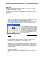
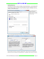
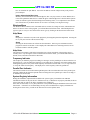
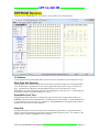
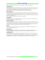
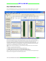
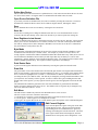
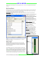
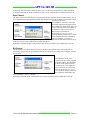
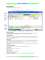
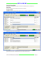
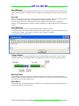
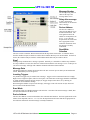
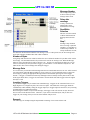
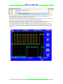
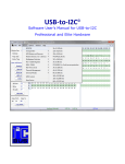
LPT-to-I2C SE Software User’s Manual LPT-to-I2C SE Information provided in this document is solely for use with LPT-to-I2C SE Professional. SB Solutions, Inc. reserves the right to make changes or improvements to this document at any time without notice. We assume no liability whatsoever in the sale or use of this product, including infringement of any patent or copyright. No part of this document may be reproduced or transmitted in any form or by any means, electronic or mechanical, for any purpose, without the express written permission of SB Solutions, Inc. Microsoft and Windows are registered trademarks of Microsoft Corporation. Other brand names are trademarks or registered trademarks of their respective owners. Questions or comments regarding this document should be emailed to [email protected] 2008 SB Solutions, Inc. All rights reserved. LPT-to-I2C SE Software User’s Manual Page 2 LPT-to-I2C SE Table of Contents I²C PROTOCOL .......................................................................................................................................... 6 GENERAL CHARACTERISTICS .......................................................................................................................... 6 BIT TRANSFER ............................................................................................................................................ 6 START AND STOP CONDITIONS ..................................................................................................................... 6 I²C ADDRESS ............................................................................................................................................. 6 I²C BUS DOCUMENTATION ........................................................................................................................... 7 MAIN SCREEN .......................................................................................................................................... 8 Device Menu .......................................................................................................................................... 8 Message Panel ....................................................................................................................................... 8 Messages: .............................................................................................................................................. 8 File Menu ............................................................................................................................................... 8 Save Data ............................................................................................................................................... 9 Load Data............................................................................................................................................... 9 Options Menu ........................................................................................................................................ 9 I²C Frequency Menu Item ...................................................................................................................... 9 Calibration Menu Item .......................................................................................................................... 9 Parallel Port Selection Menu Item ......................................................................................................... 9 Add Ports Menu Item .......................................................................................................................... 10 Ignore Acknowledge Menu Item ......................................................................................................... 11 Windows Menu ................................................................................................................................... 11 Help Menu ........................................................................................................................................... 11 Help ..................................................................................................................................................... 11 About ................................................................................................................................................... 11 Help Hints ............................................................................................................................................ 11 Frequency Indicator............................................................................................................................. 11 Parallel Port Indicator .......................................................................................................................... 11 System Registry Information ............................................................................................................... 11 EEPROM DEVICES ................................................................................................................................... 12 I²C Address........................................................................................................................................... 12 Write Page Size Selection .................................................................................................................... 12 Erase/Write Cycle Time ....................................................................................................................... 12 Data Grid.............................................................................................................................................. 12 Byte Address (Subaddress) .................................................................................................................. 13 Read Byte Button ................................................................................................................................. 13 Read All Button .................................................................................................................................... 13 Write Byte Button ................................................................................................................................ 13 Write All Button ................................................................................................................................... 13 Verify Button ....................................................................................................................................... 13 Fill Buffer ............................................................................................................................................. 14 Checkerboard ...................................................................................................................................... 14 Inverted Checkerboard ........................................................................................................................ 14 Goto Byte... .......................................................................................................................................... 14 Copy Block ........................................................................................................................................... 15 UNIVERSAL MODES ................................................................................................................................ 16 UNIVERSAL TRANSMITTER/RECEIVER ............................................................................................................ 16 Progress Bar ......................................................................................................................................... 16 Single Button ....................................................................................................................................... 17 LPT-to-I2C SE Software User’s Manual Page 3 LPT-to-I2C SE Repeat Button ..................................................................................................................................... 17 Stop Button.......................................................................................................................................... 17 Sequence Editor................................................................................................................................... 17 Delay .................................................................................................................................................... 17 Send Button ......................................................................................................................................... 17 Read/Write Bit ..................................................................................................................................... 17 USER DEFINABLE DEVICE .......................................................................................................................... 18 Define New Device .............................................................................................................................. 19 Open Device Definition File ................................................................................................................. 19 Save ..................................................................................................................................................... 19 Save As… .............................................................................................................................................. 19 Save Registers in text format ............................................................................................................... 19 Byte Mode ........................................................................................................................................... 19 Print Device Data ................................................................................................................................. 19 Data Grid.............................................................................................................................................. 19 Edit Menu ............................................................................................................................................ 19 Edit Current Register ........................................................................................................................... 19 Edit Current Device .............................................................................................................................. 20 Slider Control ....................................................................................................................................... 20 Spin Control ......................................................................................................................................... 21 Bit Control............................................................................................................................................ 21 EXPERT MODE ....................................................................................................................................... 22 Open New Page .................................................................................................................................... 22 Open Data File ...................................................................................................................................... 22 Save Data .............................................................................................................................................. 22 Close Expert Mode ............................................................................................................................... 22 Add a Row............................................................................................................................................. 22 Delete a Row ........................................................................................................................................ 22 Clear the current row ........................................................................................................................... 22 Copy the Current Row .......................................................................................................................... 23 Paste Data............................................................................................................................................. 23 Compress Data ..................................................................................................................................... 23 Send Message ....................................................................................................................................... 24 Send All ................................................................................................................................................. 24 Send Sequence ..................................................................................................................................... 24 Trigger Output ...................................................................................................................................... 24 Message Editor ..................................................................................................................................... 24 Write Mode .......................................................................................................................................... 24 Message Number ................................................................................................................................. 25 Delay after message ............................................................................................................................. 25 Device Address ..................................................................................................................................... 25 Read/Write Selection ........................................................................................................................... 25 Stop? ..................................................................................................................................................... 25 Message Data ....................................................................................................................................... 25 Inserting Triggers .................................................................................................................................. 25 Read Mode ........................................................................................................................................... 25 Device Address ..................................................................................................................................... 25 Message Number ................................................................................................................................. 26 Delay after message ............................................................................................................................. 26 Read/Write Selection ........................................................................................................................... 26 Stop? ..................................................................................................................................................... 26 Number of Bytes ................................................................................................................................... 26 Message Data ....................................................................................................................................... 26 LPT-to-I2C SE Software User’s Manual Page 4 LPT-to-I2C SE Inserting Triggers .................................................................................................................................. 26 Example ................................................................................................................................................ 26 LPT-to-I2C SE Software User’s Manual Page 5 LPT-to-I2C SE I²C Protocol General Characteristics The I²C protocol allows data to be transferred between devices using two open-drain (or open-collector) bidirectional lines. One line is the serial clock (SCL) and the other is the serial data (SDA). The bus master generates the Start conditions, the clock signals on SCL, as well as the Stop condition. An acknowledge is transmitted on the bus after each byte is sent over the bus. Bit Transfer Data on SDA must be stable while SCL is high. The state of SDA when SCL is high determines the logic level of the transmitted data bit. Start and STOP Conditions Within the procedure of the I²C bus, unique situations arise which are defined as START and STOP conditions. A HIGH to LOW transition on the SDA line while SCL is HIGH is one such unique case. This situation indicates a START condition. A LOW to HIGH transition on the SDA line while SCL is HIGH defines a STOP condition. The master always generates START and STOP conditions. The bus is considered to be busy after the START condition. The bus is considered to be free again a certain time after the STOP condition. I²C Address The first seven bits of an I²C transmission make up the slave address. The eighth bit (or the least significant bit) is the R/W bit that determines the direction of the message. A '0' in the least significant position of the first byte means that the master will WRITE information to the selected slave. A '0' in this position means that the master will READ information from the slave. When an I²C address is sent, each device in a system compares the first seven bits after the START condition with its own address. If they match, the device considers itself addressed by the master as a slave- LPT-to-I2C SE Software User’s Manual Page 6 LPT-to-I2C SE receiver or slave-transmitter, depending on the R/W bit. When selecting addresses within LPT-to-I2C SE, the software assumes the least significant bit is zero (write). If the I²C message is a write transmission, the least significant bit will be sent as a ‘0’ while if it is a read, the software will append a ‘1’ in the LSB position. I²C Bus Documentation The complete I²C Bus specification can be found at http://www.nxp.com/products/interface_control/i2c/index.html LPT-to-I2C SE Software User’s Manual Page 7 LPT-to-I2C SE Main Screen When the LPT-to-I2C SE program starts, a screen, as shown below, will be displayed on the monitor. Device Menu The device menu contains a list of I²C devices supported by the LPT-to-I2C SE software. Selecting the device from this menu may start any of the listed devices. You can have any combination of devices open at one time. Switching between active devices may be accomplished via the Window menu on the main toolbar. Device Menu Options Menu I²C Frequency Indicator Parallel Port Indicator Message Panel Help Hints Message Panel The main screen has a panel that displays messages from the program. It will indicate if the I²C transmission was successful or if there was a problem encountered. A list of messages is shown below. Messages: Transmission successful - the last I²C transmission was successfully completed. Address not acknowledged - an I²C address was successfully transmitted but no slave device acknowledged the address. A STOP condition is sent after the acknowledge clock pulse if no acknowledge is received. Data not acknowledged - an I²C address was previously acknowledged but one of the following data bytes was not acknowledged. . A STOP condition is sent after the acknowledge clock pulse if no acknowledge is received. Read acknowledged corrupted - the master tried to send a NACK (no acknowledge) for the last read byte in a transmission, but it was corrupted by a low level on SDA by another device on the bus. SDA stuck low - before a START condition is initiated, the software verifies that both the SDA and SCL lines are high. If SDA is stuck low, then an SDA stuck low message will be displayed. SCL stuck low - before a START condition is initiated, the software verifies that both the SDA and SCL lines are high. If SCL is stuck low, then an SCL stuck low message will be displayed. Hardware not detected- when the LPT-to-I2C SE software is first started; it verifies that the LPT-to-I2C SE hardware exists at LPT1. If it is not found at LPT1, it will check LPT2, and then LPT3. Detection is terminated when LPT-to-I2C SE hardware is found. The user may manually select a different port from the one selected by the program but LPT-to-I2C SE will again verify that hardware is available at the selected parallel port. The software will not attempt to proceed with any transmissions until the hardware has been detected. File Menu Upon starting the LPT-to-I2C SE software, the File menu contains the Exit and Close commands. When a device has been selected from the Device Menu, it is possible that the File Menu will also display device LPT-to-I2C SE Software User’s Manual Page 8 LPT-to-I2C SE specific commands such as Save As and Load. In User Device mode, previously created device files may be conveniently loaded. Save Data Many devices contain the menu item 'Save Data' under the File menu. The data may be recalled by selecting the Load Data item under the File Menu. Load Data After data has been stored using the 'Save Data' item in the File menu, it can be recalled by selecting the Load Data item. Options Menu The options menu allows you to change the I²C frequency and to choose the parallel port you will use to communicate with the I²C hardware. I²C Frequency Menu Item The Options Menu contains an item labeled ‘I²C Frequency’. By choosing this menu item, you will activate a dialog box, which shows the current I²C frequency and the maximum I²C clock speed available on the current parallel port. The speed/type of processor, as well as the chipset, used in your computer and the mode (‘Slow’ or ‘Normal’) determines the maximum frequency. Pressing the OK button will close the dialog box and will update the I²C frequency panel on the main screen. The frequency information will be stored in the Registry and will be recalled when the program starts again at a later time. You can expect bit rates up to 80 kHz with a Pentium class computer, however, many factors influence the maximum bit rate and your results may vary significantly. Many I²C devices are not designed to operate at frequencies above 100 kHz and may cause communication errors if operated beyond 100 kHz. Lower I²C frequencies may be needed for long cable runs or excessive bus capacitance situations. We have tested the software using the LPT-to-I2C SE hardware at the end of printer cables, as long as 25 feet, however, your results may vary. Although the accuracy of the I²C clock frequency measurement is typically better than ±5%, it is up to the user to verify the actual clock frequency. The frequency shown assumes no clock stretching or long rise times. The I²C clock frequency cannot be guaranteed. Calibration Menu Item When LPT-to-I2C SE is first started, it will attempt to calibrate the parallel port. Calibration is also performed when a new parallel port is selected or when changing between the 'Slow' and 'Normal' modes. This calibration is generally accurate to within ±5%; however, if the frequency is not as accurate as desired, try selecting the 'Calibrate' item in the Options menu again. Parallel Port Selection Menu Item The Options menu contains a list of three potential parallel port selections: LPT1, LPT2, and LPT3. The parallel port's address is listed beside the port name (for example: LPT1: 0378h). Only available ports will be listed as selectable. Parallel ports, which are not available, will be disabled (gray). Therefore, if you only have one parallel port in your computer, you will not have the ability to switch to a different parallel port. When the program starts, it scans the available ports for the I²C hardware. The user is notified if it cannot be found, otherwise, the when it is found, the selected parallel port will have a check mark placed beside it in the Options menu. When a new parallel port is selected from the Options menu, the change takes effect immediately. The selected port will also be displayed in the Parallel Port Indicator in the lower right corner of the screen. LPT-to-I2C SE Software User’s Manual Page 9 LPT-to-I2C SE Add Ports Menu Item The Options menu contains a selection for adding a non-standard parallel port. A non-standard parallel port is generally a port that is contained on a PCI-based add-in card. Before attempting to add a port, you need to find the address of the port. This can be found in the Windows Control Panel. Here is an example of a non-standard LPT port: As you can see here, the LPT port is found at address 0x9F00. Note this address before proceeding to the next step. Now, go to the Options menu and select Add Ports. LPT-to-I2C SE will display the following: Enter the address into the box, then press the Add port button. The port will now be available in the Options menu, and it will behave like a standard LPT port. The address will be saved so you will not LPT-to-I2C SE Software User’s Manual Page 10 LPT-to-I2C SE have to remember the port address. Just select the address from the Add previously used port and press Add port. Ignore Acknowledge Menu Item Normally, the software checks the acknowledge bit, after every byte written, to ensure that the slavereceiver has pulled the SDA line low. When the Ignore Acknowledge item is checked in the Options menu, the software ignores the acknowledge bit state during writes, so it is important to note that the user will not have any feedback whether or not a device is actually receiving the message. Windows Menu The Windows Menu contains screen commands such as cascade, tile, arrange all icons, and minimize all. If there are devices active in the program, you will find them listed in this menu. When multiple device types are open, it is easy to move between the device types by clicking on the desired item in this menu. Help Menu Help Help may be activated at any time in the program by choosing Help from the Help Menu. Pressing the F1 key may also activate context-sensitive help. About Selecting the About menu item will activate the About Box. This box gives information such as program revision level and date. It also displays the email address for contacting i2ctools.com for technical assistance with this product. Help Hints The main screen contains a panel at the bottom that gives a short description of the item the cursor is currently above. By moving the cursor around the screen with the mouse, you will find that almost all buttons, boxes, and other controls have these hints. Frequency Indicator The frequency at which the program is sending I²C messages over the parallel port is shown in this box on the main screen. You can change the frequency by activating the I²C Frequency item in the Options menu. Although the typical accuracy of the clock frequency measurement is better than +/-5%, it is up to the user to verify the actual clock frequency. The displayed I²C clock frequency cannot be guaranteed. Parallel Port Indicator The main screen has an area in the bottom right hand part of the screen that shows the active parallel port. Selecting a different port from the Options menu can change the active parallel port. This box is empty if no hardware has been found. System Registry Information During the installation, important data is added to the system registry for Windows NT/2000/XP installations in order for the port driver to function correctly. If this data is not properly installed, the driver will not start and you will not be able to send data to the parallel port. If the data was not found, it is very likely that there was a problem during the installation of the LPT-to-I2C SE software. If the driver is not functioning correctly, due to invalid/incorrect registry information or missing device driver files, you will not be allowed to access the Options menu. LPT-to-I2C SE Software User’s Manual Page 11 LPT-to-I2C SE EEPROM Devices Upon starting any EEPROM device, you will see a screen similar to the one shown below. I²C Address A drop-down menu is provided which allows the user to select a valid address for the selected device type. Write Page Size Selection The Page Write Size defines the number of bytes that may be written in a single erase/write programming cycle. Smaller devices generally use an 8 or 16-byte pages while larger devices use up to 128 bytes per page. Check the device datasheet to find the appropriate page write size for the device you are programming. If you do not know the page size, use a small page size such as 8 bytes. A smaller page size will require a longer total programming time for a device. Erase/Write Cycle Time Programming software must allow a certain period of time to elapse after writing a block of data to an EEPROM. This time is device dependent but is normally between 5ms and 40ms. A STOP condition must be performed before the erase/write cycle commences. Most EEPROMs will not respond to their address until the erase/write cycle has been completed. Data Grid The data grid consists of rows and columns. Each cell within the grid contains a two digit hexadecimal number. Each cell corresponds to a physical byte location within the memory device. For example, in the diagram below, cell 0x21 is highlighted (row 2, column 1). LPT-to-I2C SE Software User’s Manual Page 12 LPT-to-I2C SE This translates to address 33 (decimal) in the device. The program calculates the physical address for you and displays it at the left side of the screen in the box labeled ‘Word Address’ or ‘Subaddress’. Byte Address (Subaddress) The byte address (sometimes called subaddress or word address) is a pointer to a register or memory location within the I²C device. To access this location, the software will send out the device I²C address, followed by this byte address, followed by the read or write data. The program displays the byte address of the active cell of the memory grid in both hexadecimal and decimal notation. Read Byte Button Pressing the 'Read Byte' button initiates a read from the I²C device. The program begins the transmission by writing the device address, followed by the current byte address. A Repeated Start is then generated, followed by the device’s read address, and finally a read of a single data byte. The result of each byte read is immediately entered in the appropriate cell in the grid. Alternatively, you may press the <Alt> and <b> keys simultaneously to achieve the same results. Read All Button Pressing the 'Read All' button initiates a read from the I²C device. The program begins the transmission by writing the device address, then the byte address 0x00. A Repeated Start is then generated, followed by sequential reads of the entire device. In addition to pressing the 'Read All' button, you may press the <Alt> and <r> keys simultaneously to achieve the same results. Write Byte Button Pressing the 'Write Byte' button initiates a Write to the I²C device. The program begins the transmission by writing the slave address and then the word address of the currently active cell in the grid. The selected data byte is then sent. In addition to pressing the 'Write Byte' button, you may press the <Alt> and <y> keys simultaneously and achieve the same results. Write All Button Pressing the 'Write All' button initiates a Write to the I²C device. The program begins the transmission by writing the byte address 0x00 to the device and sequentially writes the entire device. For a RAM type device, the data is sent in one long message. In the case of an EEPROM, the software will send one page of data (usually 8 bytes but check the datasheet for the particular device you are addressing) followed by a STOP condition. Following the STOP condition, the program waits a length of time, determined by the Erase/Write cycle time of the device (again check the datasheet for the device you are programming), before writing another page to the device. In addition to pressing the 'Write All' button, you may press the <Alt> and <w> keys simultaneously to achieve the same results. After the completion of the write cycle, LPT-to-I2C SE will read the entire device to verify that the contents of the device match the data that was sent. An error message will be displayed if the data read from the device does not match the data in the on-screen buffer. Verify Button Pressing the ‘Verify’ button initiates a read of the entire EEPROM. After reading the contents of the EEPROM, LPT-to-I2C SE will compare the contents with the values in the grid. An error will be flagged if the contents of the EEPROM do not match the contents of the LPT-to-I2C SE on-screen grid. LPT-to-I2C SE Software User’s Manual Page 13 LPT-to-I2C SE Fill Buffer The grid will be filled with the two digit hexadecimal number found in the ‘Fill with’ edit box when the Fill Buffer button is pressed. The fill can be constrained to the addresses found in the ‘Fill from’ to the ‘Fill to’ edit boxes. No information will be sent over the I²C bus. Checkerboard The grid will be filled an alternating ‘1’ and ‘0’ pattern when this is chosen from the Fill with Checkerboard selection is made on the Edit menu. Inverted Checkerboard The grid will be filled an alternating ‘0’ and ‘1’ pattern when this is chosen from the Fill with Inverted Checkerboard selection is made on the Edit menu. Goto Byte... When the Go To Byte selection is made from the Edit menu, a dialog box is displayed where a hex or decimal address may be entered. When the OK button is pressed the grid location with the desired address is shown. This is useful when you don’t want to scroll through to find a specific data location. LPT-to-I2C SE Software User’s Manual Page 14 LPT-to-I2C SE Copy Block It is possible to copy a block of data from one on-screen buffer area to another using the Copy Block function. Simply define the data to be copied using the ‘Copy From’ edit boxes and then enter the address where the data is to be copied to. The ending address is calculated automatically by the software and is not editable by the user. Pressing the Copy Block button starts the copying process. LPT-to-I2C SE Software User’s Manual Page 15 LPT-to-I2C SE Universal Modes Universal Transmitter/Receiver The figure below shows the screen of the Universal I²C Transmitter/Receiver. Each I²C Message (dataset) contains an address + R/W bit and a maximum of 22 data bytes. The data bytes are shown as two digit hexadecimal numbers. Only valid hexadecimal numbers can be entered into each box. Non-hexadecimal keyboard entries will be ignored with the following exceptions: INSERT key - pressing this key adds an extra edit box to the Message. The maximum number of data bytes is 16, so the INSERT key will be ignored if there are already 16 bytes present. DELETE key - pressing this key deletes the data byte where the cursor presently is shown. The software requires that you keep at least one data byte in the Message. It will also not let you delete the address byte or R/W bit following a restart. If you want to delete a restart, make sure the cursor is in the Start box and then press the DELETE key. S (Restart) key - a restart condition may be inserted into any Message location by pressing the S key on your keyboard. The software deletes the boxes after the repeated start condition and then inserts 'S00WFF'. An example of a message with a restart condition is shown below. R (Read) key - is a read condition. This may be changed to a write condition by pressing the ‘w’ key. W (Write) key - is a write condition. This may be changed to a read condition by pressing the ‘r’ key Progress Bar The progress bar is visible when the Repeat sequence button is pressed and is invisible when the LPT-to-I2C SE Software User’s Manual Page 16 LPT-to-I2C SE transmission has stopped. It is used as a visual cue that there is a transmission underway. Single Button Pressing the Single Button starts the transmission of I²C messages shown in the Sequence editor box. After the last message in the Sequence Editor box has been transmitted, the I²C transmissions are terminated. A delay is inserted between each I²C message if the Delay box is greater than zero. The transmission is terminated with a Stop condition as soon as an error is encountered. Repeat Button Pressing the Repeat Button starts the transmission of messages shown in the Sequence editor box. After the last I²C message in the Sequence Editor box is transmitted, the I²C transmissions are started once again with the first message shown in the Sequence Editor box. A delay is inserted between each message if the Delay box is greater than zero. The transmission is terminated as soon as an error is encountered. Stop Button Pressing the Stop button will terminate a Repeat Sequence. However, LPT-to-I2C SE will complete the entire sequence before the I²C transmission ends. Sequence Editor The user changes the sequence editor to reflect the order in which the I²C messages will be sent via the I²C bus. The sequence editor allows from 1 to 10 digits to be entered. Only digits 1,2,3,4, and 5 are allowed in the box since there are only 5 messages. For example, if you entered 35123441 into the sequence editor box, message 3 will be sent, followed by message 5, followed by message 1, etc. Delay A delay can be inserted between messages by increasing the value of the number in the Delay box. The number is measured in milliseconds. Send Button Pressing the Send Button will send the currently active message. Clicking in any edit box, in the desired message, will change the active message. The active message is shown above the send button. Read/Write Bit The Read/Write bit determines whether the I²C message will read or write to a device via the I²C bus. If this box is an R, then the address byte will end with a logic ‘1’. If this box is a ‘W’, then the address byte will end with a logic ‘0’. An ‘R’ (read) will be changed to write by pressing the ‘w’ key, while a ‘W’ will be changed to ‘R’ by pressing the ‘r’ key. All key presses other than ‘r’ and ‘w’ will be ignored. LPT-to-I2C SE Software User’s Manual Page 17 LPT-to-I2C SE User Definable Device The User Definable Device allows you to define your own I²C device and then enables the user to change the values of the individual cells within the grid using various controls such as sliders and spin controls. When the User Definable Device is first opened, a 256 byte device grid is shown on the screen but does not have any names associated with the data, and all the data bytes are set to 0xFF. A previously defined device may be loaded by selecting it from the Most Recently Used files at the bottom of the File menu. If devices have not yet been defined, there will be no devices shown below the File/Exit menu item. To begin the definition process, you may right click with your mouse on any data cell in the grid or select 'Current Device' or 'Current Cell' from the Edit menu. The Reset item in the Edit menu will clear all the register names to 'Undefined Register' and set the data values to 0xFF. Clicking on the desired cell and doing one of the following can change the data value of the individual cells: 1. Typing in a two digit hexadecimal number. 2. Assigning a slider to the active cell by pressing the Slider button. 3. Assigning a spin control to the active cell by pressing the Spinner button. 4. Assigning a Bit-wise control to the active cell by pressing the Bit-wise button. Items 2, 3, and 4 can also be achieved by positioning the cursor over the desired cell and right clicking on the grid to select the appropriate control from the pop-up menu. LPT-to-I2C SE Software User’s Manual Page 18 LPT-to-I2C SE Define New Device This is similar to the Edit Current Device (explained below). This menu selection allows the user to start a new device from scratch. All register names are undefined and all default values are 0xFF. Open Device Definition File A previously saved device definition file (.def) can be recalled by selecting this menu item. The device definition file contains the Device Name, Device Address, Register Names, and Register Values. Save Device definition files can be saved to disk by selecting the Save menu item. Save As… Use the Save As dialog box to change the definition file name or to save the definition file in a new location. If the file name already exists, LPT-to-I2C SE asks if you want to replace the existing file. Save Registers in text format The device definition files are not in a format that can easily be used by the user, therefore, LPT-to-I2C SE allows you to save the information in a text format (extension .txt). The user can then open and edit this file with any word processor such as Notepad or WordPad. The text files are for the user’s information only and cannot be read by LPT-to-I2C SE. Byte Mode When the Write All and Read All buttons are pressed, the software assumes that the subaddress is autoincremented after each data byte is written or read. For example, if you have a four byte device, the writing sequence would be Start-Address-Subaddress0-data0-data1-data2-data3-Stop. Many devices do not auto-increment the subaddress between data bytes and require that only one data byte is sent for each transmission. In these situations, click on the Byte Mode check box. The writing sequence would be StartAddress-Subaddress0-data0-Stop. The sequence would be repeated for each data byte. Print Device Data A print out of the register definitions can be obtained by selecting this option from the File menu. Data Grid The grid consists of rows and columns. Each cell within the grid contains a two digit hexadecimal number. Each cell corresponds to a physical byte location within the I²C device. For example, in the diagram shown above, cell 0x07 is highlighted (row 0, column 7). This translates to address 7 (decimal) in the device (assuming the first byte is address 0x00). The data may be changed by entering hexadecimal numbers from your keyboard. Non-valid keys will be ignored. In order to edit the entire grid, including the name and default values of the registers, you may right click on the grid or select the appropriate item from the Edit menu. The individual cells within the grid will be blue if the cell's subaddress is greater than the maximum number of registers defined for the active device. The number of device registers may be changed at any time in the ‘Edit Current Device’ screen. Edit Menu The Edit menu is available only when the User Definable Device screen is active. The user can select from one of the three menu items: 1. Current Device - brings up a screen showing the all the register data for the active device. 2. Current register - allows registers to be changed one at a time. 3. Reset grid - all register data will be set to 0xFF and the register descriptions will be 'Undefined Register' Edit Current Register If you want to adjust one register in the grid, use the 'Edit Current Register' screen. This screen can be started by right clicking on the User Definable Device grid or by selecting Current Register from the Edit menu. The name of the register and the initial value displayed, when the definition file is first opened, can be changed here. Note LPT-to-I2C SE Software User’s Manual Page 19 LPT-to-I2C SE that the register name changes are not saved until the ‘Save’ or ‘Save As..’ item (under the File menu) is selected. Edit Current Device Editing the current device may be accomplished by clicking on 'Edit Current Device' from the Edit menu, or by right clicking on the grid within the User Definable Device mode of LPT-to-I2C SE. The screen, shown above will be displayed when either method is invoked. Device Name: the name entered in this box will be shown in the title bar of LPT-to-I2C SE when the definition file is opened. Device Address: is the device I²C address that will be displayed in the Address box when the definition file is opened. Note that only even addresses are valid here. LPT-to-I2C SE will append the appropriate R/W bit at the end of the address depending upon the operation to be performed (the last bit will be a '1' if it is a read operation and a '0' if it is a write). Number of Registers: Enter the number of registers the device contains. The size of the data entry grid will be modified to accommodate the number of registers. Fill: This box should be modified only if you want to initialize all the registers to one particular value. OK button: the data entered by the user in the 'Edit Current Device' screen will be transferred to the User Definable Device screen. Cancel button: the editing session will be closed and no changes to the User Definable Device screen will occur. Note that any changes are not saved until the ‘Save’ or ‘Save As…’ menu item is selected. Slider Control The Slider Control is activated when the user presses the Slider button on the User Defined Device screen or by right clicking the grid and then selecting 'Change Active Register with Slider Control' from the pop-up menu. The subaddress of the active cell in the grid will be assigned to the Slider. The subaddress is shown in the upper left corner. Moving the slider bar up and down will cause the value of that cell to be changed. If Auto Write On is checked, then the contents of the cell will be transmitted to the device subaddress when it is changed. If an error is encountered while transmitting using Auto Write, LPT-to-I2C SE LPT-to-I2C SE Software User’s Manual Page 20 LPT-to-I2C SE will turn off Auto Write and it will be up to the user to fix the error condition and re-enable Auto Write. It should be noted that the Slider Control always stays on top of all other devices within LPT-to-I2C SE. Spin Control The Spin Control is activated when the user presses the Spinner button on the User Defined Device screen or by right clicking the grid and then selecting 'Increment/Decrement Current Register with a Spin Control' from the pop-up menu. The subaddress of the active cell in the grid will be assigned to the Spin Control. The subaddress is shown in the upper left corner. Clicking on the spin control's up or down arrow will cause the value of that cell to be incremented or decremented. If Auto Write On is checked, then the contents of the cell will be transmitted to the device subaddress when it is changed. . If an error is encountered while transmitting using Auto Write, LPT-to-I2C SE will turn off Auto Write and it will be up to the user to fix the error condition and re-enable Auto Write. It should be noted that the Spin Control always stays on top of all other devices within LPT-to-I2C SE. Bit Control The Bit Control is activated when the user presses the Bit Control button on the User Defined Device screen or by right clicking the grid and then selecting 'Use Bit Control to Change Active Register' from the pop-up menu. The subaddress of the active register in the grid will be assigned to the Bit Control. The subaddress is shown in the upper left corner. Clicking on any of the eight edit boxes will cause the value of that bit to be inverted. If Auto Write On is checked, then the contents of the cell will be transmitted to the device subaddress when it is changed. It should be noted that the Bit Control always stays on top of all other devices within LPT-to-I2C SE. LPT-to-I2C SE Software User’s Manual Page 21 LPT-to-I2C SE Expert Mode The figure below shows the Expert Mode screen. Open New Page Pressing this button opens a new blank page. There will be 32 empty rows (messages). Selecting ‘New’ from the ‘File’ menu while the Expert Mode is active will perform the same function. Open Data File A previously saved data file can be recalled by pressing the Open Data File button or by selecting Open from the File menu while the Expert Mode is active. A dialog box will be displayed allowing the user to navigate to the appropriate directory. Save Data The current data will be saved when this button is pressed. The user specifies the name and location of the file in a dialog box that is displayed after the button is pressed. A dialog box will be displayed which allows the user to navigate to the appropriate directory. The user can also perform the same function by selecting Save from the File menu while the Expert Mode screen is active. Close Expert Mode The Expert Mode screen is closed but LPT-to-I2C SE will not be terminated. Add a Row Inserts a new (blank) row after the current row. Delete a Row Deletes the current row (current message). Clear the current row The current row (message) will be cleared. The row will not be deleted but will appear blank. LPT-to-I2C SE Software User’s Manual Page 22 LPT-to-I2C SE Copy the Current Row The current row (message) will be copied. Use the Paste command to paste it to a different row. Paste Data Previously copied data will be pasted into the current row (message). Compress Data All blank rows will be eliminated from the display. Here is an example of a display before compress: And here is the same screen after the compress: It is not required to perform a compress but it does speed up the message transfer process since the application does not need to evaluate blank rows to see if there is data to be sent. LPT-to-I2C SE Software User’s Manual Page 23 LPT-to-I2C SE Send Message The current message will be sent when this button is pressed. The current message number is shown below the Send Message button. To change the active message to be sent, single-click on the row of the data to be sent. Send All All the valid messages on the screen will be sent in order of the row number. The action will be performed one time. A message is valid if there is a minimum of an address within the message. Since the program tests for a valid message on each line within the message grid before sending the message, it is recommended (not required) to compress the data (see Compress Data above) to speed up the transfer. Send Sequence A sequence of messages will be sent when the Send Sequence button is pressed. The sequence editor is invoked by double-clicking on the sequence display. The sequence length can be up to 64 messages in length. The sequencer is limited to using messages 1 through 99. The Sequence Editor is shown below. Trigger Output The Trigger Output can be toggled high and low by pressing the buttons on the toolbar. This is useful for setting the initial value of the Trigger output. The Input pin state can also be read by pressing the button. Message Editor The i2c message cannot be edited directly in the Expert mode screen. Instead, an Expert Mode Editor is brought up either by double-clicking on a message or when the user attempts to type directly into one of the rows (messages) in the Expert Mode screen. Write Mode The message editor for a Write transaction is shown below. Note that if the current message is blank, then the editor will default to the Write mode. LPT-to-I2C SE Software User’s Manual Page 24 LPT-to-I2C SE Message Number The message being edited is shown at the top of the message editor screen. Delay after message A delay, measured in milliseconds, can be inserted after a message. Device Address The I2C slave address is entered in the address box in hexadecimal notation. The least significant bit of the address is not important (can be a ‘1’ or ‘0’) since the Expert Mode will ensure that this is appropriate for the read/write transaction when the message is actually transmitted. Read/Write Selection The user can select a Read or Write transaction from the drop-down selection box. If a Read is chosen, then the ‘Number of Bytes to Read’ box will be shown and the data entry area will be hidden. If a Write is chosen, the ‘Number of Bytes to Read’ will be hidden and the data entry area will be shown. Stop? Sending a Stop condition after a message is optional. Normally, it is advisable to send the Stop condition. If a Stop condition is not sent, the clock line will be held low until the next message is sent. If a Stop is not sent, the next message will begin with a Restart condition rather than a Start condition. Message Data The Message Data area contains the location where the user can enter up to 64 data bytes in hexadecimal format. Blank data bytes will be ignored. Inserting Triggers Any number of triggers may be inserted into a message. Triggers can be a transition from Low-to-High, High-to-Low, a high-level pulse, and a low-level pulse. The initial state of the trigger should be established by either manually setting the Trigger Output (see Trigger Output section above) or by inserting an initialization level within the message. When setting the Number of Bytes in the message, each trigger event will count as one byte but it will have no effect on the SDA/SCL lines. Read Mode The message editor for a Read transaction is shown below. Note that if the current message is blank, then the editor will default to the Write mode. Device Address The I2C slave address is entered in the address box in hexadecimal notation. The least significant bit of the address is not important (can be a ‘1’ or ‘0’) since the Expert Mode will ensure that this is appropriate for the read/write transaction when the message is actually transmitted. LPT-to-I2C SE Software User’s Manual Page 25 LPT-to-I2C SE Message Number The message being edited is shown at the top of the message editor screen. Delay after message A delay, measured in milliseconds, can be inserted after a message. Read/Write Selection The user can select a Read or Write transaction from the drop-down selection box. Stop? Sending a Stop condition after a message is optional. Normally, it is advisable to send the Stop condition. If a Stop condition is not sent, the clock line will be held low until the next message is sent. If a Stop is not sent, the next message will begin with a Restart condition rather than a Start condition. Number of Bytes Using the up and down arrows in this box allows the user to define the number of bytes that will be read in the message. The maximum number of bytes that can be read in one message is 64. When the Message Editor is closed, the unread bytes will be shown as ‘FF’. Triggers are considered one data byte so if you want to read 8 data bytes and you need a Trigger; you will choose ‘9’ in the Number of Bytes box. The SDA and SCL lines will not change state during the Trigger. Message Data It is not necessary to enter data in the Message Data area in a Read transaction since an ‘FF’ will be entered into each location when the Message Editor is closed. However, you can optionally insert a Trigger into the message by clicking the appropriate Message Data location and then pressing one of the Trigger buttons. A Trigger is considered one data byte although it doesn’t actually send any data on the i2c bus. In the figure shown above, a trigger was inserted at a location which will send a trigger before the eighth data byte is read. Inserting Triggers Any number of triggers may be inserted into a Read message. Triggers can be a transition from Low-toHigh, High-to-Low, a high-level pulse, and a low-level pulse. The initial state of the trigger should be established by either manually setting the Trigger Output (see Trigger Output section above) or by inserting an initialization level within the message. When setting the Number of Bytes in the message, each trigger event will count as one byte but it will have no effect on the SDA/SCL lines. Therefore, if you want to read 8 data bytes, and you have two triggers in your message, then you need to set the Number of Bytes to 10. Example The following is an example using the Expert Mode consisting of two writes and one read. LPT-to-I2C SE Software User’s Manual Page 26 LPT-to-I2C SE The first message shows a write to the LPT-to-I2C SE Hardware Adapter’s on-board eeprom. This will write eight data bytes starting at subaddress 0x00. Ten bytes will be sent in total (Address [A0] + subaddress [00] + eight data bytes [00,01,02,03,04,05,06,07]). The second message is a write to the eeprom setting the subaddress to 0x00. There is no Stop at this end of this message. Two bytes will be sent in total (Address [A0] + subaddress [00]). The third message begins with a Restart condition since there was no Stop at the end of Message 2. A read will consist of eight data bytes with a Trigger (PL=Pulse Low) before the last byte is read. If the Trigger output of the Hardware Adapter was connected to the External Trigger of an oscilloscope, you would see the trace shown below. The trace shows that the scope was triggered just before the last byte was read. The trace clearly shows that the last data byte is 0x07, followed by a NACK, then a Stop condition. LPT-to-I2C SE Software User’s Manual Page 27