1
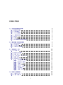
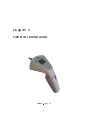
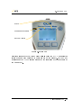
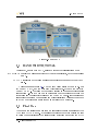
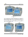
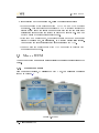
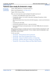
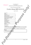
MPB S.r.l.
Tel +39 0641200744
Via Giacomo Peroni 400/402
Fax +39 0641200653
00131 ROMA (RM)
[email protected]
www.gruppompb.com
User Manual
CCM
Contact Current
Meter
Updated to Firmware Version:
CCM V1.03
SAFETY NOTES
Read carefully before using the product
MPB works to provide to its customers the best safety conditions available complying with the current safety standards. The instrumentation described in this
manual has been produced, tested and left the factory in conditions that fully
comply the European standards.
To maintain it in safe conditions and ensure
the correct use, these general instructions must be fully understood and applied
before using the product.
This product is designed for industrial environment and laboratories and
should be used by skilled sta only. MPB disclaims responsibility for a dierent
use of the device.
Use the device only after checking the presence and validity of the
safety devices (as breakers, dierential switches and the validity of
grounding)
For safety reason, the
the
HAND measure modality has to be done only after
GROUND PLANE modality which marks a value below regulations limits
dened by the 2013/35/EU regulation.
II - User Manual CCM
Declaration of Conformity
(in accordance with the Directives: EMC 89/336/EEC and Low Voltage 73/23/EEC)
This is to certify that the product: CCM
(Contact Current Meter)
complies with the following European Standards:
Safety: CEI EN 61010-1 (2001)
EMC: EN 61326-1 (2007)
This product complies with the requirements of the Low Voltage Directive
2006/95/CE, and with the EMC Directive 2004/108/CE.
MPB S.r.l.
User Manual CCM - III
IV - User Manual CCM
Contents
1
2
3
4
General Information
1
1.1
Introduction . . . . . . . . . . . . . . . . . . . . . . . . . . . . . .
2
1.2
Descrizione
. . . . . . . . . . . . . . . . . . . . . . . . . . . . . .
2
1.3
Composition . . . . . . . . . . . . . . . . . . . . . . . . . . . . . .
2
1.4
Optional Kit . . . . . . . . . . . . . . . . . . . . . . . . . . . . . .
2
1.5
Front . . . . . . . . . . . . . . . . . . . . . . . . . . . . . . . . . .
3
1.6
Rear
. . . . . . . . . . . . . . . . . . . . . . . . . . . . . . . . . .
4
1.7
Technical Specications . . . . . . . . . . . . . . . . . . . . . . . .
5
Principle of operation
7
2.1
Logic Schema
. . . . . . . . . . . . . . . . . . . . . . . . . . . . .
7
2.2
Measures . . . . . . . . . . . . . . . . . . . . . . . . . . . . . . . .
8
2.3
Contact Current . . . . . . . . . . . . . . . . . . . . . . . . . . . .
8
Usage of CCM
11
3.1
Switch On . . . . . . . . . . . . . . . . . . . . . . . . . . . . . . .
11
3.2
Standby Screen
. . . . . . . . . . . . . . . . . . . . . . . . . . . .
12
3.3
Hand or GP . . . . . . . . . . . . . . . . . . . . . . . . . . . . . .
12
3.4
BANDWIDTH/TOTAL
14
3.5
First Run
. . . . . . . . . . . . . . . . . . . . . . . . . . . . . . .
14
3.6
Menu of CCM . . . . . . . . . . . . . . . . . . . . . . . . . . . . .
16
3.6.1
Regulation limit . . . . . . . . . . . . . . . . . . . . . . . .
16
3.6.2
Beep on press . . . . . . . . . . . . . . . . . . . . . . . . .
17
3.6.3
Alarm
. . . . . . . . . . . . . . . . . . . . . . . . . . . . .
17
3.6.4
Auto OFF . . . . . . . . . . . . . . . . . . . . . . . . . . .
17
3.6.5
Date & Time
. . . . . . . . . . . . . . . . . . . . . . . . .
19
3.6.6
Contrast . . . . . . . . . . . . . . . . . . . . . . . . . . . .
19
3.6.7
Clear Data . . . . . . . . . . . . . . . . . . . . . . . . . . .
19
. . . . . . . . . . . . . . . . . . . . . . .
Data Download
4.1
Connect to PC
4.2
Data Format
21
. . . . . . . . . . . . . . . . . . . . . . . . . . . .
21
. . . . . . . . . . . . . . . . . . . . . . . . . . . . .
22
V
CONTENTS
Figures List
VI - User Manual CCM
25
Chapter 1
General Information
Figure 1.1: CCM
1
1. General Information
1.1 Introduction
CCM was designed to measure the contact current that may be generated when
you touch electrical / electronic equipment, which stays inside an radio frequency
eld, in a quickly and accurately way.
1.2 Descrizione
CCM (Figure 1.1) is a portable measuring device with more than one measure
mode.
Depending on yours need, it can measure by means of the
GROUND
PLANE (which is a standard impedance level), or it can works without cable,
exploiting the users impedance level through the conductive area on the handle.
In the next chapters we will see more deeply this subject.
1.3 Composition
The device come with its special suitcase, containing the GP (Ground Plane),
a ground wire and a standard resistance.
1.4 Optional Kit
CCM-Kit of calibration, made of:
•
CCM-JIG
•
standard resistance R45
•
RG316 cable (1 mt length) N(M)-sma(M)
2 - User Manual CCM
1. General Information
1.5 Front
In Figure 1.2 is showed the CCM front panel:
On/O switch
Micro USB connector
Keyboard
Figure 1.2: CCM front
User Manual CCM - 3
1. General Information
1.6 Rear
In Figure 1.3 is showed the CCM rear panel:
Measure Tip
Measure trigger
Ground connector
Figure 1.3: CCM rear
4 - User Manual CCM
1. General Information
1.7 Technical Specications
Frequency Range
Low band
Medium band
High band
Frequency Response
Low band
Medium band
High band
40 Hz to 2.5 kHz
2.5 kHz to 100 kHz
100 kHz to 110 MHz
<+
− 1 dB
<+
− 1.5 dB
<+
− 1.2 dB
Measurement range
Low Band
Level range
Damage level
Resolution
Dynamic range @ 500Hz
Linearity error @ 500Hz; 0,3...3 mA
Medium band
Level range
Damage level
Resolution
Dynamic range @ 10kHz
Linearity error @ 10Hz; 10...200 %
High band
Level range
Damage level
Resolution
Dynamic range @ 10MHz
Linearity error @ 10Mz; 12...120 mA
Measurement mode
Alarm sound
Display
Detectors
Contact tip
0.01 to 3 mA (ICNIRP limit 1 mA)
100 mA
1 nA
50 dB
<+
− 1 dB
0 to 300 % (ICNIRP limit 1 to 40 mA)
500 %
1 nA
50 dB
<+
− 1 dB
0.4 to 120 mA (ICNIRP limit 40 mA)
300 mA
10 nA
50 dB
<+
− 1 dB
Hand and Ground
Programmable level
Graphic LCD with led backlight
true RMS
Interchangeable
USB Interface
Micro USB connector
Standards
Directive 2004/40/EC
Operating Temperature
Power supply
+10 ◦ C to +40 ◦ C
Battery
Operation Time
2pcs AA Alkaline
24 hours
Dimension
205 × 90 × 45 mm
Weight
Recommended calibration interval
Input signal attenuation over 110 MHz
200 g
24 months
200 MHz > 7 dB
300 MHz > 18 dB
400 MHz > 31 dB
500 MHz ... 3 GHz > >45 dB
User Manual CCM - 5
1. General Information
6 - User Manual CCM
Chapter 2
Principle of operation
2.1 Logic Schema
The schema showed in Figure 2.1 describe CCM work ow:
Hand
Low
Band
Filter
true
RMS
detector
Display
Ground
Plane
Medium
Band
Filter
true
RMS
detector
A/D
µP
MEM
Tip
High
Band
Filter
true
RMS
detector
Figure 2.1: CCM Block Diagram
7
USB
2. Principle of operation
2.2 Measures
The CCM has a digital nature, but it can measure the true RMS (Root Mean
Square) value for all analog signals from 40Hz. The RMS value of a waveform
signal is equal to a DC current witch provides the same power to the load. The
signal is measured by the TIP and pass through the most suitable lter (Low,
Medium and High), then arrives at the true RMS detector who gets the value.
The equation is the following:
s
erms =
1
T
Z
T
V(t)2 dt
0
The actual regulations denes the minimum requirements for the safety of
workers and general public in areas of risk, and the limit values for exposure to
current contact.
2.3 Contact Current
The current contact happens when a electrical conductor touches another metallic
object immersed in an electromagnetic eld, and is expressed in Amperes. The
moment after the contact, can cause a discharge of currents associated (First
attachment of 2013/35/EU). In the workplace, as indeed in the world we live
in, the electric and magnetic elds are always present and may have natural or
articial origin. The natural electric elds are, for example, those produced by
the accumulation of electric charges during lightning, while the natural magnetic
elds are those that are found in nature, such as the terrestrial that orients the
compass needle North-South . The electric and magnetic elds are produced by
articial devices and systems, such as electrical equipment or systems for the
distribution of electricity.
The electromagnetic eld is dened as a physical phenomenon given by the
simultaneous existence of an electric eld and a magnetic eld.
Moving away
from the source of the electromagnetic eld, waves decrease in intensity, it is
therefore clear that the intensity is maximum if it comes in contact with the
object or with the system which is generating the electromagnetic eld. A device
with metallic shell if immersed in an electromagnetic eld can become a carrier
of RF voltage and electrical charge. If you come into contact with the said device
without adequate protection, you risk that the RF voltage discharge to ground
owing through the limbs and body. In this case the electrical charges present
on the device immersed in the electric eld through the operator's body have
generated a contact current. An electrical equipment not properly shielded can
emit electromagnetic waves. If it comes into contact with the above machinery
without adequate protection, even in this case there is a risk that electromagnetic
8 - User Manual CCM
2. Principle of operation
waves owing through the limbs and the operator's body to generate a contact
current.
User Manual CCM - 9
2. Principle of operation
10 - User Manual CCM
Chapter 3
Usage of CCM
3.1 Switch On
Release n◦
Figure 3.1: turned on CCM
When the CCM is turned on it shows the company logo and the rmware
version (Figure 3.1). After a few seconds a warning message will appear (as in
Figure 3.2), and users declare to have read this manual and be aware of the risks
involved during the current measurement. In case of negative answer (by pressing
DENY), the device will automatically turn o.
11
3. Usage of CCM
Figure 3.2: menu of CCM
Once you accept the terms of use, the device will remain in the state of
STANDBY until the operator presses the Trigger to make a measurement.
3.2 Standby Screen
In Figure 3.3 is showed the standby screen. Focusing the high part of display:
•
Battery indicator.
•
The
Measure Modality points witch kind of circuit is selected, and (we'll
see deeply in next chapter) there are two dierent Modality:
HAND for measures that use the body resistance of the operator as a reference.
GP (or GROUND PLANE ) for measures relating to the metal plate supplied with an standardized impedance reference.
•
The
State indicates to the user if the device is ready to make a measurement
or not.
3.3 Hand or GP
In the main screen, the right key (marked with
GP or HAND ) allows to choose
which circuit used for the measurement that follows (Figure 3.4).
12 - User Manual CCM
It's a good
3. Usage of CCM
State
Measure Modality
Battery level
Figure 3.3: First Run
practice measure with the Ground Plane
before doing the HAND measures (in
extreme cases a high current may drain simply on the ground).
In the
Hand
measurement the CCM will take account of the real value of the impedance of
the human body.
User Manual CCM - 13
3. Usage of CCM
Figure 3.4: Hand or GP
3.4 BANDWIDTH/TOTAL
Central key, marked with
BW/T, allows to choose the visualization mode:
BANDWIDTH Display of measurement divided by bands (or selective), with the end result
in mA.
TOTAL Overall view of the value measured in percentage compared to the ICNIRP
limit.
This appear as in Figure 3.5. The
(IC bound = 1 mA), and the
Low band Filter starts at 40 Hz to 2.5 kHz
High band Filter start at 0.1 MHz to 110 MHz (IC
bound = 40 mA). The value of the contact current in the range of frequencies
ranging from 2.5 kHz to 100 kHz is determined for the dierence between the
total value and the respective values of the LF and HF bands. for this reason it
is suggested to perform the measurement while displaying Total and then check
in BW at what frequency range there was any limit to be exceeded.
3.5 First Run
At power on (or if it's been more than a minute since the last measurement) the
CCM is in
STANBY mode. By pressing the trigger the device performs a test
to verify the eectiveness of the selected relay switching and active the
14 - User Manual CCM
WAIT
3. Usage of CCM
Figure 3.5: BW/T
mode which points that the device is preparing itself to make measures. If the
test on the actual switching of the relay has been successful, the message
is shown, otherwise it will shows
READY
ERROR xx, where xx is the error code. The
operator before pressing again the trigger will have to await the appearance of
READY on the screen (Figure 3.6). From this moment the device is ready to
perform the test in real-time.
Figure 3.6: Ready for measuring
User Manual CCM - 15
3. Usage of CCM
Before carrying out the measurement, follow the instructions below:
•
Bring the status of the instrument from STANDBY to READY pressing
the trigger. Only after viewing the status of READY (without pressing the
trigger again) touch the equipment under test with the tip and only after
establishing contact press the trigger to start the measurement. You can
perform single or consequential measurements.
•
With each new measurement, the operator will be warned by an acoustic
signal (if enabled) and, simultaneously, by a greater display illumination.
All measures are automatically stored automatically by the CCM.
•
In both modes the measuring tip of the CCM must never be detached from
the equipment under test.
3.6 Menu of CCM
The next part of the manual shows sequentially the possible congurations of the
device.
3.6.1 Regulation limit
From the standby screen, by pressing the
MENU key, you will reach the screen
showed in Figure 3.7
Figure 3.7: Limit
16 - User Manual CCM
3. Usage of CCM
This screen is intended as a reminder for the user, since it expresses the limit
values for which the CCM is designed.
3.6.2 Beep on press
The second page of the menu allows you to enable or disable the beep every time
you press a key. To change this setting to access the page with the key
SET, as
in Figure 3.8.
Figure 3.8: Beep on press
3.6.3 Alarm
Continuing in the menu (always using the
NEXT key) the third page is displayed
on the alarm. In this case when pressing the
SET key (as showed in Figure 3.9).By
default the alarm is disabled, when pressing the
UP key value is incremented by
5 % until it reaches the maximum warning threshold of 300 %.
that the percentage value is parametric with respect to the frequency of the
input signal, based on the graph shown on the rst page of the menu (Chapter 3.6.1).
3.6.4 Auto OFF
This settings determines how long the device must idle before shutdown. This is
the fourth page of the menu, and in Figure 3.10 you can see how, on this page,
the left and center change their behavior.
User Manual CCM - 17
3. Usage of CCM
Figure 3.9: Alarm
Figure 3.10: Auto O
The possible values for this setting range starts with 10 minutes and come
to a maximum of 60 minutes (with a 10 minutes span). You cannot disable this
option for energy savings.
18 - User Manual CCM
3. Usage of CCM
3.6.5 Date & Time
The fth menu item allows you to change the date and time of the device (Figure 3.11). It is important that this information is correct, because as the results
of measurement in the downloaded data (csv le generated by the device) are
associated with the day and time of measures.
Figure 3.11: Date & Time
The changes of the elds are carried out using the buttons
UP and DOWN,
and will follow the sequential order of the day, month, year, hours, minutes and
seconds.
3.6.6 Contrast
The sixth page of the menu (Figure 3.12) allows you to change the contrast of
the LCD using the same keys,
UP and DOWN. By default this is set to an
intermediate value.
3.6.7 Clear Data
In this menu, the operator has the ability to delete all the data stored in the
internal memory.
In the event that have remained of the measures from the
last work session is possible to free the memory without the aid of a PC. The
Figure 3.13 shows how to achieve this functionality
User Manual CCM - 19
3. Usage of CCM
Figure 3.12: Contrast
Figure 3.13: Clear Data
20 - User Manual CCM
Chapter 4
Data Download
4.1 Connect to PC
The downloading operation of the data has been designed aiming to the speed
and simplicity of use. The data generated by the CCM are saved in
csv (comma
separated value), or a text le with separators value. This allows you to read,
edit and process the data downloaded via various software including
MS Excel.
When you connect your device, it must be turned on. At the rst
connection, via the USB-MicroUSB cable supplied with the instrument, the CCM
will be seen by the PC as a mass storage device (Figure 4.1). For this reason there
is no need for special drivers, because drivers will be self-installed by
Windows
OS and data will be ready for use.
Figure 4.1: Installing
If your PC has autoplay enabled the next window that appears will be the
one to go to the new device (Figure 4.2), otherwise it can be accessed by opening
My Computer and selecting the device marked
21
MPB (CCM)
4. Data Download
Figure 4.2: Access Data
4.2 Data Format
From time to time you make the measures, the device appends into
DATA.csv
le, generated with all information about a measure. Going into more detail, the
data recorded are so ordered:
•
Date & Time
•
Measure Total value (expressed in %).
•
Value in
mA from Low Filter.
•
Value in
mA from High Filter.
•
Circuit modality ( HAND or
GP ).
To correctly display the date and time format to enter is hh:mm:ss.
To correctly display of the acquired values: the decimal separator
is the . (point), and the digit grouping symbol is a , (comma)
22 - User Manual CCM
4. Data Download
In case of visualization problem, change the Region and International settings in the control panel
This le, opened with
MS Excel will appear as in Figure 4.3
Figure 4.3: Data dump
User Manual CCM - 23
4. Data Download
24 - User Manual CCM
List of Figures
1.1
CCM . . . . . . . . . . . . . . . . . . . . . . . . . . . . . . . . . .
1
1.2
CCM front . . . . . . . . . . . . . . . . . . . . . . . . . . . . . . .
3
1.3
CCM rear
. . . . . . . . . . . . . . . . . . . . . . . . . . . . . . .
4
2.1
CCM Block Diagram . . . . . . . . . . . . . . . . . . . . . . . . .
7
3.1
turned on CCM . . . . . . . . . . . . . . . . . . . . . . . . . . . .
11
3.2
menu of CCM . . . . . . . . . . . . . . . . . . . . . . . . . . . . .
12
3.3
First Run
. . . . . . . . . . . . . . . . . . . . . . . . . . . . . . .
13
3.4
Hand or GP . . . . . . . . . . . . . . . . . . . . . . . . . . . . . .
14
3.5
BW/T . . . . . . . . . . . . . . . . . . . . . . . . . . . . . . . . .
15
3.6
Ready for measuring
15
3.7
Limit . . . . . . . . . . . . . . . . . . . . . . . . . . . . . . . . . .
16
3.8
Beep on press . . . . . . . . . . . . . . . . . . . . . . . . . . . . .
17
3.9
Alarm
. . . . . . . . . . . . . . . . . . . . . . . . .
. . . . . . . . . . . . . . . . . . . . . . . . . . . . . . . . .
18
3.10 Auto O . . . . . . . . . . . . . . . . . . . . . . . . . . . . . . . .
18
3.11 Date & Time
19
. . . . . . . . . . . . . . . . . . . . . . . . . . . . .
3.12 Contrast . . . . . . . . . . . . . . . . . . . . . . . . . . . . . . . .
20
3.13 Clear Data . . . . . . . . . . . . . . . . . . . . . . . . . . . . . . .
20
4.1
Installing
. . . . . . . . . . . . . . . . . . . . . . . . . . . . . . .
21
4.2
Access Data . . . . . . . . . . . . . . . . . . . . . . . . . . . . . .
22
4.3
Data dump
23
. . . . . . . . . . . . . . . . . . . . . . . . . . . . . .
25