1
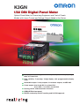
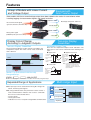
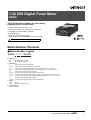
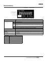
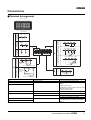
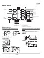
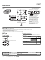
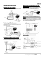
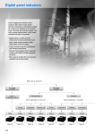
K3GN
1/32 DIN Digital Panel Meter
Optimal Panel Meter for Downsizing Equipment and Control Panels.
Models with Linear Current and Voltage Output Added to the Series.
Additional Models
1/32 DIN Digital Panel Me
ter
• Addition of models with
linear current and voltage
output
• CE marking and UL/CSA
approval
(scheduled to be free of
hazardous
substances by March 2006
)
• Two-color display: gree
n/red
• Multi-range input
● Accepts process voltage/current and pulse input, and displays digital
data, all in one Unit.
● High visibility: 7-mm-high, 5-digit display with programmable display
color.
● Selectable output: 2 relay outputs, 3 transistor outputs, and RS-485.
● Linear output: 0 to 20 mA DC, 4 to 20 mA DC;
0 to 5 VDC, 1 to 5 VDC, 0 to 10 VDC
● Scaling, HOLD, and forced-zero functions.
● NEMA4X/IP66 front panel.
● EN/IEC conformity with CE marking and UL/CSA approval.
Features
Lineup of Models with Linear Current
and Voltage Output
Equipped with
Data Transfer Output
New models with linear current/voltage output have been added to the series for convenience when
handling logging of measurement signals and signal insulation.
Outputs 1 and 2
DC current/current signal
(pressure, distance, flowrate, etc.)
Board-type computers and PLCs
4 to 20 mA DC
Outputs 1 and 2
Rotary pulse signal
(ON/OFF pulse, processor, etc.)
1 to 5 VDC
Display Colors Change
According to Judgment Outputs.
Two-color Display:
Green/Red
Selectable Output Type.
Two-color Display: Green/Red
There are two comparative outputs: OUT1 and OUT2. The
OUT type for each can be selected from the following three
types.
The measurement display section changes according to the
comparative outputs. The status can be easily ascertained
from a distance.
● Upper Limit
Comparative
set value
Red
OUT1
● Upper/Lower Limit
Hysteresis
Measurement
value
ON
Comparative
outputs
OFF
Green
OUT2
Red
Models Can Be Produced with Normally
Energized Relays.
K3GN - 400 24 VDC
Upper-limit set
value for OUT1/2
Measurement
value
Lower-limit set
value for OUT1/2
ON
Comparative
outputs
OFF
Hysteresis
Note: If Upper/Lower Limit is selected, the
upper limit and lower limit for the
comparative set value can be set
individually and will be displayed for
OUT1 and OUT2.
● Lower Limit
Measurement
value
Hysteresis
Comparative
set value
ON
Comparative
outputs
OFF
Note: Refer to page 8 for information on models with normally energized relays.
Multi-range Input
Expanded Range of Applications
● The input type can be selected from among DC voltage, DC
current, and rotary pulse signals.
V
DC voltage input
mA
DC current input
● By using communications, the panel meter can be used as a
serial communications indicator that receives commands
from a PLC or other external device.
• Process meter
• Rotary pulse meter
• Indicator for a PLC or computer using RS485 communications
Hysteresis
Pulse signal input
Digital data
1/32 DIN Digital Panel Meter
K3GN
1/32 DIN Digital Panel Meter for Downsizing
Equipment and Control Panels
• Compact size: 48 x 24 x 83 (W x H x D).
• Multi-input compatible: DC voltage/current, rotary pulse.
• Two display colors (switchable): green/red.
• Selectable outputs.
• CE marking and UL/CSA approval.
• Splash-proof construction (NEMA4X: equivalent to IP66).
Refer to Safety Precautions on page 14.
Model Number Structure
■ Model Number Legend
K3GN-@@-@-@ 24 VDC
1
2
3
4
1. Input Type
ND:
DC voltage/current, NPN
PD:
DC voltage/current, PNP
2. Output Type
C:
2 relay contact outputs (SPST-NO)
C-FLK: 2 relay contact outputs (SPST-NO) and RS-485
C-L1:
2 relay contact outputs (SPST-NO) and DC current (0 to 20 mA, 4 to 20 mA)
C-L2:
2 relay contact outputs (SPST-NO) and DC voltage (0 to 5 V, 1 to 5 V, 0 to 10 V)
T1:
3 transistor outputs (NPN open collector)
T1-FLK: 3 transistor outputs (NPN open collector) and RS-485
T1-L1:
3 transistor outputs (NPN open collector) and DC current (0 to 20 mA, 4 to 20 mA)
T1-L2:
3 transistor outputs (NPN open collector) and DC voltage (0 to 5 V, 1 to 5 V, 0 to 10 V)
T2:
3 transistor outputs (PNP open collector)
T2-FLK: 3 transistor outputs (PNP open collector) and RS-485
3. Option
None:
None
-400:
Normally energized relays
4. Supply Voltage
24 VDC: 24 VDC
1/32 DIN Digital Panel Meter
K3GN
3
Ordering Information
■ List of Models
Supply
voltage
24 VDC
Input type
Output type
Judgement output
DC voltage, DC current,
or NPN input
2 relay contact outputs
(SPST-NO)
2 relay contact outputs
(SPST-NO)
Normally energized
relays (See note.)
Model
Data transmission output
None
K3GN-NDC 24 VDC
RS-485
K3GN-NDC-FLK 24 VDC
DC current (0 to 20 mA, 4 to 20 mA)
K3GN-NDC-L1 24 VDC
DC voltage (0 to 5 V, 1 to 5 V, 0 to 10 V)
K3GN-NDC-L2 24 VDC
None
K3GN-NDC-400 24 VDC
RS-485
K3GN-NDC-FLK-400 24 VDC
DC current (0 to 20 mA, 4 to 20 mA)
K3GN-NDC-L1-400 24 VDC
DC voltage (0 to 5 V, 1 to 5 V, 0 to 10 V)
K3GN-NDC-L2-400 24 VDC
3 transistor outputs (NPN None
open collector)
RS-485
DC voltage, DC current,
or PNP input
2 relay contact outputs
(SPST-NO)
K3GN-NDT1 24 VDC
K3GN-NDT1-FLK 24 VDC
DC current (0 to 20 mA, 4 to 20 mA)
K3GN-NDT1-L1 24 VDC
DC voltage (0 to 5 V, 1 to 5 V, 0 to 10 V)
K3GN-NDT1-L2 24 VDC
None
K3GN-PDC 24 VDC
RS-485
K3GN-PDC-FLK 24 VDC
3 transistor outputs (PNP None
open collector)
RS-485
K3GN-PDT2 24 VDC
K3GN-PDT2-FLK 24 VDC
Note: Refer to page 8 for information on models with normally energized relays.
Specifications
■ Ratings
Item
K3GN-ND
With DC voltage, DC current, and NPN input
Supply voltage
24 VDC
Operating voltage range
85% to 110% of the rated supply voltage
Power consumption (at max. load) (See note 1.)
2.5 W max. (at max. DC load with all indicators lit)
Input signal
K3GN-PD
With DC voltage, DC current, and PNP input
DC voltage, DC current, no-voltage contact, open collector
DC voltage/current
input
A/D conversion
Double integral method
Pulse signal input
Pulse measurement
method
Periodic measurement method
External power supply
None
Control input
Present value hold or forced zero (selectable) (See note 2.)
Outputs
Relay contact output
(Outputs depend on
the model.)
Transistor output
1 A, 30 VDC (resistive load), mechanical life: 50,000,000 operations min., electrical life: 100,000
operations min.
Max. load voltage: 24 VDC, Max. load current: 50 mA, Leakage current: 100 µ A max.
Communications output
RS-485 (2-wire, half-duplex)
Linear output
--DC current (0 to 20 mA DC, 4 to 20 mA: Load:
500 Ω max., Resolution: Approx. 10,000)
DC voltage (0 to 5 VDC, 1 to 5 VDC, 0 to 10 VDC:
Load: 5k Ω min., Resolution: Approx. 10,000)
Display
Negative LCD (backlit LCD) display
7-segment digital display, character height: 7.0 mm, and single illuminated display
Main functions
Scaling, prescaling, teaching, average processing, forced zero, display color selection, output type
selection, key protection, startup compensation timer, hysteresis
Ambient temperature
Operating: −10°C to 55°C (with no condensation or icing)
Storage:
−25°C to 65°C (with no condensation or icing)
Ambient humidity
Operating: 25% to 85%
Altitude
2,000 m max.
Accessories
Rubber packing, fixture, operation manual
Note: 1. A control power supply capacity greater than the rated capacity is required when the Digital Panel Meter is turned ON. Do not forget to
take this into consideration when using several Digital Panel Meters. When power is supplied, all indicators will light and outputs will be
OFF. When using startup compensation time operation, the display will read “00000” and all outputs will be OFF.
2. Enabled only when using DC voltage/current input. (Min.time for control signal input: 80 ms)
4
1/32 DIN Digital Panel Meter K3GN
■ Characteristics
Item
K3GN-ND
With DC voltage, DC current, and NPN input
K3GN-PD
With DC voltage, DC current, and PNP input
Input signal
DC voltage/current (4 to 20 mA, 1 to 5 V, ±5 V, ±10 V)
No-voltage contact (30 Hz max. with ON/OFF pulse width of 16 ms min.)
Open collector (5 kHz max. with ON/OFF pulse width of 90 µs min.)
Displayable range
5 digits (-19999 to 99999)
Sampling period
250 ms
Display refresh period
Sampling period (sampling times multiplied by number of averaging times if average processing is selected.)
Comparative output response
time
(transistor outputs)
750 ms max. (transistor output)
(The time required for the judgment output to be output if the input signal rapidly changes from 15% to 95% or from 95% to 15%.)
Linear output response time
750 ms max. (The time required for the analog output to be
--output if the output signal rapidly changes from 15% to 95% or
from 95% to 15%.)
Insulation resistance
20 MΩ min. (at 500 VDC) between external terminal and case.
Insulation provided between inputs, outputs, and power supply.
Dielectric strength
1,000 VAC for 1 min between external terminal and case.
Noise immunity
±480 V on power supply terminals in normal mode, ±1,500 V in common mode, ±1 µs, or 100 ns for square-wave noise with 1 ns
Vibration resistance
Vibration frequency: 10 to 55 Hz, Acceleration: 50 m/s2 for 10 min each in X, Y, and Z directions
Shock resistance
Models with transistor outputs: 150 m/s2 three times each in 3 axes, 6 directions
Models with contact outputs: 100 m/s2 three times each in 3 axes, 6 directions
Weight
Approx. 100 g (Main Unit only)
Degree of
protection
Front panel
NEMA4X for indoor use (equivalent to IP66),
Rear case
IP20
Terminals
IP00 and finger protection (VDE0106/100)
Memory protection
Non-volatile memory (EEPROM) (possible to rewrite 100,000 times)
Approved standards
UL508, CSA C22.2 No. 142
EMC
(EMI)
Emission Enclosure:
(EMS)
Immunity ESD:
EN 61326
Industry
EN55011 Group 1 class A
EN 61326
Industry
EN 61000-4-2:
4 kV (contact discharge)
8 kV (air discharge)
Immunity RF-interference:
EN 61000-4-3:
10 V/m (amplitude-modulated,
80 MHz to 1 GHz)
Immunity Fast Transient Noise:
EN 61000-4-4:
2 kV (power line)
Immunity Burst Noise:
1 kV line to line (I/O signal line)
Immunity Surge:
EN 61000-4-5:
2 kV line to ground (power line)
Immunity Conducted Disturbance
EN 61000-4-6:
3 V (0.15 to 80 MHz)
Immunity Power Frequency Magnetic EN 61000-4-8:
30 A/m (50 Hz) continuous time
■ Input Ranges: Measurement Range and Accuracy
Input type
Analog
Pulse
Remote
in-t
analg
pulse
rmt
DC
current
input
DC voltage input
Analog
range
4 to 20
mA
Analog
range
range
4-20
range
Connection
terminal
E-F
Connection
terminal
Current range
20.00
(mA)
22.00
Voltage
range (V)10.00
5.000
0.000
4.00
−5.000
0.00
−10.00
Input
impedance
0.00
60 Ω
Input
impedance
Rotary pulse
1 to 5 V
±5 V
±10 V
1-5
5
10
D-E
p-fre
30 Hz
5 kHz
30
5k
B-C
Connection
terminal
11.00
5.500
Pulse
frequency
5.500
Frequency
5000
range
4000
(Hz)
5000
Range of display
from :9999 to
99999 using
communications.
3000
0.000
2000
1000
−5.500
0.0
−11.00
1 MΩ min.
Measurement ±0.1% full scale ± one digit max. (at
accuracy
23±3°C)
±0.1% full scale ± one
digit max. (at 23±5°C)
30.00
0.05
0
---
---
±0.1% full scale ± one digit max. (at
23±5°C)
---
Note: The shaded ranges indicate default settings.
1/32 DIN Digital Panel Meter
K3GN
5
■ Input/Output Ratings
Relay Contact Output
(Incorporating G6K Relays)
Resistive load (cosφ = 1)
Item
Rated load
1 A at 30 VDC
Rated through current
1 A max. (at COM terminal)
Max. contact voltage
60 VDC
Max. contact current
1 A (at COM terminal)
Max. switching capacity
30 VA
Min. permissible load
(P level, reference value)
10 mV, 10 µA
Mechanical life
50,000,000 operations min. (at a
switching frequency of 36,000
operations/hr)
Electrical life
(at an ambient
temperature of 23°C)
100,000 operations min. (at the rated
load with a switching frequency of
1,800 operations/hr)
Transistor Output
Rated load voltage
24 VDC
Max. load current
50 mA
Leakage current
100 µA max.
Communications Specifications
Item
RS-485
Communications method 2-wire, half-duplex
Synchronization method Start-stop synchronization
Baud rate
1,200/2,400/4,800/9,600/19,200 bps
Transmission code
ASCII
Commu- Reading/
nications Writing to the
K3GN
Read/write comparative set values,
read/write scaling values, enable/
disable the writing of data through
communications, forced-zero control,
and other data.
Linear Output
Item
0 to
20 mA
4 to 0 to 5 V 1 to 5 V
20 mA
Permissible load
impedance
500 Ω max.
Resolution
Approx. 10,000
Output error
±0.5% full scale
6
0 to
10 V
5 kΩ min.
±0.5 full scale.
±0.15 V at 1 V or less (no
output for 0 or less)
1/32 DIN Digital Panel Meter K3GN
Nomenclature
1. Main display
2. Status indicators
2. Status indicators
3. Level indicator
4. Level key
5. Mode key
Name
6. Shift key
7. Up/Zero key
Functions
1. Main display
Displays process values, parameters, and set values.
2. Status indicators
OUT1
Lit when output 1 is ON.
OUT2
Lit when output 2 is ON.
SV
Lit when a set value is being displayed or changed.
T
Lit when the teaching function is enabled. Flashes when the K3GN is in teaching operation.
Lit when a calibration value is being displayed during user calibration. Flashes while reading a calibration value.
ZERO
Lit while the forced-zero function is activated.
HOLD
Lit when HOLD input is ON.
CMW
Lit when communications writing is “enabled” and is out when it is “disabled.”
3. Level indicator
Displays the current level that the K3GN is in. (See below for details.)
4. Level Key
Used to change the level.
5. Mode Key
Used to allow the Main display to indicate parameters sequentially.
6. Shift Key
Used to enable that set value to be changed. When changing a set value, this key is used to move
along the digits.
7. Up/Zero Key
Used to change a set value. Used to set or clear a forced-zero function when a measurement value is
being displayed.
Level indicator
p
Not lit
a
s
c
f
u
Level
Protect
Operation
Adjustment
Initial setting
Communications setting
Advanced function setting
User calibration
1/32 DIN Digital Panel Meter
K3GN
7
Models with Normally Energized Relays
K3GN-NDC-@-400 24 VDC
Relation between Output Type and Relay
• The drive operation for the output relay is reversed in these models.
• Relay contacts can be made open (i.e., OFF) when comparative set
values are being judged. This is effective when constructing systems
that take failsafe measures into consideration.
List of Models
Models with Normally Energized Relays
K3GN-NDC-400 24 VDC
Output Operation
Upper limit
Set value
Upper and lower limits
Hysteresis
Measurement
value
ON
Output
OFF
Lower limit
K3GN-NDC-FLK-400 24 VDC
K3GN-NDC-L1-400 24 VDC
K3GN-NDC-L2-400 24 VDC
Measurement
value
Set value
ON
Output
OFF
8
1/32 DIN Digital Panel Meter K3GN
Hysteresis
Upper-limit
set value
Measurement
value
Lower-limit
set value
ON
Output
OFF
Note:
Hysteresis
Hysteresis
If Upper/Lower Limit is selected, the
upper limit and lower limit for the comparative set value can be set individually and will be displayed for OUT1 and
OUT2.
Connections
■ Terminal Arrangement
Output terminals
7
8
Models with
relay outputs
NC
RS-485
8
7
B (+)
A (−)
C
7
8
(+)
(−)
1
D
7
8
1
2
9 10 11 12
3
4
5
6
A
2
D
B
3
Operation
power supply
24 VDC
OUT1
9
Models with
Models with
PNP transistor outputs NPN transistor outputs
NC
NC OUT2
COM
10 11 12
OUT1 PASS OUT2 COM
9
10 11 12
OUT1 PASS OUT2
9
10 11
5
6
COM
12
Event or pulse/contact input
1
Operation
power supply
24 VDC
2
3
B
Analog input
A
Models with PNP inputs Models with NPN inputs
Models with
linear output
C
Models with
communications
Models without
communications
Input terminals
4
COM
Voltage Current
Analog input
Event or pulse/contact input
Terminal No.
Name
Description
A-B
Operation power
Connect the operation power supply.
C-B
Event input or pulse/contact input
Operates as follows depending on parameter
setting:
• Holds process value.
• Calibrate the process value to zero and clear
the forced-zero function.
• Pulse or contact input.
C-A
D,F-E
Analog input
Connect the voltage or current analog input.
G-H
Communications
RS-485 communications terminals.
Linear output
0 to 20 mA DC, 4 to 20 mA DC
0 to 5 VDC, 1 to 5 VDC, 0 to 10 VDC
I,K-L
I,J,K-L
Outputs
Outputs relay or transistor outputs. There is
also a PASS output for models with transistor
outputs.
1/32 DIN Digital Panel Meter
K3GN
9
■ Block Diagram
Key
Analog input
terminal
Display
Transistor output
(See note 1.)
A/D
conversion
circuit
Input circuit
Drive circuit
Output
circuit
Drive circuit
Microcomputer
EEPROM
Output
circuit
Drive circuit
Pulse/
Control
input
terminal
Contact output
(See note 3.)
X
Communications terminal
(See note 4.)
Communications driver
Drive circuit
Waveform
rectification
circuit
Control input
circuit
Linear output
(See note 2.)
Constant voltage circuit 1
Constant voltage circuit 2
Power supply circuit
Note: 1.
2.
3.
4.
Operating power supply
Transistor output models only.
Linear output models only.
Relay output models only.
Models with communications functions only.
■ Input Circuits
Analog Input (DC Voltage/Current)
Pulse Input/Control Event Input (HOLD/
ZERO)
Use terminal 5 for analog common.
−
Voltage 4
input
−
To A/D
Current 6
input
+
COM 5
To A/D
+
• Use terminal 2 for the common terminal.
• Use the NPN open collector or the no-voltage contacts for the
control input.
NPN Input
24 VDC
COM 5
1
Comparative Output
2
Contact Output
3
24 V
2.35 kΩ
5V
4.7 kΩ
PNP Input
X
OUT1
OUT2
24 VDC +
1
2.35 kΩ
3
Hold/Zero Pulse
4.7 kΩ
Transistor Output
24 VDC −
PNP Output
NPN Output
8.2 Ω
8.2 Ω
8.2 Ω
9 OUT1
10 PASS
11 OUT2
12 COM
10
12 COM
8.2 Ω
11 OUT2
8.2 Ω
10 PASS
8.2 Ω
1/32 DIN Digital Panel Meter K3GN
9
OUT1
2
Linear Output
Linear voltage output
+
5 kΩ
L
min.
−
Linear current output
−
−
7
+
500 Ω
L
max.
+
8
−
+
7
Note: The commons for linear output and transistor output on models
with L1 and L2 are connected internally.
Depending on how the common is wired for externally
connected devices, unwanted current paths for the linear
output signal in the circuit may prevent the output signal from
being output.
When connecting an external device, externally connect a relay
to the transistor output or provide another means of insulation.
8
Operation
■ Main Functions
Changing the Display Color
The K3GN includes a scaling function that can convert the input
signal to a desired value and display that value.
The color of the value displayed can be set to either red or green.
Make the setting according to the purpose and application of the
equipment in which the K3GN is installed. The display color can also
be set to change from green to red, or from red to green, according
to the status of the comparison criteria.
The displayed values can be freely adjusted to shift values, to create
reversed displays, or to create positive/negative displays.
Output Type Selection
Scaling
Display
value
DISPLAY2
Display
value
DISPLAY2
DISPLAY1
DISPLAY1
(
INPUT1 INPUT2
) (
) Input value
Output operation for comparative set values can be freely selected.
Upper limit: Output ON if the measurement value ≥ comparative set
value.
Lower limit: Output ON if the measurement value ≤ comparative set
value.
Upper/lower limit: Output ON if the measurement value ≥
comparative upper-limit set value or if the measurement value is ≤
the comparative lower-limit value.
INPUT1
INPUT2
Input
value
Teaching
Teaching is used when using scaling or setting comparative set
values to set the present measurement values as the set values
instead of inputting with the Shift and Up/Zero Keys. Teaching is
useful for making settings while checking the operation status of the
K3GN.
Average Processing
Average processing can be performed for measurement values using
four levels (OFF, 2 times, 4 times, or 8 times). Average processing
stabilizes displayed values by averaging the corresponding input
signals that fluctuate dynamically. Select the appropriate number of
averaging times depending on the application.
Key protection is used to restrict changes to displays and settings
using the front panel keys and to restrict menu display and
movement of operation levels. This function is effective for preventing
misuse during operation.
Startup Compensation Time (Rotary
Pulse Input Only)
The startup compensation time parameter keeps the measurement
operation from sending an unnecessary output corresponding to
instantaneous, fluctuating input from the moment the K3GN is turned
ON until the end of the preset period.
Hysteresis
The hysteresis of comparative outputs can be set to prevent the chattering of relay or transistor outputs.
Forced-zero Function
It is possible to shift from a
value to the zero point with
one touch of the Up/Zero
Key on the front panel (for
example, when adjusting
reference values).
Key Protection
K3GN
OUT1
ZERO
OUT2
HOLD
SV
CMW
/ZERO
Note: This function can be
used only when
forced-zero operation
protection is released.
1/32 DIN Digital Panel Meter
K3GN
11
Dimensions
Note: All units are in millimeters unless otherwise indicated.
K3GN
Panel Cutout Dimensions
Separate mounting
44.8
Gang mounting
(48 × No. of Panels − 2.5) +1.0
0
+0.6
45 0
+0.3
22.2
22.2 0
+0.3
0
40 min.
The products cannot be
made waterproof when
gang-mounted.
K3GN
OUT1
35 24
ZERO
T
HOLD
OUT2
22
CMW
SV
/ZERO
48
80
3
The K3GN uses M3 terminals. A terminal
cover is provided.
Main Display Character Size
7 mm
• For installation, insert the K3GN
panel into the rectangular hole,
insert the adaptor from the rear, and
push it in to reduce the gap between
the panel surface and the adaptor.
Secure the Unit with the screws.
For water-proof installation, insert
the rubber gasket onto the body of
the K3GN.
• If multiple mounted Units are used,
make sure the ambient temperature
for the K3GN does not exceed the
specified temperature.
3.6 mm
■ Wiring Precautions
•
•
•
•
Wire the power supply with the correct polarity. Wiring with incorrect polarity may result in damage or burning.
Wire the terminals using crimp terminals.
Tighten terminal screws to a torque of approx. 0.5 N·m.
Wire signal lines and power lines separately to reduce the influence of noise.
■ Wiring
Measurement Input
Power Supply
The following table shows the relation between input ranges and
input terminals.
• Input 24 VDC to terminals 1 and 2.
1
24 VDC
2
• Use M3 crimp terminals of the type shown below.
5.8 mm max.
Input range
DC voltage/DC current
Input
terminals
4 to 20 mA
E-F
1 to 5 V
D-E
±5 V
±10 V
No-voltage contacts and NPN open collector
(Models with NPN inputs)
B-C
No-voltage contacts and PNP open collector
(Models with PNP inputs)
A-C
5.8 mm max.
Be sure to read the Precautions for Correct Use and other information required when using the K3GN in the
following user’s manual.
K3GN Digital Panel Meter User’s Manual (Cat.No. N102)
12
1/32 DIN Digital Panel Meter K3GN
■ Application Examples
Monitoring Difference between Two
Line Speeds
Detection of Dust Exhaust
The change in the density of the dust is detected via the E3SA and
discriminated by the K3GN.
The difference between the two line speeds is calculated by the PLC
and the result is written via RS-485 to the K3GN where it is
displayed.
RS-485 communications output
(calculation result)
Exhaust
4 to 20 mA
Grinder
K3GN
(Set the input type to
"Remote").
K3GN
E3SA
Monitoring the Remaining Quantity of
Soup
Dust collecting machine
OUT2
(Upper upperlimit alarm)
Device stops
OUT1
(Upper-limit
alarm) Output
reduction
instruction
The distance to the surface of the soup is detected with an ultrasonic
sensor and, based on this distance, the K3GN displays the remaining
quantity. When the remaining quantity of soup decreases to less than
20%, the K3GN lights the “Replenish” indicator.
Monitoring of Tank Pressure
The output of the pressure sensor is processed and the pressure is
displayed. Remote monitoring of the operation is possible with the
communications function.
4 to 20 mA
Ultrasonic Sensor
100 %
K3GN
Volume of soup
OUT 1
Replenish
Large
cup
Medium
cup
20 %
E8AA
Pressure
Sensor
Small
cup
K3GN
Host PC
RS-485
Foam
RS-232C
Beer
Monitoring Number of Motor
Revolutions
Pump
Tank
Exhaust valve
Monitoring of Motor Load Current
If the startup time compensation of the K3GN is enabled, the K3GN
will not be influenced by the inrush current from starting the motor,
and no signal will be output from the K3GN.
Power supply
Electromagnetic relay
Power supply
Signal input
24-VDC power supply
Electromagnetic relay
4 to 20 mA
OUT1 (Upper limit)
24-VDC power supply
0 to 1 A
Signal input
K3FK CT Converter
OUT2 (Lower limit)
K3GN-NDC
OUT1 (Upper limit)
OUT1
(Upper-limit
alarm)
K3GN
E2E Proximity
Sensor
OUT2 (Lower limit)
K3GN-NDC
OUT2
(Lower-limit
alarm)
K3FK
CT Converter
1/32 DIN Digital Panel Meter
K3GN
13
Safety Precautions
!CAUTION
Do not touch the terminals while power is being supplied.
Doing so may possibly result in electric shock.
Do not allow pieces of metal, wire clippings, or fine
metallic shavings or filings to enter the product. Doing so
may occasionally result in minor or moderate injury or in
property damage due to electric shock, fire, or
malfunction caused by internal short circuiting.
Do not use the product in locations where flammable or
explosive gases are present. Doing so may occasionally
result in minor or moderate explosion, causing minor or
moderate injury, or property damage.
Do not use the equipment for measurements within
Measurement Categories II, III, or IV (according to IEC
61010-1). Doing so may occasionally cause unexpected
operation, resulting in minor or moderate injury, or
damage to the equipment. Use the equipment for
measurements only within the Measurement Category for
which the product is designed.
Failure to perform correct setting of the product according
to the application may occasionally cause unexpected
operation, resulting in minor or moderate injury, or
damage to the equipment. Ensure safety in the event of
product failure by taking safety measures, such as
installing a separate monitoring system.
Product failure may occasionally prevent operation of
comparative outputs, resulting in damage to the
connected facilities and equipment. Ensure safety in the
event of product failure by taking safety measures, such
as installing a separate monitoring system.
Tighten the screws on the terminal block and the
connector locking screws securely using a tightening
torque within the following ranges. Loose screws may
occasionally cause fire, resulting in minor or moderate
injury, or damage to the equipment.
Terminal block screws: 0.43 to 0.58 N·m
Do not attempt to disassemble, repair, or modify the
product. Doing so may occasionally result in minor or
moderate injury due to electric shock.
■ Precautions for Safe Use
Environmental Precautions
1. Do not use the product in the following locations.
• Locations subject to direct radiant heat from heating equipment
• Locations where the product may come into contact with water or
oil
• Locations subject to direct sunlight
• Locations where dust or corrosive gases (in particular, sulfuric or
ammonia gas) are present
• Locations subject to extreme temperature changes
• Locations where icing or condensation may occur
• Locations subject to excessive shocks or vibration
2. Do not use the product in locations subject to temperatures or
humidity levels outside the specified ranges or in locations prone
to condensation. If the product is installed in a panel, ensure that
the temperature around the product (not the temperature around
the panel) does not go outside the specified range. Parts life is
dependent on temperatures. A part life shortens when the
temperature rises, and it lengthens when the temperature falls.
Parts life can be lengthened by lowering the temperature inside
the product.
3. In order to prevent inductive noise, wire the lines connected to the
product separately from power lines carrying high voltages or
currents. Do not wire in parallel with or in the same cable as
power lines. Other measures for reducing noise include running
lines along separate ducts and using shield lines.
4. Do not install the product near devices generating strong highfrequency waves or surges. When using a noise filter, check the
voltage and current and install it as close to the product as
possible. If several products are mounted side-by-side or
arranged in a vertical line, the heat dissipation will cause the
internal temperature of the product to rise, shortening the service
life. If necessary, cool the products using a fan or other cooling
method.
5. Take care when cleaning the product, because the exterior of the
product may be damaged by organic solvents (thinner, benzine,
etc.), strong alkaline materials and strong acid materials.
6. Avoid storing in high humidity or in a corrosive gas environment
(including during transportation)
Precautions for Safe Use
1. Use and store within the proper temperature and humidity
described in the specifications.
2. Provide sufficient space around the product for heat dissipation.
3. When using the product stored unused over a year after
purchasing, the product features may not be utilized sufficiently.
4. Avoid storing outdoors or in a place that receives direct sunlight
(including during transportation).
5. The service life of the output relays depends on the switching
capacity and switching conditions. Consider the actual application
conditions and use the product within the rated load and electrical
service life. Using the product beyond its service life may result in
contact welding or burning.
6. Be sure to confirm the name and polarity for each terminal before
wiring the terminal block and connectors. Faulty wiring may cause
destruction or burnout of internal parts.
7. Use the product within the noted supply voltage and rated load.
8. Do not connect anything to unused terminals.
9. Output turns OFF when the mode is changed or settings are
initialized. Take this into consideration when setting up the control
system.
10.Install an external switch or circuit breaker and label them clearly
so that the operator can quickly turn OFF the power.
14
1/32 DIN Digital Panel Meter K3GN
11.Ensure that the rated voltage is achieved no longer than 2 s after
turning the power ON. When applying a voltage gradually, the
power supply may not reset or the output may function in an
uncertain manner.
12.Mount to a panel between 1 and 5 mm thick.
13.Use the specified size of crimp terminals (M3, width: 5.8 mm
max.) for wiring. To connect bare wires, use AWG 28 to AWG 16
to wire the power supply terminals and AWG 22 to AWG 14 for
other terminals. (Length of exposed wire: 6 to 8 mm)
14.Allow the product to operate without load for at least 15 minutes
after the power is turned ON.
■ Precautions for Correct Use
1. Note that errors may be increased by the magnification of the
scaling function.
2. When using a noise filter on the power supply, check that the filter
is suitable for the supply voltage and current ratings, and then
attach the noise filter as close as possible to the K3GN.
Line filter
24 VDC
Power
supply
input
Digital
Panel Meter
Shielded cable
Signal
inputs
Digital
Panel Meter
Connect in the direction that best
reduces noise.
3. Avoid using the K3GN in places near a radio, television, or other
wireless device. These devices can cause radio disturbances
which will adversely affect the K3GN.
1/32 DIN Digital Panel Meter
K3GN
15
Warranty and Application Considerations
Read and Understand This Catalog
Please read and understand this catalog before purchasing the products. Please consult your OMRON representative if you
have any questions or comments.
Warranty and Limitations of Liability
WARRANTY
OMRON's exclusive warranty is that the products are free from defects in materials and workmanship for a period of one year (or
other period if specified) from date of sale by OMRON.
OMRON MAKES NO WARRANTY OR REPRESENTATION, EXPRESS OR IMPLIED, REGARDING NON-INFRINGEMENT,
MERCHANTABILITY, OR FITNESS FOR PARTICULAR PURPOSE OF THE PRODUCTS. ANY BUYER OR USER
ACKNOWLEDGES THAT THE BUYER OR USER ALONE HAS DETERMINED THAT THE PRODUCTS WILL SUITABLY MEET
THE REQUIREMENTS OF THEIR INTENDED USE. OMRON DISCLAIMS ALL OTHER WARRANTIES, EXPRESS OR
IMPLIED.
LIMITATIONS OF LIABILITY
OMRON SHALL NOT BE RESPONSIBLE FOR SPECIAL, INDIRECT, OR CONSEQUENTIAL DAMAGES, LOSS OF PROFITS,
OR COMMERCIAL LOSS IN ANY WAY CONNECTED WITH THE PRODUCTS, WHETHER SUCH CLAIM IS BASED ON
CONTRACT, WARRANTY, NEGLIGENCE, OR STRICT LIABILITY.
In no event shall the responsibility of OMRON for any act exceed the individual price of the product on which liability is asserted.
IN NO EVENT SHALL OMRON BE RESPONSIBLE FOR WARRANTY, REPAIR, OR OTHER CLAIMS REGARDING THE
PRODUCTS UNLESS OMRON'S ANALYSIS CONFIRMS THAT THE PRODUCTS WERE PROPERLY HANDLED, STORED,
INSTALLED, AND MAINTAINED AND NOT SUBJECT TO CONTAMINATION, ABUSE, MISUSE, OR INAPPROPRIATE
MODIFICATION OR REPAIR.
Application Considerations
SUITABILITY FOR USE
OMRON shall not be responsible for conformity with any standards, codes, or regulations that apply to the combination of
products in the customer's application or use of the products.
Take all necessary steps to determine the suitability of the product for the systems, machines, and equipment with which it will
be used.
Know and observe all prohibitions of use applicable to this product.
NEVER USE THE PRODUCTS FOR AN APPLICATION INVOLVING SERIOUS RISK TO LIFE OR PROPERTY WITHOUT
ENSURING THAT THE SYSTEM AS A WHOLE HAS BEEN DESIGNED TO ADDRESS THE RISKS, AND THAT THE OMRON
PRODUCTS ARE PROPERLY RATED AND INSTALLED FOR THE INTENDED USE WITHIN THE OVERALL EQUIPMENT OR
SYSTEM.
Disclaimers
PERFORMANCE DATA
Performance data given in this catalog is provided as a guide for the user in determining suitability and does not constitute a
warranty. It may represent the result of OMRON's test conditions, and the users must correlate it to actual application
requirements. Actual performance is subject to the OMRON Warranty and Limitations of Liability.
CHANGE IN SPECIFICATIONS
Product specifications and accessories may be changed at any time based on improvements and other reasons. Consult with
your OMRON representative at any time to confirm actual specifications of purchased product.
DIMENSIONS AND WEIGHTS
Dimensions and weights are nominal and are not to be used for manufacturing purposes, even when tolerances are shown.
ALL DIMENSIONS SHOWN ARE IN MILLIMETERS.
To convert millimeters into inches, multiply by 0.03937. To convert grams into ounces, multiply by 0.03527.
Cat. No. N160-E1-01
In the interest of product improvement, specifications are subject to change without notice.
OMRON Corporation
Regional Headquarters
Industrial Automation Company
OMRON EUROPE B.V.
Wegalaan 67-69, NL-2132 JD Hoofddorp
The Netherlands
Tel: (31)2356-81-300/Fax: (31)2356-81-388
Control Devices Division H.Q.
Analog Controller Division
Shiokoji Horikawa, Shimogyo-ku,
Kyoto, 600-8530 Japan
Tel: (81)75-344-7080/
Fax: (81)75-344-7189
OMRON ELECTRONICS LLC
1 East Commerce Drive, Schaumburg,
IL 60173 U.S.A.
Tel: (1)847-843-7900/Fax: (1)847-843-8568
OMRON ASIA PACIFIC PTE. LTD.
83 Clemenceau Avenue,
#11-01, UE Square,
239920 Singapore
Tel: (65)6835-3011/Fax: (65)6835-2711
OMRON (CHINA) CO., LTD.
Room 2211, Bank of China Tower,
200 Yin Cheng Road (M),
Shanghai, 200120 China
Tel: (86)21-5037-2222/Fax: (86)21-5037-2200
1205-1.5M (1205) (D)


![[DRAFT] DEMO908JL16 User`s Manual](http://vs1.manualzilla.com/store/data/005639706_1-2a84cd2ce2f0b318fdb7aae7896f2a79-150x150.png)