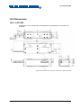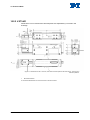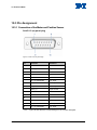
1
MP124E V-273 VC Linear Actuator User Manual Version: 1.0.0 Date: 30.03.2015 This document describes the following products: V-273.430 PIMag® Voice Coil Linear Actuator, 20 mm, 6 N, Linear Encoder, 0.1 µm Resolution V-273.431 PIMag® Voice Coil Linear Actuator, 20 mm, 6 N, Linear Encoder, 0.1 µm Resolution, Force Sensor Physik Instrumente (PI) GmbH & Co. KG, Auf der Roemerstr. 1, 76228 Karlsruhe, Germany Phone: +49 721 4846-0, Fax: +49 721 4846-1019, E-mail: [email protected] Physik Instrumente (PI) GmbH & Co. KG is the owner of the following trademarks: PI®, PIC®, PICMA®, PILine®, PIFOC®, PiezoWalk®, NEXACT®, NEXLINE®, NanoCube®, NanoAutomation®, Picoactuator®, PInano®, PIMag® PI owns the following patents or patent applications for the technology field Magnetic Direct Drives (PIMag®): WO212146709A2, DE102012207082A1 © 2015 Physik Instrumente (PI) GmbH & Co. KG, Karlsruhe, Germany. The text, photographs and drawings in this manual are protected by copyright. With regard thereto, Physik Instrumente (PI) GmbH & Co. KG retains all the rights. Use of said text, photographs and drawings is permitted only in part and only upon citation of the source. Original instructions First printing: 30.03.2015 Document number: MP124E, KSch, Version 1.0.0 Subject to change without notice. This manual is superseded by any new release. The latest release is available for download (p. 3) on our website. Contents 1 About this Document 1.1 1.2 1.3 1.4 1.5 1.6 2 3 Goal and Target Audience of this User Manual ...................................................1 Symbols and Typographic Conventions ...............................................................1 Definition ...............................................................................................................2 Figures ..................................................................................................................3 Other Applicable Documents ................................................................................3 Downloading Manuals ..........................................................................................3 Safety 2.1 2.2 2.3 5 Intended Use ........................................................................................................5 General Safety Instructions ..................................................................................5 Organizational Measures ......................................................................................6 Product Description 3.1 3.2 3.3 3.4 3.5 1 7 Model Overview ....................................................................................................7 Product View.........................................................................................................7 3.2.1 Overview .............................................................................................7 3.2.2 Product Details ...................................................................................8 3.2.3 Product Labeling .................................................................................9 Scope of Delivery ...............................................................................................10 Suitable Controllers ............................................................................................11 Technical Features .............................................................................................11 3.5.1 Linear Encoder .................................................................................11 3.5.2 Reference Point Switch ....................................................................11 3.5.3 Force Sensor ....................................................................................12 3.5.4 ID Chip ..............................................................................................12 4 Unpacking 13 5 Installation 15 5.1 5.2 5.3 5.4 6 Start-Up and Operation 6.1 6.2 7 General Notes on Installation .............................................................................15 Optional: Changing the Contact Piece of the Force Sensor on the V273.431 Model: ...................................................................................................16 Installing the V-273 in a Mechanical Mounting ...................................................17 Connecting the Motor Cable to the V-273 ..........................................................20 General Notes on Start-Up and Operation .........................................................21 Starting Up the V-273 with the C-413 Controller ................................................24 Maintenance 7.1 7.2 21 27 General Notes on Maintenance ..........................................................................27 Cleaning the V-273 .............................................................................................27 8 Troubleshooting 29 9 Customer Service 31 10 Technical Data 33 10.1 10.2 10.3 Specifications......................................................................................................33 10.1.1 Data Table ........................................................................................33 10.1.2 Maximum Ratings .............................................................................35 10.1.3 Ambient Conditions and Classifications ...........................................35 10.1.4 Reference Point Switch Specifications .............................................36 Dimensions .........................................................................................................37 10.2.1 V-273.430 .........................................................................................37 10.2.2 V-273.431 .........................................................................................38 Pin Assignment ...................................................................................................40 10.3.1 Connection of the Motor and Position Sensor ..................................40 10.3.2 V-273.431: Connection of the Force Sensor ....................................41 11 Old Equipment Disposal 43 12 EC Declaration of Conformity 45 1 About this Document 1 About this Document In this Chapter Goal and Target Audience of this User Manual ............................................................ 1 Symbols and Typographic Conventions ........................................................................ 1 Definition ........................................................................................................................ 2 Figures ........................................................................................................................... 3 Other Applicable Documents ......................................................................................... 3 Downloading Manuals ................................................................................................... 3 1.1 Goal and Target Audience of this User Manual This manual contains information on the intended use of the V-273. It assumes that the reader has a fundamental understanding of basic servo systems as well as motion control concepts and applicable safety procedures. The latest versions of the user manuals are available for download (p. 3) on our website. 1.2 Symbols and Typographic Conventions The following symbols and typographic conventions are used in this user manual: NOTICE Dangerous situation If not avoided, the dangerous situation will result in damage to the equipment. Actions to take to avoid the situation. INFORMATION Information for easier handling, tricks, tips, etc. V-273 VC Linear Actuator MP124E Version: 1.0.0 1 1 About this Document Symbol/Label Meaning 1. Action consisting of several steps whose sequential order must be observed 2. Action consisting of one or several steps whose sequential order is irrelevant List item p. 5 Cross-reference to page 5 RS-232 Labeling of an operating element on the product (example: socket of the RS-232 interface) Warning sign on the product which refers to detailed information in this manual. 1.3 Definition Term Explanation VC linear actuator / VC = Voice Coil VC linear drive The feed is generated by the Lorentz force on an energized coil (PIMag® principle) that couples to a moving rod. The V-273 thus combines a relatively long travel range with a high velocity and a high resolution. Max. push/pull force Maximum force in the direction of motion. Position or velocity control: When a counterforce is exerted on the linear actuator, the linear actuator counteracts it with maximum force to maintain the target position or target velocity. When the counterforce exceeds the specified value of the push/pull force (p. 33), displacements or changes in velocity can occur. Force control: When a counterforce is exerted on the linear actuator, the linear actuator maximally counteracts it with the target force value. If the counterforce exceeds the target force value, displacements are possible. When the servo mode is switched off, the weight force of the moving mass can be compensated for by an AutoZero procedure (see user manual of the C-413 controller). 2 Version: 1.0.0 MP124E V-273 VC Linear Actuator 1 About this Document Term Explanation Incremental position Sensor (encoder) for capturing changes of position or changes sensor of angle. Signals from the incremental position sensor are used for axis position feedback. After switching on the controller a reference point definition must be performed before absolute target positions can be commanded and reached. 1.4 Figures For better understandability, the colors, proportions and degree of detail in illustrations can deviate from the actual circumstances. Photographic illustrations may also differ and must not be seen as guaranteed properties. 1.5 Other Applicable Documents The devices and software tools which are mentioned in this documentation are described in their own manuals. Product Document C-413 PIMag® Controller MS224E User Manual PIMikroMove SM148E Software Manual 1.6 Downloading Manuals INFORMATION If a manual is missing or problems occur with downloading: Contact our customer service department (p. 31). V-273 VC Linear Actuator MP124E Version: 1.0.0 3 1 About this Document INFORMATION For some products (e.g. Hexapod systems and electronics that are delivered with a CD), access to the manuals is password-protected. The password is stored on the CD. Availability of the manuals: Password-protected manuals: FTP download directory Follow the corresponding instructions for downloading. Freely available manuals: PI website Download freely accessible manuals 1. Open the website http://www.pi-portal.ws. 2. Click Downloads. 3. Click the corresponding product category. 4. Go to the corresponding product code. The available manuals are displayed. 5. Click the desired manual and save it on the hard disk of your PC or on a data storage medium. Download password-protected manuals 1. Insert the product CD in the PC drive. 2. Switch to the Manuals directory on the CD. 3. In the Manuals directory, open the Release News (file including releasenews in the file name). 4. Find the user name and the password in the section "User login for software download" in the Release News. 5. Open the FTP download directory (ftp://pi-ftp.ws). − Windows operating systems: Open the FTP download directory in Windows Explorer. 6. Log in with the user name and the password from the Release News. 7. In the directory of the corresponding product, go to the Manuals sub-directory. 8. Copy the desired manual to the hard disk of your PC or to a data storage medium. 4 Version: 1.0.0 MP124E V-273 VC Linear Actuator 2 Safety 2 Safety In this Chapter Intended Use ................................................................................................................. 5 General Safety Instructions ........................................................................................... 5 Organizational Measures............................................................................................... 6 2.1 Intended Use The V-273 is a laboratory device as defined by DIN EN 61010-1. It is intended to be used in interior spaces and in an environment which is free of dirt, oil, and lubricants. The V-273 has a VC linear drive (p. 2), a position sensor and, depending on the model, a force sensor as well. The V-273 is intended for positioning, adjusting and shifting loads in one axis at various velocities and with defined forces. The V-273 is a linear actuator for applications in automation or handling technology. The V-273 is not intended for applications in areas in which a failure would present severe risks to human beings or the environment. The intended use of the V-273 is only possible when installed and in connection with a suitable controller (p. 11). The controller is not included in the scope of delivery of the V-273. 2.2 General Safety Instructions The V-273 is built according to state-of-the-art technology and recognized safety standards. Improper use can result in personal injury and/or damage to the V-273. Only use the V-273 for its intended purpose, and only use it if it is in a good working order. Read the user manual. Immediately eliminate any faults and malfunctions that are likely to affect safety. The operator is responsible for the correct installation and operation of the V-273. V-273 VC Linear Actuator MP124E Version: 1.0.0 5 2 Safety 2.3 Organizational Measures User manual Always keep this user manual available by the V-273. The latest versions of the user manuals are available for download (p. 3) on our website. Add all information given by the manufacturer to the user manual, for example supplements or Technical Notes. If you pass the V-273 on to other users, also turn over this user manual as well as other relevant information provided by the manufacturer. Only use the device on the basis of the complete user manual. If your user manual is incomplete and is therefore missing important information, property damage can result. Only install and operate the V-273 after having read and understood this user manual. Personnel qualification The V-273 may only be installed, started up, operated, maintained and cleaned by authorized and appropriately qualified personnel. 6 Version: 1.0.0 MP124E V-273 VC Linear Actuator 3 Product Description 3 Product Description In this Chapter Model Overview ............................................................................................................. 7 Product View ................................................................................................................. 7 Scope of Delivery ........................................................................................................ 10 Suitable Controllers ..................................................................................................... 11 Technical Features ...................................................................................................... 11 3.1 Model Overview Two standard versions of the V-273 linear actuator are available. They differ with regard to the force sensor and thus the dimensions. Model Dimension Force sensor present? V-273.430 200 mm x 51 mm x 37.2 mm No V-273.431 205.5 mm x 51 mm x 37.2 mm Yes For further technical data, see the specifications (p. 33). 3.2 Product View 3.2.1 Overview Figure 1: V-273.430 (left) and V-273.431 (right) V-273 VC Linear Actuator MP124E Version: 1.0.0 7 3 Product Description 3.2.2 Product Details Figure 2: Front side of the V-273.430 linear actuator 1 Moving rod (= guide rail) 2 Case 3 Connection for motor cable (panel plug, Sub-D 15) x Positive direction of motion Figure 3: Front side of the V-273.431 linear actuator 8 1 Cable exit of the force sensor 2 Exchangeable contact piece of the force sensor 3 Force sensor 4 Moving rod (= guide rail) 5 Case 6 Connection for motor cable (panel plug, Sub-D 15) x Positive direction of motion Version: 1.0.0 MP124E V-273 VC Linear Actuator 3 Product Description Figure 4: Force sensor of the V-273.431 model 1 M3 threaded bolt for screwing the contact piece onto the force sensor Figure 5: Rear side of the V-273 linear actuator, hole pattern and transport lock are identical for both standard versions 1 Case 2 Transport lock (M2.5 screw) 3.2.3 Product Labeling On the case of the V-273, there is a type plate with the following information: Labeling Description Data matrix code (example; contains the serial number) V-273.430 V-273 VC Linear Actuator Product name (example), the places after the point refer to the model MP124E Version: 1.0.0 9 3 Product Description Labeling Description 114003601 Serial number (example), individual for each V273 Meaning of the places (counting from left): 1 = internal information, 2 and 3 = manufacturing year, 4 to 9 = consecutive numbers Manufacturer's logo Warning sign "Observe manual!" Old equipment disposal (p. 43) Country of origin: Germany Country of origin WWW.PI.WS Manufacturer's address (website) CE conformity mark 3.3 Scope of Delivery Item ID Component V-273.430 Linear actuator according to order (p. 7) or V-273.431 10 000025499 M2.5x12 A2 screw ISO 14580 as transport lock C-815.18 Sub-D 15 (m/f) motor cable, 1 m MP124E User manual (this document) in printed form Version: 1.0.0 MP124E V-273 VC Linear Actuator 3 Product Description 3.4 Suitable Controllers The V-273 must be connected to a suitable controller. The following controllers from PI are suitable for the operation of the V-273: Controller Description C-413.20 PIMag® Motion Controller, 2 Channels, USB Interface, OEM Board, Force Control Option C-413.20A PIMag® Motion Controller, 2 Channels, USB Interface, Analog Inputs, OEM Board, Force Control Option C-413.2G PIMag® Motion Controller, 2 Channels, USB Interface, Bench-Top Device, Force Control Option C-413.2GA PIMag® Motion Controller, 2 Channels, USB Interface, Analog Inputs, Bench-Top Device, Force Control Option PC software is included in the scope of delivery of the controllers from PI. The operation of the controllers is described in the corresponding user manuals. 3.5 Technical Features 3.5.1 Linear Encoder The V-273 is equipped with an optical linear encoder. For the resolution, refer to the table in the "Specifications" section (p. 33). Optical linear encoders measure the actual position directly (direct metrology). Therefore, errors occurring in the drivetrain, such as nonlinearity, backlash or elastic deformation, cannot influence the measurement of the position. 3.5.2 Reference Point Switch The V-273 is equipped with a direction-sensing reference point switch, which is located at about the midpoint of the travel range. This sensor transmits a TTL signal that indicates whether the linear actuator is on the positive or negative side of the reference point switch. See the controller user manual and/or associated software manuals for the commands which make use of the reference point signal. For more information, see "Reference Point Switch Specifications" (p. 36). V-273 VC Linear Actuator MP124E Version: 1.0.0 11 3 Product Description 3.5.3 Force Sensor The V-273.431 model is equipped with a force sensor. The force sensor is mounted on the moving rod (p. 8). The force sensor allows the application of a defined force and the measurement of the counterforce that is applied orthogonally to the contact piece of the sensor (p. 17). Forces up to 10 N can be measured, and forces up to 6 N can be applied, each with an open-loop resolution of 1 mN. The force sensor works as an incremental sensor. When the controller is switched on or rebooted, the connected force sensor always measures 0 N, regardless of the actual force exerted on the force sensor. 3.5.4 ID Chip The V-273 linear actuators contain one ID chip per sensor on which the following data is stored: Information on the linear actuator: − Type − Serial number Coefficients of the polynomial for mechanics linearization Data for checking the validity when the contents of the ID chip are read out Settings for the sensor: E.g. interpolation rate, corrections of hysteresis, phase and offset, gain values When switched on or rebooted, controllers from PI read the data from the ID chip. For more information on the ID chip recognition, see the manual of the controller used. 12 Version: 1.0.0 MP124E V-273 VC Linear Actuator 4 Unpacking 4 Unpacking NOTICE Mechanical overload from incorrect handling! An impermissible mechanical load on the V-273 due to transportation without a transport lock and incorrect handling can damage the moving rod of the V-273 as well as cause accuracy losses. Only ship the V-273 in the original packaging and with a transport lock installed. Only hold the V-273 by the housing The V-273 is delivered with a transport lock installed. Figure 6: Rear side of the V-273 linear actuator, hole pattern and transport lock are identical for both standard versions 1 Case 2 Transport lock (M2.5 screw) Tools and accessories Suitable screwdriver for M2.5 screw: Allen wrench AF 2 V-273 VC Linear Actuator MP124E Version: 1.0.0 13 4 Unpacking Unpacking the V-273 1. Unpack the V-273 with care. 2. Compare the contents against the items covered by the contract and against the packing list. If parts are incorrectly supplied or missing, contact PI immediately. 3. Inspect the contents for signs of damage. If you notice signs of damage, contact PI immediately. 4. Remove the transport lock: − Remove the M2.5 screw on the rear side of the V-273. 5. Keep all packaging materials and the transport lock in case the product needs to be transported again later. 14 Version: 1.0.0 MP124E V-273 VC Linear Actuator 5 Installation 5 Installation In this Chapter General Notes on Installation ...................................................................................... 15 Optional: Changing the Contact Piece of the Force Sensor on the V-273.431 Model:16 Installing the V-273 in a Mechanical Mounting ............................................................ 17 Connecting the Motor Cable to the V-273 ................................................................... 20 5.1 General Notes on Installation NOTICE Heating up of the V-273 during operation! The heat produced during operation of the V-273 can affect your application. Install the V-273 so that the application is not affected by the dissipated heat. Ensure sufficient ventilation at the place of installation. Make sure that the complete bottom side of the V-273 is in contact with the surface on which the V-273 is mounted. NOTICE Lubricants, dirt, condensation! Dirt, oil, lubricants and condensation will render the motor/drive inoperable. Keep the V-273 free from lubricants. Keep the V-273 free from dirt and condensation. INFORMATION If unsuitable cables are used, interference can occur in the signal transmission between the linear actuator and the controller. Only use original PI parts to connect the linear actuator to the controller. The maximum cable length is 1 m. If you need longer cables, contact our customer service department (p. 31). V-273 VC Linear Actuator MP124E Version: 1.0.0 15 5 Installation INFORMATION For the positive direction of motion of the rod (X axis), see "Product Details" (p. 8) or the dimensional drawing in "Dimensions" (p. 37). 5.2 Optional: Changing the Contact Piece of the Force Sensor on the V-273.431 Model INFORMATION The mechanical coupling of the moving rod to a surface is achieved using the contact piece of the force sensor. A contact piece made of aluminum and plastic is installed by default. If you change the contact piece, you may have to adapt the parameter settings of the C-413 controller to the changed contact stiffness. Prerequisites The linear actuator is not connected to the controller. Tools and accessories Suitable contact piece with M3 internal thread Changing the contact piece of the force sensor on the V-273.431 model: 1. Manually unscrew the contact piece to be replaced from the force sensor of the V-273.431. 2. Manually screw the new contact piece onto the M3 threaded bolt of the force sensor. Maximum torque: 15 Ncm. 16 Version: 1.0.0 MP124E V-273 VC Linear Actuator 5 Installation 5.3 Installing the V-273 in a Mechanical Mounting NOTICE Damage and reduced performance due to torque at the rod! An excessive torque at the rod of the V-273 can damage the drive or reduce the performance of the drive. Make sure that the rod can be easily moved over the entire travel range. NOTICE Increased friction due to lateral forces on the rod! Lateral forces that act on the rod of the V-273 increase the friction between the rod and internal drive components. Increased friction impairs the motion of the rod and increases the wear of the drive components. Avoid lateral forces on the rod of the V-273. NOTICE Screws that are too long! Screws that are inserted too deeply damage the V-273. Observe the maximum screw-in depth for the mounting holes (p. 37). Only use screws of the correct length for the respective mounting holes. NOTICE Warping of the V-273 due to mounting on uneven surfaces! Mounting the V-273 on an uneven surface can warp the V-273. Warping reduces the accuracy. Mount the V-273 on an even surface. The recommended evenness of the surface is ≤20 µm. For applications with great temperature changes: Only mount the V-273 on surfaces that have the same or similar thermal expansion properties as the V-273 (e.g. surfaces made of aluminum). V-273 VC Linear Actuator MP124E Version: 1.0.0 17 5 Installation INFORMATION V-273.430 model: The movable part of the mechanical mounting can be connected to the moving rod of the linear actuator using screws. Figure 7: V-273.430: The white arrows mark the holes for affixing the movable part of the mounting to the rod Figure 8: V-273.430: Mounting holes for attaching the V-273 to a surface, identical for V-273.431 Figure 9: V-273.431: The contact piece of the force sensor ideally has an orthogonal orientation to the counterforce that is exerted on the moving rod and is measured 18 Version: 1.0.0 MP124E V-273 VC Linear Actuator 5 Installation Prerequisites You have read and understood the general notes on installation (p. 15). You have designed the mechanical mounting in which the V-273 is installed as follows: − No lateral forces are applied to the moving rod. − No torque is applied to the moving rod. − Collisions are not possible. When a V-273.431 is used, the mechanical mounting additionally meets the following conditions: − When the controller is switched on or rebooted, no force is applied to the contact piece of the connected force sensors. − The contact piece of the force sensor (see figure) is orthogonally oriented to the counterforce that is applied to the moving rod. You have provided a suitable surface on the fixed part of the mechanical mounting for attaching the case of the V-273: − At least three M4 mounting holes are present. For the required position of the holes, see "Dimensions" (p. 37). − The thickness of the surface, the depth of the holes and counterbores as well as the length of the used screws are matched so that the maximum screw-in depth in the V-273 is observed (p. 37). − The evenness of the surface is ≤20 µm. − For applications with great temperature changes: The surface has the same thermal expansion properties as the V-273. You have accounted for the space required for a cable routing free of kinks and in accordance with regulations. The linear actuator is not connected to the controller. Tools and accessories If the movable part of the mechanical mounting is to be connected to the moving rod of the V-273.430: 1 to 2 M2 screws of suitable length (see "Dimensions" (p. 37)) 3 to 5 M4 screws of suitable length (see "Dimensions" (p. 37)) for attaching the case of the V-273 to a surface V-273 VC Linear Actuator MP124E Version: 1.0.0 19 5 Installation Suitable tools for fastening the screws Affixing the movable part of the mounting to the V-273.430 model 1. Align the moving rod of the linear actuator in the mounting so that the corresponding mounting holes in mounting and rod overlap. 2. Affix the movable part of the mounting to the holes in the rod of the V-273. 3. Check that the connected parts fit without backlash. Attaching the V-273 to the fixed part of the mounting 1. Align the linear actuator or surface so that the corresponding mounting holes in linear actuator and surface overlap. 2. Screw the screws into the mounting holes on the bottom side of the surface. Maximum screw-in depth: 5 mm Maximum torque: 2.6 Nm 3. Check that the V-273 fits on the surface without backlash. 5.4 Connecting the Motor Cable to the V-273 Prerequisites You have read and understood the general notes on installation (p. 15). The motor cable is not connected to the controller. Tools and accessories C-815.18 motor cable Sub-D 15 (m/f), 1 m, in the scope of delivery (p. 10) Connecting the motor cable to the V-273 1. Connect the connector (f) of the motor cable to the Sub-D 15-pin panel plug (m) of the linear actuator. 2. Secure the connector (f) with the two integrated screws against being accidently pulled out of the linear actuator. 20 Version: 1.0.0 MP124E V-273 VC Linear Actuator 6 Start-Up and Operation 6 Start-Up and Operation In this Chapter General Notes on Start-Up and Operation .................................................................. 21 Starting Up the V-273 with the C-413 Controller ......................................................... 24 6.1 General Notes on Start-Up and Operation The start-up of the V-273 is done with the PIMag® C-413 motion controller from PI. NOTICE Heating up of the V-273 during operation! The heat produced during operation of the V-273 can affect your application. Ensure sufficient ventilation at the place of installation. Ensure that the average continuous current and the peak current do not exceed the permissible values (p. 33). NOTICE Operating voltage too high or incorrectly connected! Operating voltages that are too high or incorrectly connected can cause damage to the V-273. Only operate the V-273 with controllers/drivers and original accessories from PI. Do not exceed the operating voltage range (p. 35) for which the V-273 is specified. Only operate the V-273 when the operating voltage is properly connected; see "Pin Assignment" (p. 40). V-273 VC Linear Actuator MP124E Version: 1.0.0 21 6 Start-Up and Operation NOTICE Undesired displacement due to lack of self-locking! The drive of the V-273 does not have any self-locking. Switching off or rebooting the controller or switching off the servo mode for the axis can therefore lead to undesired displacements of the moving rod, e.g. due to the weight force of the moving mass. As a result, the moving rod can move to the hard stop with a high velocity, and/or collisions between the V-273, the load to be moved and the environment are possible. When the motion axis is aligned vertically or tilted: Perform an AutoZero procedure for the axis on the controller so that the weight force of the moving mass is also compensated for when the servo mode is switched off. For details, see the user manual of the C-413. Before switching off or rebooting the controller, take suitable measures to ensure that no undesired displacements of the moving rod are possible. Make sure that no collisions are possible between the linear actuator, the load to be moved and the environment in the motion range of the linear actuator. Ensure that the end of the travel range is approached at low velocity and with low force. NOTICE Damage from collisions! Collisions can damage the linear actuator, the load to be moved and the environment. 22 Make sure that no collisions are possible between the linear actuator, the load to be moved and the environment in the motion range of the linear actuator. Do not place any objects in areas where they can get caught by moving parts. Stop the motion immediately if a controller malfunction occurs. If possible, adapt the travel range limits of your mechanical system in the software that you use for commanding the motion. Version: 1.0.0 MP124E V-273 VC Linear Actuator 6 Start-Up and Operation NOTICE Damage due to high velocity and moving to the hard stop with maximum force! High velocities and moving to the hard stop with maximum force can cause damage, strong heat development or considerable wear on the mechanical system. Stop the motion immediately if a controller malfunction occurs. Ensure that the end of the travel range is approached at low velocity and with low force. Set the control signal so that the moving part does not stop abruptly or try to continue moving at the end of the travel range. Determine the maximum velocity for your application. NOTICE Damage to the V-273 and the load from oscillations The optimum values of the servo-control parameters of the controller depend on the application and the moved mass. Unsuitable servo-control parameter settings of the controller can cause the V-273 to oscillate. Oscillations can damage the V-273 and/or the load affixed to it. If the V-273 is oscillating (unusual operating noise), immediately switch off the servo mode for the axis on the controller or switch off the controller. Only switch on the servo mode for the axis on the controller after you have modified the servo-control parameter settings; see the manual of the controller. NOTICE Damage from transport lock that has not been removed! Damage can occur to the linear actuator if the transport lock (p. 13) of the linear actuator has not been removed and a motion is commanded. Remove the transport lock before you start up the system consisting of the linear actuator and the controller. INFORMATION The C-413 controller and the V-273 are delivered as a preconfigured system. If a connection assignment is given on the labels of the controller and/or V-273, observe this assignment when connecting the V-273. V-273 VC Linear Actuator MP124E Version: 1.0.0 23 6 Start-Up and Operation INFORMATION The C-413 controller sets the control value of the axis to the value of the AutoZeroResult parameter (ID 0x07000A03) when the servo mode is switched off. When an AutoZero procedure has been successfully performed, the parameter value is set so that the V-273 compensates for the weight force of the moving mass with the corresponding control value (important with a vertically aligned motion axis). Further information can be found in the user manual of the C-413 controller. INFORMATION The repeatability of the positioning is only ensured when the reference point switch is always approached from the same side. Recommended controllers from PI fulfill this requirement with their automatic direction detection for reference moves to the reference point switch. INFORMATION The force sensor of the V-273.431 model works as an incremental sensor. When the controller is switched on or rebooted, the connected force sensor always measures 0 N, regardless of the actual force exerted on the force sensor. In order to allow an absolute force measurement, ensure that no force acts on the contact piece of the force sensor when the controller is switched on or rebooted. 6.2 Starting Up the V-273 with the C-413 Controller NOTICE Unexpected motions! The V-273 can carry out unexpected motions after the controller is switched on or rebooted. Unexpected motions can lead to damage from collisions. 24 Before connecting the V-273, check whether the controller is configured for automatic execution of the reference move or the AutoZero procedure; see user manual of the controller. Version: 1.0.0 MP124E V-273 VC Linear Actuator 6 Start-Up and Operation INFORMATION The type of the connection on the C-413 controller and the parameter settings of the C-413 determine the identifiers that are to be used to command the V-273. Assignment with the default settings of the C-413 controller: Motor cable connected to the Motor & Sensor 1 socket and - if present - force sensor connected to the Motor & Sensor 2 socket: V-273 is commanded as axis 1; the force sensor can be read out as input signal channel 3 and must be assigned to axis 1 via the Input Channel for Force Feedback parameter (ID 0x07000400). Motor cable connected to the Motor & Sensor 2 socket and - if present - force sensor connected to the Motor & Sensor 1 socket: V-273 is commanded as axis 2; the force sensor can be read out as input signal channel 1 and must be assigned to axis 2 via the Input Channel for Force Feedback parameter (ID 0x07000400). Prerequisites You have read and understood the General Notes on Start-Up. You have read and understood the user manual of the controller. You have read and understood the manual of the PC software. You have properly installed the linear actuator (p. 15). The controller and the required PC software have been installed. All connections on the controller have been set up (see user manual of the controller; the linear actuator is connected via the motor cable and for V-273.431 additionally via the cable of the force sensor). You have installed the linear actuator so that no force is applied to the contact piece of the force sensor when the controller is switched on or rebooted (p. 17). Starting up the V-273 with the C-413 controller Start up the axis (see C-413 user manual). The start-up involves the following steps: − Defining the reference point of the axis − Optional: AutoZero procedure for the axis − Optional: Selection of the closed-loop control mode V-273 VC Linear Actuator MP124E Version: 1.0.0 25 6 Start-Up and Operation − Commanding initial motions in closed-loop operation for testing the mechanical system In the user manual of the C-413 controller, the start-up is described using the PIMikroMove program. 26 Version: 1.0.0 MP124E V-273 VC Linear Actuator 7 Maintenance 7 Maintenance In this Chapter General Notes on Maintenance ................................................................................... 27 Cleaning the V-273 ...................................................................................................... 27 7.1 General Notes on Maintenance NOTICE Damage from opening the V-273! The V-273 is maintenance-free. Opening the case causes damage to the V-273. Only loosen screws according to the instructions in this manual. Do not open the V-273. 7.2 Cleaning the V-273 Prerequisites You have disconnected the linear actuator from the controller. Cleaning the linear actuator When necessary, clean the linear actuator surface with a cloth lightly dampened with a mild cleanser or disinfectant. V-273 VC Linear Actuator MP124E Version: 1.0.0 27 8 Troubleshooting 8 Troubleshooting Problem Possible Causes Target position is approached too slowly or with overshoot Target position is not kept stable Reduced accuracy No or limited motion Servo-control parameters are not optimally set Great changes to the load or the alignment of the V-273 Velocity / acceleration set improperly Warped case Excessive torque on the rod when the load is mounted Uncontrolled oscillation of the V-273 Increased wear Solution Switch off the servo-control system or the controller immediately. Check whether the servo-control parameter settings correspond to the selected closed-loop control mode; see user manual of the controller. If necessary, correct the settings of the servo-control parameters. Mount the V-273 on an even surface. The recommended evenness of the surface is 20 µm. Avoid lateral forces on the rod of the V-273. Make sure that the rod can be easily moved over the entire travel range. Ensure that the end of the travel range is approached at low velocity and with low force. Excessive lateral forces on the rod Velocity too high Excessive load Excessive counterforces in the direction of motion Reduce the load and/or counterforces in the direction of motion. Remove the transport lock. Moving with maximum force to the hard stop Transport lock has not been removed If the problem that occurred with your system is not listed in the table above or cannot be solved as described, contact our customer service department (p. 31). V-273 VC Linear Actuator MP124E Version: 1.0.0 29 9 Customer Service 9 Customer Service For inquiries and orders, contact your PI sales engineer or send us an e-mail ([email protected]). If you have questions concerning your system, have the following information ready: Product codes and serial numbers of all products in the system Firmware version of the controller (if present) Version of the driver or the software (if present) Operating system on the PC (if present) The latest versions of the user manuals are available for download (p. 3) on our website. V-273 VC Linear Actuator MP124E Version: 1.0.0 31 10 Technical Data 10 Technical Data In this Chapter Specifications .............................................................................................................. 33 Dimensions .................................................................................................................. 37 Pin Assignment ............................................................................................................ 40 10.1 Specifications 10.1.1 Data Table V-273.430 Unit Tolerance V-273.431 Active axes X Motion and positioning Travel range 20 mm Integrated sensor Optical linear encoder Open-loop position resolution 10* nm typ. Closed-loop position resolution 100 nm typ. Open-loop force resolution 0.001 N typ. Closed-loop force resolution 0.02 N typ. Linearity error, closed-loop 1 % typ. Repeatability ±500 nm typ. Straightness of travel ±20 µm ±5 % Velocity, open-loop 250 mm/s max. Velocity, closed-loop 200 mm/s max. g typ. Mechanical properties Bearing / guiding Linear guiding Moved mass without load 56 (186 with force sensor) V-273 VC Linear Actuator MP124E Version: 1.0.0 33 10 Technical Data V-273.430 Unit Tolerance V-273.431 Drive properties Motor type PIMag® voice coil drive, moving coil Magnet material N52 (NdFeB) Coil resistance 16 Coil inductance 6 mH Time constant 0.375 ms Mutual inductance 8 Vs/m Force constant 8 N/A typ., at 20 °C typ., at 20 °C typ. 1/2 Motor constant 2 N/W Current constant 0.125 A/N typ. Average continuous current 400** mA max. Peak current (max. 3 s) 800 mA Average push / pull force 3 N Power dissipation with 100 % duty cycle 2.25 W Maximum push / pull force 6 N Power dissipation with 10 % duty cycle 10 W Operating temperature range 10 to 60 °C Material Aluminum Mass 560 (690 with force sensor) g Cable length 1 m Motor / sensor connection Sub-D 15 (m); with force sensor: 2 × Sub-D 15 (m) Lifetime >10 Recommended controller C-413 nominal max. Miscellaneous 7 cycles ±5 % min. * With C-413 controller. ** Allowable average value for continuous operation, not to be exceeded. 34 Version: 1.0.0 MP124E V-273 VC Linear Actuator 10 Technical Data 10.1.2 Maximum Ratings The voice coil drive of the V-273 linear actuator is designed for the following operating data: Maximum Operating Voltage Maximum Operating Frequency Maximum Power Consumption 24 W 48 V 10.1.3 Ambient Conditions and Classifications The following ambient conditions and classifications must be observed for the V-273: Area of application For indoor use only Maximum altitude 2000 m Air pressure 1100 hPa to 795 hPa (corresponds to roughly 825 Torr to 596 Torr) Relative humidity Highest relative humidity 80 % for temperatures up to 31 °C Decreasing linearly to 50 % relative humidity at 40 °C Operating temperature 10°C to 60°C Storage temperature -20 °C to 60 °C Transport temperature -20 °C to 60 °C Overvoltage category II Protection class I Degree of pollution 1 Degree of protection according to IEC 60529 IP20 V-273 VC Linear Actuator MP124E Version: 1.0.0 35 10 Technical Data 10.1.4 Reference Point Switch Specifications 36 Type Optical sensor Supply voltage +5 V/GND, supply via the motor connector Signal output TTL level Signal logic Direction sensing by means of different signal levels on the left and right side of the reference point switch: The signal level changes from 0 to +5 V when the reference point switch is passed. Version: 1.0.0 MP124E V-273 VC Linear Actuator 10 Technical Data 10.2 Dimensions 10.2.1 V-273.430 Dimensions in mm. Note that the decimal places are separated by a comma in the drawings. Figure 10: Dimensions of the V-273.430, moving rod in reference position V-273 VC Linear Actuator MP124E Version: 1.0.0 37 10 Technical Data 10.2.2 V-273.431 Dimensions in mm. Note that the decimal places are separated by a comma in the drawings. Figure 11: Dimensions of the V-273.431, here without contact piece of the force sensor; moving rod in reference position. 1 M3 external thread A shows the ideal direction of a force that acts on the force sensor. 38 Version: 1.0.0 MP124E V-273 VC Linear Actuator 10 Technical Data Figure 12: Dimensions of the V-273.431, here with contact piece of the force sensor; moving rod in reference position. V-273 VC Linear Actuator MP124E Version: 1.0.0 39 10 Technical Data 10.3 Pin Assignment 10.3.1 Connection of the Motor and Position Sensor Sub-D 15 (m) panel plug Figure 13: Sub-D 15 (m) panel plug Pin Function* Direction 1 - - 2 Motor (-) Input current 3 AGND GND 4 VDD, +5 V Input 5 - - 6 SPI_CS_EEPROM TTL input 7 SPI_MOSI TTL input 8 SPI_MISO TTL output 9 Motor (+) Input current 10 AGND GND 11 AGND GND 12 - - 13 Reference TTL output 14 SPI_CLK TTL input 15 SPI_CS_SENSOR TTL input * The "-" sign indicates that the corresponding pin has not been assigned. 40 Version: 1.0.0 MP124E V-273 VC Linear Actuator 10 Technical Data 10.3.2 V-273.431: Connection of the Force Sensor Sub-D 15 (m) connector Figure 14: Sub-D 15 (m) connector Pin Function* Direction 1 - - 2 - - 3 GND GND 4 VDD, + 5 V Input 5 - - 6 SPI_CS_EEPROM TTL input 7 SPI_MOSI TTL input 8 SPI_MISO TTL output 9 - - 10 - - 11 - - 12 - - 13 - - 14 SPI_CLK TTL input 15 SPI_CS_SENSOR TTL input * The "-" sign indicates that the corresponding pin has not been assigned. V-273 VC Linear Actuator MP124E Version: 1.0.0 41 11 Old Equipment Disposal 11 Old Equipment Disposal In accordance with the applicable EU law, electrical and electronic equipment may not be disposed of with unsorted municipal wastes in the member states of the EU. When disposing of your old equipment, observe the international, national and local rules and regulations. To meet the manufacturer’s product responsibility with regard to this product, Physik Instrumente (PI) GmbH & Co. KG ensures environmentally correct disposal of old PI equipment that was first put into circulation after 13 August 2005, free of charge. If you have old PI equipment, you can send it postage-free to the following address: Physik Instrumente (PI) GmbH & Co. KG Auf der Römerstr. 1 D-76228 Karlsruhe, Germany V-273 VC Linear Actuator MP124E Version: 1.0.0 43 12 EC Declaration of Conformity 12 EC Declaration of Conformity For the V-273, an EC Declaration of Conformity has been issued in accordance with the following European directives: 2004/108/EC, EMC Directive 2011/65/EU, RoHS Directive The applied standards certifying the conformity are listed below. EMC: EN 61326-1:2013 Safety: EN 61010-1:2010 RoHS: EN 50581:2012 V-273 VC Linear Actuator MP124E Version: 1.0.0 45