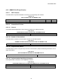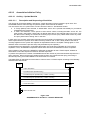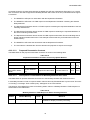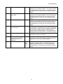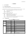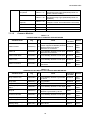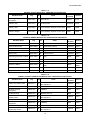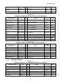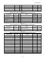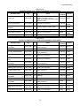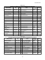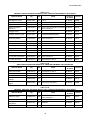
1
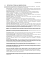
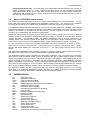
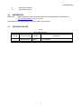
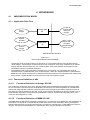
No. MIINM0010EA
DICOM CONFORMANCE STATEMENT
FOR
TOSHIBA NUCLEAR MEDICINE EQUIPMENT
GCA-9300R V1.1 SP0100J
(WORKFLOW MANAGEMENT)
© TOSHIBA MEDICAL SYSTEMS CORPORATION 2013
ALL RIGHTS RESERVED
No.MIINM0010EA
Trademarks
GCA-9300R is a trademark of Toshiba Medical Systems Corporation.
This manual may include trademarks or registered trademarks of other companies.
IMPORTANT!
(1)
No part of this manual may be copied or reprinted, in whole or in part,
without written permission.
(2)
The contents of this manual are subject to change without prior notice and
without our legal obligation.
*
C-1
No.MIINM0010EA
1. CONFORMANCE STATEMENT OVERVIEW
TM
Table 1-1 provides an overview of the network services supported by GCA-9300R .
Table 1-1
NETWORK SERVICES
SOP Classes
User of
Provider of
Service (SCU)
Service (SCP)
Yes
No
Yes
No
Transfer
NM Image Storage
Workflow Management
Modality Worklist Information Model – Find
*
i
No.MIINM0010EA
2. TABLE OF CONTENTS
1.
CONFORMANCE STATEMENT OVERVIEW ............................................................. i
2.
TABLE OF CONTENTS ............................................................................................. a
3.
INTRODUCTION ........................................................................................................ 1
3.1
AUDIENCE ........................................................................................................................................... 1
3.2
REMARKS ........................................................................................................................................... 1
3.3
DEFINITIONS, TERMS AND ABBREVIATIONS ................................................................................ 2
3.4
Basics of DICOM Communication .................................................................................................... 3
3.5
ABBREVIATIONS ................................................................................................................................ 3
3.6
REFERENCES ..................................................................................................................................... 4
3.7
REVISION HISTORY ........................................................................................................................... 4
4.
NETWORKING ........................................................................................................... 5
4.1
IMPLEMENTATION MODEL ............................................................................................................... 5
4.1.1
Application Data Flow ................................................................................................................... 5
4.1.2
Functional Definition of AEs .......................................................................................................... 5
4.1.3
Sequencing of Real-World Activities ............................................................................................. 6
4.2
AE SPECIFICATIONS ......................................................................................................................... 7
4.2.1
Storage SCU AE Specification ...................................................................................................... 7
4.2.2
MWM SCU AE Specification ....................................................................................................... 10
4.3
NETWORK INTERFACES ................................................................................................................. 16
4.3.2
Additional Protocols .................................................................................................................... 16
4.4
CONFIGURATION ............................................................................................................................. 16
4.4.1
AE Title/Presentation Address Mapping ..................................................................................... 16
5.
SUPPORT OF CHARACTER SETS ......................................................................... 17
6.
SECURTIY................................................................................................................ 18
7.
ANNEXES ................................................................................................................ 19
7.1
IOD CONTENTS ................................................................................................................................ 19
7.1.1
Created SOP Instances .............................................................................................................. 19
7.1.2
USED FIELDS IN RECEIVED IOD BY APPLICATION............................................................... 29
7.1.3
Attribute Mapping ........................................................................................................................ 29
7.1.4
Coerced/Modified Fields ............................................................................................................. 29
7.2
DATA DICTIONARY OF PRIVATE ATTRIBUTES ............................................................................ 30
7.3
CONTROLLED TERMINOLOGY AND TEMPLATES ....................................................................... 30
7.4
GRAYSCALE IMAGE CONSISTENCY ............................................................................................. 30
7.5
STANDARD EXTENDED/SPECIALIZED/PRIVATE SOP CLASSES ............................................... 30
7.6
PRIVATE TRANSFER SYNTAXES ................................................................................................... 30
a
*
No.MIINM0010EA
3. INTRODUCTION
3.1
AUDIENCE
This document is written for the people that need to understand how GCA9300R will integrate into their
healthcare facility.
This includes both those responsible for overall imaging network policy and architecture, as well as
integrators who need to have a detailed understanding of the DICOM features of the product.
This document contains some basic DICOM definitions so that any reader may understand how this product
implements DICOM features.
However, integrators are expected to fully understand all the DICOM terminology, how the tables in this
document relate to the product’s functionality, and how that functionality integrates with other devices that
support compatible DICOM features.
3.2
REMARKS
DICOM, by itself, does not guarantee interoperability. However, the Conformance Statement facilitates a
first-level validation for interoperability between different applications supporting the same DICOM
functionality.
This Conformance Statement is not intended to replace validation with other DICOM equipment to ensure
proper exchange of information intended.
The scope of this Conformance Statement is to facilitate communication with Toshiba Medical Systems and
other vendors’ Medical equipment. The Conformance Statement should be read and understood in
conjunction with the DICOM Standard [DICOM]. However, by itself it is not guaranteed to ensure the desired
interoperability and a successful interconnectivity.
The user should be aware of the following important issues:
— The comparison of different conformance statements is the first step towards assessing interconnectivity
between Toshiba Medical Systems and non-Toshiba Medical Systems equipment.
— Test procedures should be defined to validate the desired level of connectivity.
— The DICOM standard will evolve to meet the users’ future requirements. Toshiba Medical Systems is
actively involved in developing the standard further and therefore reserves the right to make changes to
its products or to discontinue its delivery.
1
No.MIINM0010EA
3.3
DEFINITIONS, TERMS AND ABBREVIATIONS
Informal definitions are provided for the following terms used in this Conformance Statement. The DICOM
Standard is the authoritative source for formal definitions of these terms.
Abstract Syntax – the information agreed to be exchanged between applications, generally equivalent
to a Service/Object Pair (SOP) Class. Examples: Verification SOP Class, Modality Worklist Information
Model Find SOP Class, Nuclear Medicine Image Storage SOP Class.
Application Entity (AE) – an end point of a DICOM information exchange, including the DICOM
network or media interface software; i.e., the software that sends or receives DICOM information
objects or messages. A single device may have multiple Application Entities
Application Entity Title – the externally known name of an Application Entity, used to identify a
DICOM application to other DICOM applications on the network.
Application Context – the specification of the type of communication used between Application
Entities. Example: DICOM network protocol.
Association – a network communication channel set up between Application Entities.
Attribute – a unit of information in an object definition; a data element identified by a tag. The
information may be a complex data structure (Sequence), itself composed of lower level data
elements. Examples: Patient ID (0010,0020), Accession Number (0008,0050), Photometric
Interpretation (0028,0004), Procedure Code Sequence (0008,1032).
Information Object Definition (IOD) – the specified set of Attributes that comprise a type of data
object; does not represent a specific instance of the data object, but rather a class of similar data
objects that have the same properties. The Attributes may be specified as Mandatory (Type 1),
Required but possibly unknown (Type 2), or Optional (Type 3), and there may be conditions associated
with the use of an Attribute (Types 1C and 2C). Examples: NM Image IOD
Module – a set of Attributes within an Information Object Definition that are logically related to each
other. Example: Patient Module includes Patient Name, Patient ID, Patient Birth Date, and Patient Sex
Negotiation – first phase of Association establishment that allows Application Entities to agree on the
types of data to be exchanged and how that data will be encoded.
Presentation Context – the set of DICOM network services used over an Association, as negotiated
between Application Entities; includes Abstract Syntaxes and Transfer Syntaxes.
Protocol Data Unit (PDU) – a packet (piece) of a DICOM message sent across the network. Devices
must specify the maximum size packet they can receive for DICOM messages.
Security Profile – a set of mechanisms, such as encryption, user authentication, or digital signatures,
used by an Application Entity to ensure confidentiality, integrity, and/or availability of exchanged
DICOM data
Service Class Provider (SCP) – role of an Application Entity that provides a DICOM network service;
typically, a server that performs operations requested by another Application Entity (Service Class
User). Examples: Picture Archiving and Communication System (image storage SCP, and image
query/retrieve SCP), Radiology Information System (modality worklist SCP)
Service Class User (SCU) – role of an Application Entity that uses a DICOM network service; typically,
a client. Examples: imaging modality (image storage SCU, and modality worklist SCU)
Service/Object Pair (SOP) Class – the specification of the network or media transfer (service) of a
particular type of data (object); the fundamental unit of DICOM interoperability specification. Examples:
Nuclear Medicine Image Storage Service.
Tag – a 32-bit identifier for a data element, represented as a pair of four digit hexadecimal numbers,
the “group” and the “element”. If the “group” number is odd, the tag is for a private
(manufacturer-specific) data element. Examples: (0010,0020) [Patient ID], (07FE,0010) [Pixel Data].
Transfer Syntax – the encoding used for exchange of DICOM information objects and messages.
Examples: little endian explicit value representation.
Unique Identifier (UID) – a globally unique “dotted decimal” string that identifies a specific object or a
class of objects; an ISO-8824 Object Identifier. Examples: Study Instance UID, SOP Class UID, SOP
Instance UID
2
No.MIINM0010EA
Value Representation (VR) – the format type of an individual DICOM data element, such as text, an
integer, a person’s name, or a code. DICOM information objects can be transmitted with either
explicit identification of the type of each data element (Explicit VR), or without explicit identification
(Implicit VR); with Implicit VR, the receiving application must use a DICOM data dictionary to look up
the format of each data element.
3.4
Basics of DICOM Communication
This section describes terminology used in this Conformance Statement for the non-specialist. The key
terms used in the Conformance Statement are highlighted in italics below. This section is not a substitute
for training about DICOM, and it makes many simplifications about the meanings of DICOM terms.
Two Application Entities (devices) that want to communicate with each other over a network using DICOM
protocol must first agree on several things during an intial network “handshake”. One of the two devices must
initiate an Association (a connection to the other device), and ask if specific services, information, and
encoding can be supported by the other device (Negotiation).
DICOM specifes a number of network services and types of information objects, each of which is called an
Abstract Syntax for the Negotiation. DICOM also specifes a variety of methods for encoding data, denoted
Transfer Syntaxes. The Negotiation allows the initiating Application Entity to propose combinations of
Abstract Syntax and Transfer Syntax to be used on the Association; these combinations are called
Presentation Contexts. The receiving Application Entity accepts the Presentation Contexts it supports.
For each Presentation Context, the Association Negotiation also allows the devices to agree on Roles –
which one is the Service Class User (SCU - client) and which is the Service Class Provider (SCP - server).
Normally the device initiating the connection is the SCU, i.e., the client system calls the server, but not
always.
The Association Negotiation finally enables exchange of maximum network packet (PDU) size, security
information, and network service options (called Extended Negotiation information).
The Application Entities, having negotiated the Association parameters, may now commence exchanging
data. Common data exchanges include queries for worklists and lists of stored images, transfer of image
objects and analyses (structured reports), and sending images to film printers. Each exchangeable unit of
data is formatted by the sender in accordance with the appropriate Information Object Definition, and sent
using the negotiated Transfer Syntax. There is a Default Transfer Syntax that all systems must accept, but it
may not be the most efficient for some use cases. Each transfer is explicitly acknowledged by the receiver
with a Response Status indicating success, failure, or that query or retrieve operations are still in process.
Two Application Entities may also communicate with each other by exchanging media (such as a CD-R).
Since there is no Association Negotiation possible, they both use a Media Application Profile that specifies
“pre-negotiated” exchange media format, Abstract Syntax, and Transfer Syntax.
3.5
ABBREVIATIONS
AE
AET
CD-R
CSE
DICOM
HIS
IOD
ISO
LUT
MSPS
MWL
NM
O
PDU
R
RIS
SCP
SCU
SOP
SPS
TCP/IP
Application Entity
Application Entity Title
Compact Disk Recordable
Customer Service Engineer
Digital Imaging and Communications in Medicine
Hospital Information System
Information Object Definition
International Organization for Standards
Look-up Table
Modality Scheduled Procedure Step
Modality Worklist
Nuclear Medicine
Optional (Key Attribute)
Protocol Data Unit
Required (Key Attribute)
Radiology Information System.
Service Class Provider
Service Class User
Service-Object Pair
Scheduled Procedure Step
Transmission Control Protocol/Internet Protocol
3
No.MIINM0010EA
U
VR
3.6
Unique (Key Attribute)
Value Representation
REFERENCES
NEMA PS3
Digital Imaging and Communications in Medicine (DICOM) Standard, available free at
http://medical.nema.org/ PS 3.1-18、2011
GCA9300R Gamma Camera Image Acquisition System User’s Manual
3.7
REVISION HISTORY
Table
REVISION HISTORY
Document
Version
*
Date of Issue
December 2014
Author
Description
TMSC
V1.1 SP0100J
4
No.MIINM0010EA
4. NETWORKING
4.1
IMPLEMENTATION MODEL
4.1.1 Application Data Flow
Send
Images
Storage SCU
AE
Remote AE
Receives
Images
MWM SCU
AE
Remote AE
Provides
Worklist Items
Update
Worklist
Acquire
Images
DICOM Standard Interface
Figure 4.1-1
APPLICATION DATA FLOW DIAGRAM
— The Storage SCU AE sends images to a remote AE. It is associated with the local real-world activity
“Send Images”. “Send Images” is performed upon user request for each study completed or for specific
images selected. When activated by user’s settings (auto-send), each marked set of images can be
immediately stored to a preferred destination.
— The MWM SCU AE receives Worklist information from a remote AE. It is associated with the local
real-world activity “Update Worklist” and “Acquire Images”. When the “Update Worklist” is performed the
MWM SCU AE queries a remote AE for worklist items and provides the set of worklist items matching the
query request. ”Update Worklist” is performed as a result of an operator request.
4.1.2 Functional Definition of AEs
4.1.2.1
Functional Definition of Storage SCU AE
The existence of a send-job queue entry with associated network destination will activate the Storage SCU
AE. An Association request is sent to the destination AE and upon successful negotiation of a Presentation
Context the image transfer is started. If the association cannot be opened, the related send-job is set to an
error state and can be restarted by the user via job control interface. By default, the Storage AE will not try to
initiate another association for this send-job automatically. However, an automatic retry (retry-timer, retrycount) can be configured by a CSE.
4.1.2.2
Functional Definition of MWM SCU AE
The MWM SCU AE attempts to download a worklist from a remote node. If the MWM SCU AE establishes an
Association to a remote AE, it will transfer all worklist items via the open Association. During receiving the
worklist response items are counted and the query processing is canceled if the configurable limit of items is
reached. The results will be displayed in a separate list, which may be cleared by the operator.
5
No.MIINM0010EA
4.1.3
Sequencing of Real-World Activities
Storage
SCU
MWM
SCU
Department
Scheduler
Process
WorkStation
1. Query Worklist
2. Receive Worklist
3. Select Workitem (MPSP)
4. Start acquisition
5. Acquire Images
6. Complete acquisition
7. Store Acquired Images
Figure 4.1-2
SEQUENCING CONSTRAINTS
Under typical scheduled workflow conditions the sequencing constraints illustrated in Figure 4.1-2 apply:
1. Query Worklist
2. Receive Worklist of Modality Scheduled Procedure Steps (MSPS)
3. Select Workitem (MSPS) from Worklist
4. Start acquisition
5. Acquire Images
6. Complete acquisition
7. Store Acquire Images
Other workflow situations (e.g. unscheduled procedure steps) will have other sequencing constraints. Some
activities may be omitted according to situations.
6
No.MIINM0010EA
4.2
AE SPECIFICATIONS
4.2.1 Storage SCU AE Specification
4.2.1.1
SOP Classes
The Storage SCU AE provides Standard Conformance to the following SOP Classes:
Table 4.2-1
SOP CLASSES FOR THE STORAGE SCU AE
SOP Class Name
NM Image Storage
4.2.1.2
SOP Class UID
1.2.840.10008.5.1.4.1.1.20
SCU
Yes
SCP
No
Association Policies
4.2.1.2.1 General
The DICOM standard application context name for DICOM 3.0 is always proposed:
Table 4.2-2
DICOM APPLICATION CONTEXT FOR THE STORAGE SCU AE
Application Context Name
1.2.840.10008.3.1.1.1
4.2.1.2.2 Number of Associations
The Storage SCU AE can initiates one Associations at a time for each destination to which a transfer request
is being processed in the active job queue list. Only one job will be active at a time, the other remains pending
until the active job is completed or failed.
Table 4.2-3
NUMBER OF ASSOCIATIONS INITIATED FOR THE STORAGE SCU AE
Maximum number of simultaneous Associations
1
4.2.1.2.3 Asynchronous Nature
The Storage SCU AE does not support asynchronous communication (multiple outstanding transactions over
a single Association).
Table 4.2-4
ASYNCHRONOUS NATURE FOR THE STORAGE SCU AE
Maximum number of outstanding asynchronous transactions
1
4.2.1.2.4 Implementation Identifying Information
The implementation information for the Storage SCU AE is:
Table 4.2-5
DICOM IMPLEMENTATION CLASS AND VERSION FOR THE STORAGE SCU AE
Implementation Class UID
1.2.392.200036.9116.5.7.10
Implementation Version Name
TM_NM_DCM_V3.0
7
No.MIINM0010EA
4.2.1.3
Association Initiation Policy
4.2.1.3.1 Activity – Send Images
4.2.1.3.1.1
Description and Sequencing of Activities
A user can select previously acquired images and request them to be sent to multiple destinations. Each
request is forwarded to the job queue and processed individually.
In addition, there exists an “auto-send” option that is triggered by the end of acquisition. When the
“auto-send” option is active, each acquired instance or set of instances is stored in the local database as
usual and it is also forwarded to the network job queue for a preconfigured auto-send target destination. It
can be configured how many and which are the destinations where the instances are automatically sent to
(see GCA9300R Gamma Camera Image Acquisition System User’s Manual).
The Storage AE is invoked by the job control interface that is responsible for processing network archival
tasks. The job consists of data describing the instances marked for storage and the destination. An internal
daemon process triggered by a job for a specific network destination initiates a C-STORE request to store
images. If the process successfully establishes an Association to a remote Application Entity, it will transfer
each marked instance one after another via the open Association. Status of the transfer is reported through
the job control interface. Only one job will be active at a time. If the C-STORE Response from the remote
Application contains a status other than Success or Warning, the Association is aborted and the related Job
is switched to a failed state. It can be restarted, if configured, by automated retry.
The Storage SCU AE attempts to initiate a new Association in order to issue a Storage request (C-STORE). If
the job contains multiple images then multiple C-STORE requests will be issued over the same Association.
Storage SCU
AE
Process
WorkStation
1. Open Association
2. C-STORE Request (Storage)
3. Close Association
Figure 4.2-1
SEQUENCING OF ACTIVITY – SEND IMAGES
A possible sequence of interactions between the Storage SCU AE and Process Workstaton is illustrated in
the Figure above:
1. The Storage SCU AE opens an Association with the Process Workstation
2. Acquired images are transmitted to the Process Workstation using a Storage request (C-STORE)
and the Process Workstation replies with a C-STORE response (status success).
3. The Storage SCU AE closes the Association with the Process Workstation.
8
No.MIINM0010EA
4.2.1.3.1.2
Proposed Presentation Contexts
The Storage SCU AE is capable of proposing the Presentation Contexts shown in the following table:
Table 4.2-6
PROPOSED PRESENTATION CONTEXTS FOR ACTIVITY SEND IMAGES
Presentation Context Table
Abstract Syntax
Name
UID
NM Image Storage
4.2.1.3.1.3
Transfer Syntax
Name List
1.2.840.10008.5.1.4.
Implicit VR Little Endian
1.1.20
Ext.
UID List
1.2.840.10008.1.2
Role
Neg.
SCU None
SOP Specific Conformance for Storage SOP Classes
The Storage SCU AE provides standard conformance to the Storage Service Class as an SCU.
The behavior of Storage SCU AE when encountering status codes in a C-STORE response is summarized in
the Table below:
Table 4.2-7
STORAGE C-STORE RESPONSE STATUS HANDLING BEHAVIOR
Service
Status
Success
Further Meaning
Success
Status
Code
0000
Behavior
The SCP has successfully stored the SOP Instance. If all
SOP Instances in a send job have status success then the
job is marked as complete.
The behavior of Storage SCU AE during communication failure is summarized in the Table below:
Table 4.2-8
STORAGE COMMUNICATION FAILURE BEHAVIOR
Exception
Behavior
Timeout
The Association is aborted using A-ABORT and the
send job is marked as failed. The reason is logged
and the job failure is reported to the user via the job
control application.
Association aborted by the SCP or network layers
The send job is marked as failed. The reason is
logged and the job failure is reported to the user via
the job control application.
The system can be configured to automatically resend failed jobs. The delay between resending failed jobs
and the number of retries is also configurable.
If the image transfer fails, the Storage SCU AE will retry this send-job automatically. The delay between
resending failed jobs and the number of retries is also configurable.
The contents of Nuclear Medicine Image Storage SOP Instances created by GCA9300R conform to the
DICOM Nuclear Medicine Image IOD definition and are described in section 7.1.
9
No.MIINM0010EA
4.2.2 MWM SCU AE Specification
4.2.2.1
SOP Classes
The MWM SCU AE provides Standard Conformance to the following SOP Classes:
Table 4.2-9
SOP CLASSES FOR THE MWM SCU AE
SOP Class Name
Modality Worklist Information Model – FIND
4.2.2.2
SOP Class UID
1.2.840.10008.5.1.4.31
SCU
Yes
SCP
No
Association Policies
4.2.2.2.1 General
The DICOM standard application context name for DICOM 3.0 is always proposed:
Table 4.2-10
DICOM APPLICATION CONTEXT FOR THE MWM SCU AE
Application Context Name
1.2.840.10008.3.1.1.1
4.2.2.2.2 Number of Associations
The MWM SCU AE initiates one Association at a time for a Worklist request.
Table 4.2-11
NUMBER OF ASSOCIATIONS INITIATED FOR THE MWM SCU AE
Maximum number of simultaneous Associations
1
4.2.2.2.3 Asynchronous Nature
The MWM SCU AE does not support asynchronous communication (multiple outstanding transactions over a
single Association).
Table 4.2-12
ASYNCHRONOUS NATURE FOR THE MWM SCU AE
Maximum number of outstanding asynchronous transactions
1
4.2.2.2.4 Implementation Identifying Information
The implementation information for this Application Entity is:
Table 4.2-13
DICOM IMPLEMENTATION CLASS AND VERSION FOR THE MWM SCU AE
Implementation Class UID
1.2.392.200036.9116.5.7.10
Implementation Version Name
TM_NM_DCM_V3.0
10
No.MIINM0010EA
4.2.2.3
Association Initiation Policy
4.2.2.3.1 Activity – Update Worklist
4.2.2.3.1.1
Description and Sequencing of Activities
The request for a Worklist Update is interactive. A brief description of the procedure is given here. See
GCA9300R Gamma Camera Image Acquisition System User's Manual for details.
The user selects one of 2 options from a list box and then clicks on “Get Worklist” button.
a. If “Today (default)” was selected, a default MWL server AE is queried immediately for procedures
scheduled for the present day.
b. If “Other” was selected, a form opens to enter search criteria, including the MWL server AE. The
most recently used search criteria stay as default value till they are changed again in this form. Only
the data from the dialog are inserted as matching keys into the query. Blank fields match any value.
The query starts when clicking “OK” in the form.
In both cases, the operator waits while information arrives and fills in Scheduled list. The number of received
and accepted entries is reported. Items without a Study Instance UID or with a Study Instance UID that is
currently registered in the system are rejected. No duplicated entries are accepted. Clicking again on “Get
Worklist” does not erase the previous list (it may be deleted by the operator).
Accepted entries are displayed in a separate table till the user send them individually to Current list for
acquisition. Then, GCA9300R incorporates worklist items into the local database for future acquisition.
Upon initiation of the request, the MWM SCU AE builds an Identifier for the C-FIND request, initiates an
Association to send the request and waits for Worklist responses.
To protect the system from overflow, GCA9300R will limit the number of processed worklist responses to a
given maximum. During receiving the worklist response items are counted and the query processing is
canceled by issuing a C-FIND-CANCEL if the limit of items is reached.
The MWM SCU AE will initiate an Association in order to issue a C-FIND request according to the Modality
Worklist Information Model.
MWM
SCU
Department
Scheduler
1. Open Association
2. C-FIND Request (Worklist Query)
3. C-FIND Response (Worklist Item) – Status = Pending
4. C-FIND Response (Worklist Item) – Status = Pending
5. C-FIND Response – Status = Success
6. Close Association
7. Select Worklist Item
Figure 4.2-2
SEQUENCING OF ACTIVITY – UPDATE WORKLIST
11
No.MIINM0010EA
A possible sequence of interactions between the MWM SCU AE and a Department Scheduler (e.g. a device
such as a RIS or HIS which supports the Modality Worklist SOP Class as an SCP) is illustrated in the Figure
2.2-2 above:
1. The MWM SCU AE opens an association with the Department Scheduler
2. The MWM SCU AE sends a C-FIND request to the Department Scheduler containing the Worklist
Query attributes.
3. The Department Scheduler returns a C-FIND response containing the requested attributes of the first
matching Worklist Item.
4. The Department Scheduler returns another C-FIND response containing the requested attributes of
the second matching Worklist Item.
5. The Department Scheduler returns another C-FIND response with status Success indicating that no
further matching Worklist Items exist. This example assumes that only 2 Worklist items match the
Worklist Query.
6. The MWM SCU AE closes the association with the Department Scheduler.
7. The user selects a Worklist Item from the Worklist and prepares to acquire new images.
4.2.2.3.1.2
Proposed Presentation Contexts
The MWM SCU AE will propose Presentation Contexts as shown in the following table:
Table 4.2-14
Proposed Presentation Contexts for Activity Update Worklist
Presentation Context Table
Abstract Syntax
Transfer Syntax
Name
UID
Name List
Modality Worklist
Information Model –
FIND
1.2.840.10008.5.1.
4.31
Implicit VR Little Endian
4.2.2.3.1.3
Ext.
UID List
1.2.840.10008.1.2
Role
Neg.
SCU
None
SOP Specific Conformance for Modality Worklist SOP Class
The MWM SCU AE provides standard conformance to the Modality Worklist SOP Class as an SCU.
In a Modality Worklist C-FIND, if response status codes received by GCA9300R are any other than "Success"
or "Pending", a message “Error in MWL query” will appear on the user interface.
The behavior of the MWM SCU when encountering status codes in a Modality Worklist C-FIND response is
summarized in the Table below.
Table 4.2-15
Modality Worklist C-FIND Response Status Handling Behavior
Service
Status
Further Meaning
Success Matching is complete
Status
Code
0000
Behavior
The SCP has completed the matches. Worklist items are
available for display or further processing.
12
No.MIINM0010EA
Refused
Out of Resources
A700
The Association is aborted using A-ABORT and the
worklist query is marked as failed. The status meaning
is logged and reported to the user if an interactive query.
Any additional error information in the Response will be
logged.
Failed
Identifier does not match
SOP Class
A900
The Association is aborted using A-ABORT and the
worklist query is marked as failed. The status meaning is
logged and reported to the user if an interactive query.
Any additional error information in the Response will be
logged.
Failed
Unable to Process
Cxxx
The Association is aborted using A-ABORT and the
worklist query is marked as failed. The status meaning is
logged and reported to the user if an interactive query.
Any additional error information in the Response will be
logged.
Cancel
Matching terminated due to FE00
Cancel request
If the query was cancelled due to too may worklist items
then the SCP has completed the matches. Worklist items
are available for display or further processing. Otherwise,
the Association is aborted using A-ABORT and the
worklist query is marked as failed. The status meaning
is logged and reported to the user if an interactive query.
Pending
Matches are continuing
FF00
The worklist item contained in the Identifier is collected for
later display or further processing.
Pending
Matches are continuing –
Warning that one or more
Optional Keys were not
supported
FF01
The worklist item contained in the Identifier is collected for
later display or further processing. The status meaning is
logged only once for each C-FIND operation.
*
*
Any
other
status
code.
The Association is aborted using A-ABORT and the
worklist is marked as failed. The status meaning is
logged and reported to the user if an interactive query.
Any additional error information in the Response will be
logged.
13
No.MIINM0010EA
The behavior of the MWM SCU AE during communication failure is summarized in the Table below.
Table 4.2-16
MODALITY WORKLIST COMMUNICATION FAILURE BEHAVIOR
Exception
Behavior
Timeout
The Association is aborted using A-ABORT and the worklist query is marked
as failed. The reason is logged and reported to the user if an interactive
query.
Association aborted by the
SCP or network layers
The worklist query is marked as failed. The reason is logged and reported to
the user if an interactive query.
Acquired images will always use the Study Instance UID specified for the Scheduled Procedure Step (if
available). Scheduled Procedure Steps without a Study Instance UID or with a Study Instance UID that is
already registered in GCA9300R data base are not accepted. If an acquisition is unscheduled, a Study
Instance UID will be generated locally.
The Table below provides a description of the MWM SCU AE Worklist Request Identifier and specifies the
attributes that are copied into the images. Unexpected attributes returned in a C-FIND response are ignored.
Requested return attributes not supported by the SCP are set to have no value. Non-matching responses
returned by the SCP due to unsupported optional matching keys are ignored. No duplicate entries are
accepted.
Table 4.2-17
WORKLIST REQUEST IDENTIFIER
Module Name
Attribute Name
Tag
VR
M
R
(0040,0100)
(0040,0001)
(0040,0010)
(0040,0011)
(0040,0002)
(0040,0003)
(0040,0006)
(0040,0007)
(0040,0008)
(0040,0009)
(0040,0400)
(0008,0060)
(0032,1070)
(0040,0012)
SQ
AE
LO
SH
DA
TM
PN
SH
SQ
SH
LT
CS
LO
LO
(0040,1001)
(0032,1060)
(0020,000D)
(0040,1003)
(0040,1004)
SH
LO
UI
SH
LO
(0032,1032)
(0008,0090)
(0008,0050)
PN
PN
SH
(0038,0010)
LO
x
(0038,0300)
LO
x
D
IOD
Scheduled Procedure Step
Scheduled Procedure Step Sequence
> Scheduled Station AE Title
> Scheduled Station Name
> Scheduled Procedure Step Location
> Scheduled Procedure Step Start Date
> Scheduled Procedure Step Start Time
> Scheduled Performing Physician’s Name
> Scheduled Procedure Step Description
> Scheduled Protocol Code Sequence
> Scheduled Procedure Step ID
> Comments on Scheduled Procedure Step
> Modality
> Requested Contrast Agent
> Pre-Medication
x
x/r
x
x
x
x
x
x
x
x
x
x
x
x
x
x
x
x
x
x
x
x
x
x
x
x
x
x
Requested Procedure
Requested Procedure ID
Requested Procedure Description
Study Instance UID
Requested Procedure Priority
Patient Transport Arrangements
x
x
x
x
x
x
x
x
x
x
x
x
x
x
x
x
Imaging Service Request
Requesting Physician
Referring Physician's Name
Accession Number
x
Visit Identification
Admission ID
Visit Status
Current Patient Location
14
x
x
x
No.MIINM0010EA
Patient Identification
Patient’s Name
Patient ID
(0010,0010)
(0010,0020)
PN
LO
Patient Data Confidentiality Constraint Description
Patient’s Birth Date
Patient’s Sex
Patient’s Size
Patient’s Weight
Patient Comment
Patient Medical
(0040,3001)
(0010,0030)
(0010,0040)
(0010,1020)
(0010,1030)
(0010,4000)
Medical Alerts
Contrast Allergies
Pregnancy Status
Last Menstrual Date
Special Needs
Patient State
(0010,2000)
(0010,2110)
(0010,21C0)
(0010,21D0)
(0038,0050)
(0038,0500)
x
x
x
x
x
x
x
x
LO
DA
CS
DS
DS
LT
x
x
x
x
x
x
x
x
x
x
x
x
x
x
x
x
LO
LO
US
DA
LO
LO
x
x
x
x
x
x
Patient Demographic
The above table should be read as follows:
Module Name:
The name of the associated module for supported worklist attributes.
Attribute Name:
Attributes supported to build the MWM SCU AE Worklist Request Identifier.
Tag:
DICOM tag for this attribute.
VR:
DICOM VR for this attribute.
M:
Matching keys for Worklist Update. An "S" will indicate that the MWM SCU AE will
supply an attribute value for Single Value Matching. An “x” indicates that GCA9300R
will supply this attribute as matching key, if entered in the Query Patient Worklist
dialog (for example, the Patient Name can be entered thereby restricting Worklist
responses to Procedure Steps scheduled for the patient). “x/r” means that the
matching key may be a single value or a range.
R:
Return keys. An "x" will indicate that the MWM SCU AE will supply this attribute as
Return Key with zero length for Universal Matching.
D:
Displayed keys. An “x” indicates that this worklist attribute is displayed to the user in
Scheduled list or in its detail forms.
IOD:
An "x" indicates that this Worklist attribute is included into all Object Instances
created during performance of the related Procedure Step.
4.2.2.3.2
Activity – Acquire Images
Acquisition cannot proceed directly from Scheduled procedures list received from MWL server. The operator
has to send them individually into Current list. Optionally, an entry may be created from scratch interactively in
Current list.
To acquire images, the operator selects an entry from Current list, assigns it to an acquisition protocol and
acquires one or more images depending on the selected acquisition protocol.
When finished, images are always automatically saved into the acquisition system hard disk. They may be
sent also to one or more storage devices (configurable).
See GCA9300R Gamma Camera Image Acquisition System User’s Manual for details
4.2.2.4
Association Acceptance Policy
The MWM SCU AE does not accept Associations.
15
No.MIINM0010EA
4.3
NETWORK INTERFACES
4.3.1.1
Physical Network Interface
This Product supports a single network interface. One of the following physical network interfaces will be
available depending on installed hardware options:
Table 4.3-1
SUPPORTED PHYSICAL NETWORK INTERFACES
Ethernet 100baseT
Ethernet 10baseT
4.3.2 Additional Protocols
None.
4.4
CONFIGURATION
4.4.1 AE Title/Presentation Address Mapping
4.4.1.1
Local AE Titles
All local applications use the AE Titles and TCP/IP Ports configured via the Service/Installation Tool. The
Field Service Engineer can configure the TCP Port via the Service/Installation Tool.
Table 4.4-1
AE TITLE CONFIGURATION TABLE
Application Entity
MWM SCU
Storage SCU
4.4.1.2
Default AE Title
GCA9300R
Default TCP/IP Port
Not Applicable
Remote AE Title/Presentation Address Mapping
The AE Titles, host names and port numbers of remote applications are configured using the Configuration
file.
16
No.MIINM0010EA
5. SUPPORT OF CHARACTER SETS
This product supports the following character sets:
・ ISO-IR 100 (Latin alphabet No.1)
Supplementary set of ISO 8859
17
No.MIINM0010EA
6. SECURTIY
This product does not support any specific security measures.
It is assumed that the product is used within a secured environment. It is assumed that a secured
environment includes at a minimum:
a. Firewall or router protections to ensure that only approved external hosts have network access to
the product.
b. Firewall or router protections to ensure that the product only has network access to approved
external hosts and services.
c.
Any communication with external hosts and services outside the locally secured environment use
appropriate secure network channels (e.g. such as a Virtual Private Network (VPN))
Other network security procedures such as automated intrusion detection may be appropriate in some
environments. Additional security features may be established by the local security policy and are beyond the
scope of this conformance statement.
18
No.MIINM0010EA
7. ANNEXES
7.1
IOD CONTENTS
7.1.1 Created SOP Instances
Table 7.1-1 specifies the attributes of a NM Image transmitted by the Storage SCU AE.
The following tables use a number of abbreviations. The abbreviations used in the “Presence of …” column
are:
VNAP
Value Not Always Present (attribute sent zero length if no value is present)
ANAP
Attribute Not Always Present
ALWAYS
Always Present
EMPTY
Attribute is sent without a value
The abbreviations used in the “Source” column:
MWL
the attribute value source is from Modality Worklist
USER
the attribute value source is from User input
AUTO
the attribute value is generated automatically
MPPS
the attribute value is the same as that use for Modality Performed Procedure Step
CONFIG
the attribute value source is a configurable parameter
7.1.1.1
NM Image IOD
Table 7.1-1
IOD OF CREATED NM IMAGE SOP INSTANCES
IE
Module
Reference
Presence of Module
Patient
Patient
Table 7.1-2
ALWAYS
Study
General Study
Table 7.1-3
ALWAYS
Patient Study
Table 7.1-4
ALWAYS
General Series
Table 7.1-5
ALWAYS
NM/PET Patient
Orientation
Table 7.1-6
ALWAYS
Equipment
General Equipment
Table 7.1-7
ALWAYS
Image
General Image
Table 7.1-8
ALWAYS
Image Pixel
Table 7.1-9
ALWAYS
NM Image Pixel
Table 7.1-10
ALWAYS
Multi-frame
Table 7.1-11
ALWAYS
NM Multi-frame
Table 7.1-12
ALWAYS
NM Image
Table 7.1-13
ALWAYS
NM Isotope
Table 7.1-14
ALWAYS
NM Detector
Table 7.1-15
NM TOMO
Acquisition
Table 7.1-16
ALWAYS
ANAP
(Required if Image Type (0008,0008) Value 3 is
TOMO, GATED TOMO.)
Series
19
No.MIINM0010EA
NM Multi-gated
Acquisition
Table 7.1-17
NM Phase
Table 7.1-18
7.1.1.2
ANAP
(Required if Image Type (0008,0008) Value 3 is
GATED, GATED TOMO.)
ANAP
(Required if Image Type (0008,0008) Value 3 is
DYNAMIC.)
ANAP
(If Organ is “None” this module dose not Present)
General Anatomy
Optional
Table 7.1-19
VOI LUT
Table 7.1-20
ALWAYS
SOP Common
Table 7.1-21
ALWAYS
Private Application
Table 7.1-22
ALWAYS
Common Modules
Table 7.1-2
PATIENT MODULE OF CREATED SOP INSTANCES
Attribute Name
Tag
VR
Value
Presence
of Value
Source
Patient’s Name
(0010,0010)
PN
From Modality Worklist or user input.
Values supplied via Modality Worklist
ALWAYS
will be entered as received.
Maximum 64 characters.
Patient ID
(0010,0020)
LO
From Modality Worklist or user input.
ALWAYS
Maximum 64 characters.
MWL/
USER
Patient’s Birth Date
(0010,0030)
DA
From Modality Worklist or user input
ALWAYS
MWL/
USER
Patient’s Sex
(0010,0040)
CS
From Modality Worklist or user input
ALWAYS
MWL/
USER
Patient Comments
(0010,4000)
LT
From User Input. Maximum 1024
characters.
VNAP
MWL/
USER
Presence
of Value
Source
MWL/
USER
Table 7.1-3
GENERAL STUDY MODULE OF CREATED SOP INSTANCES
Attribute Name
Tag
VR
Value
From Modality Worklist or generated
by device
ALWAYS
MWL/
AUTO
DA <yyyymmdd>
ALWAYS
AUTO
(0008,0030)
TM <hhmmss.frac>
ALWAYS
AUTO
Referring Physician’s
Name
(0008,0090)
PN
From Modality Worklist or User Input VNAP
MWL/
USER
Study ID
(0020,0010)
SH
Requested Procedure ID from
Worklist or generated by device
VNAP
MWL/
AUTO
Accession Number
(0008,0050)
SH
From Modality Worklist or user input
VNAP
MWL/
USER
Study Description
(0008,1030)
LO
Comment text box in study list.
ALWAYS
USER
Physician(s) of Record
(0008,1048)
PN
Set to NULL
EMPTY
AUTO
Name of Physician(s)
Reading Study
(0008,1060)
PN
Set to NULL
EMPTY
AUTO
Study Instance UID
(0020,000D)
UI
Study Date
(0008,0020)
Study Time
20
No.MIINM0010EA
Table 7.1-4
PATIENT STUDY MODULE OF CREATED SOP INSTANCES
Attribute Name
Value
Presence
of Value
Tag
VR
Admitting Diagnosis
Description
(0008,1080)
LO
Set to NULL
EMTPY
AUTO
Patient’s Age
(0010,1010)
AS
Calculated from DoB input on base
of Study Date
ALWAYS
AUTO
Patient’s Size
(0010,1020)
DS
From Modality Worklist or user input
VNAP
MWL/
USER
Patient’s Weight
(0010,1030)
DS
From Modality Worklist or user input
VNAP
MWL/
USER
Source
Table 7.1-5
GENERAL SERIES MODULE OF CREATED SOP INSTANCES
Attribute Name
Tag
VR
Modality
(0008,0060)
Series Instance UID
CS
Value
Presence
of Value
Source
“NM”
ALWAYS
AUTO
(0020,000E) UI
Generated by device
ALWAYS
AUTO
Series Number
(0020,0011)
IS
Generated by device
ALWAYS
AUTO
Series Date
(0008,0021)
DA
<yyyymmdd>
ALWAYS
AUTO
Series Time
(0008,0031)
TM
<hhmmss.frac>
ALWAYS
AUTO
Performing Physician’s Name (0008,1050)
PN
From Modality Worklist or User
Input
VNAP
MWL/
USER
Protocol Name
(0018,1030)
LO
Taken from acquisition
ALWAYS
USER
Series Description
(0008,103E) LO
user input
VNAP
USER
Operator’s Name
(0008,1070)
PN
From Modality Worklist or User
Input
VNAP
Patient Position
(0018,5100)
CS
Taken from acquisition
ALWAYS
MWL/
USER
AUTO
Largest Pixel Value in Series
(0028,0109)
CS
Taken from acquisition
ALWAYS
AUTO
Table 7.1-6
NM/PET PATIENT ORIENTATION MODULE OF CREATED SOP INSTANCES
Tag
VR
Value
Presence
of Value
Patient Orientation Code
(0054,0410)
SQ
Zero or one item shall be included in
this sequence.
ALWAYS
AUTO
>Code Value
(0008,0100)
SH
Baseline CID 19.
VNAP
AUTO
>Coding Scheme
Designator
(0008,0102)
SH
“99SDM”
VNAP
AUTO
>Code Meaning
(0008,0104)
LO
Baseline CID 19.
VNAP
AUTO
>Patient Orientation
Modifier Code
(0054,0412)
SQ
Zero or one item shall be included in
this sequence.
ALWAYS
AUTO
>>Code Value
(0008,0100)
SH
Baseline CID 20.
VNAP
AUTO
>>Coding Scheme
Designator
(0008,0102)
SH
“99SDM”
VNAP
AUTO
>>Code Meaning
(0008,0104)
LO
Baseline CID 20.
VNAP
AUTO
Patient Gantry
Relationship Code
(0054,0414)
SQ
Zero or one item shall be included in
this sequence.
ALWAYS
AUTO
Attribute Name
21
Source
No.MIINM0010EA
>Code Value
(0008,0100)
SH
Baseline CID 21.
VNAP
AUTO
>Coding Scheme
Designator
(0008,0102)
SH
“99SDM”
VNAP
AUTO
>Code Meaning
(0008,0104)
LO
Baseline CID 21.
VNAP
AUTO
Table 7.1-7
GENERAL EQUIPMENT MODULE OF CREATED SOP INSTANCES
Attribute Name
Tag
VR
Value
Presence
of Value
Source
Manufacturer
(0008,0070)
LO
“TOSHIBA_MEC”
ALWAYS
AUTO
Institution Name
(0008,0080)
LO
From Configuration
VNAP
CONFIG
AUTO
Institution Address
(0008,0081)
ST
From Configuration
VNAP
CONFIG
AUTO
Station Name
(0008,1010)
SH
From Configuration
ALWAYS
CONFIG
Institution Department
Name
(0008,1040)
LO
From Configuration
VNAP
CONFIG
Manufacturer’s Model
Name
(0008,1090)
LO
GCA9300R
ALWAYS
AUTO
Device Serial Number
(0018,1000)
LO
From Configuration
VNAP
CONFIG
Software Version
(0018,1020)
LO
V1.00JR000 or later
ALWAYS
AUTO
Date of Last Calibration
(0018,1200)
DA
Taken from system last calibration
ALWAYS
AUTO
Time of Last Calibration
(0018,1201)
TM Taken from system last calibration
ALWAYS
AUTO
Table 7.1-8
GENERAL IMAGE MODULE OF CREATED SOP INSTANCES
Attribute Name
Tag
VR
Value
Presence
of Value
Source
Instance Number
(0020,0013)
IS
Generated by device
ALWAYS
AUTO
Content Date
(0008,0023)
DA
Generated by device
ALWAYS
AUTO
Content Time
(0008,0033)
TM Generated by device
ALWAYS
AUTO
Image Type
(0008,0008)
CS
Generated by device
ALWAYS
AUTO
Acquisition Date
(0008,0022)
DA
Generated by device
ALWAYS
AUTO
Acquisition Time
(0008,0032)
TM Generated by device
ALWAYS
AUTO
Image Comments
(0020,4000)
LT
EMPTY
AUTO
7.1.1.3
Set to NULL
NM Image Modules
Table 7.1-9
IMAGE PIXEL MODULE OF CREATED NM IMAGE SOP INSTANCES
Attribute Name
Value
Presence
of Value
Source
Tag
VR
Sample per Pixel
(0028,0002)
US
1
ALWAYS
AUTO
Photometric interpretation
(0028,0004)
CS
“MONOCHROME2”
ALWAYS
AUTO
Rows
(0028,0010)
US
ALWAYS
AUTO
Columns
(0028,0011)
US
ALWAYS
AUTO
Bits Allocated
(0028,0100)
US
16
ALWAYS
AUTO
Bits Stored
(0028,0101)
US
16
ALWAYS
AUTO
22
No.MIINM0010EA
High Bit
(0028,0102)
US
15
ALWAYS
AUTO
Pixel Representation
(0028,0103)
US
0
ALWAYS
AUTO
Smallest Image Pixel Value
(0028,0106)
US
Generated by device
ALWAYS
AUTO
Largest Image Pixel Value
(0028,0107)
US
Generated by device
ALWAYS
AUTO
Pixel Data
(7FE0,0010) OW Generated by device
ALWAYS
AUTO
Table 7.1-10
NM IMAGE PIXEL MODULE OF CREATED NM IMAGE SOP INSTANCES
Attribute Name
Value
Presence
of Value
Tag
VR
Sample per Pixel
(0028,0002)
US
1
ALWAYS
AUTO
Photometric interpretation
(0028,0004)
CS
“MONOCHROME2”
ALWAYS
AUTO
Bits Allocated
(0028,0100)
US
16
ALWAYS
AUTO
Bits Stored
(0028,0101)
US
16
ALWAYS
AUTO
High Bit
(0028,0102)
US
15
ALWAYS
AUTO
Pixel Spacing
(0028,0030)
DS
Generated by device
ALWAYS
AUTO
Source
Table 7.1-11
MULTI-FRAME MODULE OF CREATED NM IMAGE SOP INSTANCES
Attribute Name
Value
Presence
of Value
Source
Tag
VR
Number of Frames
(0028,0008)
IS
Taken from acquisition
ALWAYS
AUTO/
USER
Frame Increment Pointer
(0028,0009)
AT
Generated by device
ALWAYS
AUTO
Table 7.1-12
NM MULTI-FRAME MODULE OF CREATED NM IMAGE SOP INSTANCES
Attribute Name
Value
Presence
of Value
Tag
VR
Frame Increment Pointer
(0028,0009)
AT
Generated by device
ALWAYS
AUTO
Energy Window Vector
(0054,0010)
US
Generated by device
ALWAYS
AUTO
Number of Energy Windows
(0054,0011)
US
Taken from acquisition
ALWAYS
USER
Detector Vector
(0054,0020)
US
Generated by device
ALWAYS
USER
Number of Detectors
(0054,0021)
US
Taken from acquisition
ALWAYS
USER
Phase Vector
(0054,0030)
US
Generated by device
ANAP
AUTO
Number of Phases
(0054,0031)
US
Taken from acquisition
ANAP
USER
Rotation Vector
(0054,0050)
US
Generated by device
ANAP
AUTO
Number of Rotations
(0054,0051)
US
Taken from acquisition
ANAP
USER
R-R Interval Vector
(0054,0060)
US
Generated by device
ANAP
AUTO
Number of R-R Intervals
(0054,0061)
US
Taken from acquisition
ANAP
AUTO
Time Slot Vector
(0054,0070)
US
Generated by device
ANAP
AUTO
Number of Time Slots
(0054,0071)
US
Taken from acquisition
ANAP
AUTO
Angular View Vector
(0054,0090)
US
Generated by device
ANAP
AUTO
Time Slice Vector
(0054,0100)
US
Generated by device
ANAP
AUTO
23
Source
No.MIINM0010EA
Table 7.1-13
NM IMAGE MODULE OF CREATED NM IMAGE SOP INSTANCES
Attribute Name
Tag
VR
Value
Presence
of Value
Source
Image Type
(0008,0008)
CS
“ORIGINAL¥PRIMARY¥[VALUE3]”,
Where “VALUE3” is one of
ALWAYS
STATIC,DYNAMIC,GATED,TOMO,
GATED TOMO.
Counts Accumulated
(0018,0070)
IS
Taken from acquisition
ALWAYS
AUTO/
USER
Acquisition Termination
Condition
(0018,0071)
CS
“CTNS”,”MANU”,”TIME”,”TRIG”
ALWAYS
USER
Trigger Source or Type
(0018,1061)
LO
EKG (only gated and gated-tomo)
ANAP
AUTO
Actual Frame Duration
(0018,1242)
IS
Taken from acquisition
ANAP
AUTO/
USER
Corrected Image
(0028,0051)
CS
“UNIF”
ALWAYS
AUTO
AUTO
Table 7.1-14
NM ISOTOPE MODULE OF CREATED NM IMAGE SOP INSTANCES
Attribute Name
Value
Presence
of Value
Tag
VR
Energy Window
Information
(0054,0012)
SQ
Zero or one item shall be included
in this sequence.
ALWAYS
AUTO
>Energy Window Name
(0054,0018)
SH
Taken from acquisition
ALWAYS
AUTO
>Energy Window Range
(0054,0013)
SQ
Zero or one item shall be included
in this sequence.
ALWAYS
AUTO
>>Energy Window Lower
Limit
(0054,0014)
DS
Taken from acquisition
ALWAYS
USER
>>Energy Window Upper
Limit
(0054,0015)
DS
Taken from acquisition
ALWAYS
USER
Radiopharmaceutical
Information
(0054,0016)
SQ
Zero or one item shall be included
in this sequence.
ALWAYS
AUTO
>Radiopharmaceutical
(0018,0031)
LO
Taken from acquisition
ALWAYS
USER
>Radionuclide Total Dose
(0018,1074)
DS
Taken from acquisition
ALWAYS
USER
> Radionuclide Code
(0054,0300)
SQ
Zero or one item shall be included
in this sequence.
ALWAYS
AUTO
>>Code Value
(0008,0100)
SH
Baseline CID 18.
ALWAYS
AUTO
>>Coding Scheme
Designator
(0008,0102)
SH
“99SDM”
ALWAYS
AUTO
>>Code Meaning
(0008,0104)
LO
Baseline CID 18.
ALWAYS
AUTO
Intervention Drug
Information
(0018,0026)
SQ
Zero or one item shall be included
in this sequence.
VNAP
AUTO
>Intervention Drug Name
(0018,0034)
LO
Taken from acquisition
VNAP
USER
>Intervention Drug Start
Time
(0018,0035)
TM
Taken from acquisition
VNAP
USER
> Intervention Drug Dose
(0018,0028)
DS
Taken from acquisition
VNAP
USER
24
Source
No.MIINM0010EA
Table 7.1-15
NM DETECTOR MODULE OF CREATED NM IMAGE SOP INSTANCES
Attribute Name
Presence
of Value
Tag
VR
Value
Detector Information
(0054,0022)
SQ
Zero or one item shall be included
in this sequence.
ANAP
AUTO
>Collimator/Grid Name
(0018,1180)
SH
Taken from gantry
ALWAYS
AUTO
>Collimator Type
(0018,1181)
CS
“PARA”,”FANB”
ALWAYS
AUTO
>Field of View Shape
(0018,1147)
CS
“RECTANGLE”
ALWAYS
AUTO
>Field of View
Dimension(s)
(0018,1149)
IS
Generated by device
ALWAYS
AUTO
>Focal Distance
(0018,1182)
IS
“0”
ALWAYS
AUTO
>X Focus Center
(0018,1183)
DS
“0”
ALWAYS
AUTO
>Y Focus Center
(0018,1184)
DS
“0”
ALWAYS
AUTO
>Zoom Factor
(0028,0031)
DS
Taken from acquisition
ALWAYS
USER
>Center of Rotation
Offset
(0018,1145)
DS
0
ALWAYS
AUTO
>Start Angle
(0054,0200)
DS
Generated by device
ALWAYS
USER
>Radial Position
(0018,1142)
DS
Taken from gantry
ALWAYS
USER
>Image Orientation
(Patient)
(0020,0037)
DS
Generated by device
VNAP
AUTO
>Image Position
(Patient)
(0020,0032)
DS
Generated by device
VNAP
AUTO
>View Code
(0054,0220)
SQ
Zero or one item shall be included
in this sequence.
ANAP
AUTO
>>Code Value
(0008,0100)
SH
User input.
ALWAYS
USER
>>Coding Scheme
Designator
(0008,0102)
SH
“99SDM”
ALWAYS
AUTO
>>Code Meaning
(0008,0104)
LO
user input.
ALWAYS
USER
Source
Table 7.1-16
NM TOMO ACQUISITION MODULE OF CREATED NM IMAGE SOP INSTANCES
Attribute Name
Tag
VR
Rotation Information
(0054,0052)
SQ
>Start Angle
(0054,0200)
>Angular Step
Value
Zero or one item shall be
included in this sequence.
Presence
of Value
Source
VNAP
AUTO
DS Generated by device
ALWAYS
USER
(0018,1144)
DS Taken from acquisition
ALWAYS
USER
>Rotation Direction
(0018,1140)
CS “CW”,”CCW”
ALWAYS
USER
>Scan Arc
(0018,1143)
DS 180,360
ALWAYS
USER
>Actual Frame Duration
(0018,1242)
IS
ALWAYS
>Radial Position
(0018,1142)
DS Taken from gantry
ALWAYS
AUTO/
USER
USER
>Number of Frame in Rotation
(0054,0053)
US Taken from acquisition
ALWAYS
USER
>Table Traverse
(0018,1131)
ALWAYS
USER
Type of Detector Motion
(0054,0202)
DS Taken from gantry
“STEP AND SHOOT”,
CS
”CONTINUOUS”
ALWAYS
USER
Taken from acquisition
25
No.MIINM0010EA
Table 7.1-17
NM MULTI-GATED ACQUISITION MODULE OF CREATED NM IMAGE SOP INSTANCES
Attribute Name
Presence
of Value
Tag
VR
Beat Rejection Flag
(0018,1080)
CS
Y or N
ALWAYS
USER
Skip Beats
(0018,1086)
IS
1
ALWAYS
AUTO
Heart Rate
(0018,1088)
IS
Taken from acquisition
ALWAYS
AUTO
Gated Information
Sequence
(0054,0062)
SQ
Zero or one item shall be included
in this sequence.
ALWAYS
AUTO
>Trigger Timer
(0018,1060)
DS
0
ALWAYS
AUTO
>Cardiac Framing Type
(0018,1064)
ALWAYS
AUTO
>Data Information
(0054,0063)
SQ
Zero or one item shall be included
in this sequence.
ALWAYS
AUTO
>>Frame Time
(0018,1063)
DS
Taken from acquisition
ALWAYS
AUTO
>>Nominal Interval
(0018,1062)
IS
Taken from acquisition
ALWAYS
AUTO
>>Low R-R Value
(0018,1081)
IS
Taken from acquisition
ALWAYS
AUTO
>>High R-R Value
(0018,1082)
IS
Taken from acquisition
ALWAYS
AUTO
>>Intervals Acquired
(0018,1183)
IS
Taken from acquisition
ALWAYS
AUTO
>>Intervals Rejected
(0018,1184)
IS
Taken from acquisition
ALWAYS
AUTO
>>Time Slot Information
(0054,0072)
SQ
Zero or one item shall be included
in this sequence.
ALWAYS
AUTO
>>>Time Slot Time
(0054,0073)
DS
Generation by device
ALWAYS
AUTO
LO
Value
FORWARD
FORWARD/BACKWARD
or
Source
Table 7.1-18
NM PHASE ACQUISITION MODULE OF CREATED NM IMAGE SOP INSTANCES
Attribute Name
Value
Presence
of Value
Tag
VR
Phase Information
(0054,0032)
CS
Generation by device
ALWAYS
AUTO
>Phase Delay
(0054,0036)
IS
0
ALWAYS
AUTO
>Actual Frame Duration
(0018,1242)
IS
Taken from acquisition
ALWAYS
USER
>Phase Between
Frames
(0054,0038)
IS
0
ALWAYS
AUTO
>Number of Frames in
Phase
(0054,0033)
US
Taken from acquisition
ALWAYS
USER
Source
Table 7.1-19
GENERAL ANATOMY OPTIONAL MODULE OF CREATED NM IMAGE SOP INSTANCES
Attribute Name
Presence
of Value
Tag
VR
Value
Anatomic region
(0008,2218)
SQ
Zero or one item shall be included
in this sequence.
ANAP
AUTO
>Code Value
(0008,0100)
SH
Refer to Table 7.2-20.
ALWAYS
AUTO
>Coding Scheme
Designator
(0008,0102)
SH
“99SDM”
ALWAYS
AUTO
>Code Meaning
(0008,0104)
LO
Refer to Table 7.2-20.
ALWAYS
AUTO
26
Source
No.MIINM0010EA
Table 7.1-20
Code Value and Code Meaning
Organ Name
Code Value
Code Meaning
Brain
T-A0100
Brain
Heart
T-32000
Heart
Adrenal Gland
T-B3000
Adrenal Gland
Stomach
T-57000
Stomach
Liver
T-62000
Liver
Parathyroid
T-B7000
Parathyroid
Kidney
T-71000
Kidney
Salivary Gland
T-61000
Salivary Gland
Thyroid
T-B6000
Thyroid
Cerebrospinal fluid
T-A1000
Cerebrospinal fluid
Gall Bladder
T-63000
Gall Bladder
Esophagus
T-56000
Esophagus
Lymphatic
T-AA920
Lymphatic
Breast
T-C6010
Breast
Lung
T-04000
Lung
Bone
T-28000
Bone
Spleen
T-11000
Spleen
Testis
T-C3000
Testis
Ureter
T-94000
Ureter
Bladder
T-73000
Bladder
Entire body
T-74000
Entire body
Table 7.1-21
VOI/LUT MODULE OF CREATED NM IMAGE SOP INSTANCES
Attribute Name
Value
Presence
of Value
Source
Tag
VR
Window Center
(0028,1050)
DS
Generation by device
ALWAYS
AUTO
Window Width
(0028,1051)
DS
Generation by device
ALWAYS
AUTO
Table 7.1-22
SOP COMMON MODULE OF CREATED NM IMAGE SOP INSTANCES
Attribute Name
Value
Presence
of Value
Tag
VR
Specific Character set
(0008,0005)
CS
Refer to Section 5
ANAP
AUTO
SOP Class UID
(0008,0016)
UI
“1.2.840.10008.5.1.4.1.1.20”
ALWAYS
AUTO
SOP Instance UID
(0008,0018)
UI
Generated by device
ALWAYS
AUTO
27
Source
No.MIINM0010EA
Table 7.1-23
PRIVATE APPLICATION MODULE OF CREATED CT IMAGE SOP INSTANCES
Attribute Name
Value
Presence
of Value
Tag
VR
Private Creator Code
(7011,00xx)
LO
“TOSHIBA_MEC_NM3A”
ALWAYS
AUTO
Number of Phases
(7011,xx01)
SS
Taken from dynamic tomo acquisition
ANAP
USER
Number of Repeats per
Phases
(7011,xx02)
SS
Taken from dynamic tomo acquisition
ANAP
USER
Number of Cycles per
Repeat
(7011,xx03)
SS
Taken from dynamic tomo acquisition
ANAP
USER
Cycle Start Time
(7011,xx04)
SL
Taken from dynamic tomo acquisition
ANAP
AUTO
Cycle End Time
(7011,xx05)
SL
Taken from dynamic tomo acquisition
ANAP
AUTO
Effective Repeat
Acquisition Time
(7011,xx06)
SL
Taken from dynamic tomo acquisition
ANAP
AUTO
OM Line Angle
(7011,xx07)
SL
Taken from gantry in cerebral tomo
and dynamic tomo acquisition (NULL
if not cerebral)
ANAP
USER
Collimator Name
(7011,xx08)
CS
Taken from gantry
ALWAYS
AUTO
Collimator Type
(7011,xx09)
CS
Taken from gantry
ALWAYS
AUTO
Field of View
Dimensions
(7011,xx0A)
IS
Taken from acquisition
ALWAYS
AUTO
Focal Distance
(7011,xx0B)
IS
0¥0¥0
ALWAYS
AUTO
X Focus Center
(7011,xx0C)
DS
0¥0¥0
ALWAYS
AUTO
Y Focus Center
(7011,xx0D)
DS
0¥0¥0
ALWAYS
AUTO
Start Angle
(7011,xx0E)
DS
USER
Acquisition Type
(7011,xx0F)
LO
OM Line Position
(7011,xx10)
SL
Generated by device
ALWAYS
Taken from acquisition protocol
Required if Image Type (0008,0008)
ANAP
Value 3 is TOMO, GATED TOMO and
DYNAMIC TOMO.
Taken from gantry in tomo and
ALWAYS
dynamic tomo acquisition
Useful Field of View
(7011,xx11)
SS
Generated by device
ALWAYS
AUTO
Energy Window Type
(7011,xx20)
LO
Taken from acquisition
ALWAYS
USER
Preset Name used for
Acquisition
(7011,xx21)
LO
Taken from acquisition
ALWAYS
USER
28
Source
USER
AUTO
No.MIINM0010EA
7.1.2 USED FIELDS IN RECEIVED IOD BY APPLICATION
The GCA9300R storage application does not receive SOP Instances. The usage of attributes received via
Modality Worklist is described in section 4.2.2.3.1.3.
7.1.3 Attribute Mapping
The relationships between attributes received via Modality Worklist, stored in acquired images are
summarized in Table 7.1-24.
Copy:
The value will be copied from a corresponding source attribute of
another DICOM object, as defined by the table column.
Copy from :<DICOM attribute>: The source as specified in the referenced DICOM attribute will be used
instead of using the DICOM attribute of the same row as the source.
Table 7.1-24
ATTRIBUTE MAPPING BETWEEN MODALITY WORKLIST, IMAGE
Attribute Name
Tag
Modality Worklist
Image IOD
Patient ID
(0010,0020)
Source
Copy
Patient Name
(0010,0010)
Source
Copy
Patient’s Birth date
(0010,0030)
Source
Copy
Patient’s Sex
(0010,0040)
Source
Copy
Patient Size
(0010,1020)
Source
Copy
Patient Weight
(0010,1030)
Source
Copy
Patient Comments
(0010,4000)
Source
Copy
Study Instance UID
(0020,000D)
Source
Copy
Accession Number
(0008,0050)
Source
Copy
Study ID
(0020,0010)
Referring Physician’s
Name
(0008,0090)
Source
Copy
Requesting Physician
(0032,1032)
Source
Copy
Performing Physician’s
Name
(0008,1050)
-
Copy from: Scheduled Performing
Physician’s Name (0040,0006)
Performed Procedure
Step Description
(0040,0254)
-
Copy from: Scheduled Procedure
Step Description (0040,0007)
Performed Procedure
Step ID
(0040,0253)
-
Copy from: Scheduled Procedure
Step ID (0040,0009)
Comments on Scheduled
Procedure Step
(0040,0280)
-
Copy from: Comments on Scheduled
Procedure Step(0040,0400)
-
Copy from: Request Procedure
ID(0040,1001)
7.1.4 Coerced/Modified Fields
The Modality Worklist AE will truncate attribute values received in the response to a Modality Worklist Query
if the value length is longer than the maximum length permitted by the attribute’s VR
29
No.MIINM0010EA
7.2
DATA DICTIONARY OF PRIVATE ATTRIBUTES
This product reserves private attribute values in the group 7011.
The private attributes added to created SOP instances or directory records are listed in the following table;
Table 7.2-1
DATA DICTIONARY OF PRIVATE ATTRIBUTES
Tag
Attribute Name
VR
VM
(7011,00xx)
Private Creator Code
LO
1
(7011,xx01)
Number of Phases
SS
1-n
(7011,xx02)
Number of Repeats per Phases
SS
1-n
(7011,xx03)
Number of Cycles per Repeat
SS
1-n
(7011,xx04)
Cycle Start Time
SL
1-n
(7011,xx05)
Cycle End Time
SL
1-n
(7011,xx06)
Effective Repeat Acquisition Time
SL
1-n
(7011,xx07)
OM Line Angle
SL
1
(7011,xx08)
Collimator Name
CS
1-n
(7011,xx09)
Collimator Type
CS
1-n
(7011,xx0A)
Field of View Dimensions
IS
1-n
(7011,xx0B)
Focal Distance
IS
1-n
(7011,xx0C)
X Focus Center
DS
1-n
(7011,xx0D)
Y Focus Center
DS
1-n
(7011,xx0E)
Start Angle
DS
1-n
(7011,xx0F)
Acquisition Type
LO
1
(7011,xx10)
OM Line Position
SL
1
(7011,xx11)
Useful Field of View
SS
2-n
(7011,xx20)
Energy Window Type
LO
1-n
(7011,xx21)
Preset Name used for Acquisition
LO
1
7.3
CONTROLLED TERMINOLOGY AND TEMPLATES
Not applicable to this product
7.4
GRAYSCALE IMAGE CONSISTENCY
Not applicable to this product
7.5
STANDARD EXTENDED/SPECIALIZED/PRIVATE SOP CLASSES
Not applicable to this product
7.6
PRIVATE TRANSFER SYNTAXES
Not applicable to this product
E
30