1
G A M E P A C
1
USER'S MANUAL
PROCESSOR TECHNOLOGY CORPORATION
7100 Johnson Industrial Drive
Pleasanton, CA 94566
Copyright 1977, Processor Technology Corporation Manual
No. 727007
IMPORTANT
NOTICE
This copyrighted software product is distributed on an individual sale basis for the
personal use of the original purchaser only. No license is granted herein to copy,
duplicate, sell or otherwise distribute to any other person, firm or entity. This software
product is copyrighted and all rights are reserved; all forms of the program are
copyrighted by Processor Technology Corporation.
THREE MONTH LIMITED WARRANTY
Processor Technology Corporation warrants this software product to be free from defects in
material and workmanship for a period of three months from the date originally purchased.
This warranty is made in lieu of any other warranty expressed or implied and is limited to
repair or replacement, at the option of Processor Technology Corporation, transportation and
handling charges excluded.
To obtain service under the terms of this warranty, the defective part must be returned, along
with a copy of the original bill of sale, to Processor Technology Corporation within the
warranty period.
The warranty herein extends only to the original purchaser and is not assignable or
transferable and shall not apply to any software product which has been repaired by anyone
other than Processor Technology Corporation or which may have been subject to alterations,
misuse, negligence, or accident, or any unit which may have had the name altered, defaced
or removed.
GAMEPAC 1
Table of Contents
I.
INTRODUCTION
II.
GAMEPAC 1 INPUT ROUTINES ........................................................................ 3
III.
TARGET
(TARG)
A.
B.
C.
D.
E.
F.
G.
H.
I.
J.
IV.
LIFE
PATTERN
Mission ................................................................................... 8
Scoring................................................................................... 8
Game Start and Action Speed ................................................ 9
Aiming and Flight Direction..................................................... 9
Demonstration Mode .............................................................. 9
Sound..................................................................................... 9
Game Time .......................................................................... 10
Extra Time............................................................................ 10
Other Commands ................................................................. 10
Exit from TARGET program ................................................. 10
(LIFE)
A.
B.
C.
D.
V.
......................................................................................... 1
Genetic Rules....................................................................... 11
Operating Instructions .......................................................... 12
Pattern Storage .................................................................... 13
Generation Speed ................................................................ 13
(PTRN)
A. Loading PATTERN from CUTS Tape ................................... 14
VI.
ZING
(ZING)
A.
B.
C.
D.
E.
APPENDIX A
ZING Operation .................................................................... 15
Paddle Operation ................................................................. 15
Game Start........................................................................... 16
Sol Parallel Port Switches .................................................... 16
Patches ................................................................................ 18
SOLOS/CUTER Interface ............................................... 19
-i-
Copyright 1977, Processor Technology Corporation Manual
No. 727007
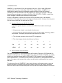
I. INTRODUCTION
GAMEPAC 1 is a collection of four games designed to run on a Sol or other 8080 based
computer with a Processor Technology VDM-1 Video Display Module. GAMEPAC 1 is
distributed on cassette requiring a hardware cassette interface such as the Processor
Technology CUTS circuit board to read the programs into memory for execution. Although
these programs are designed to interface with either SOLOS/CUTER, CONSOL or other user
written surrogate, standard input routines are also provided.
All input to the games is via either the SOLOS/CUTER jump table (refer to the interface
specification in the appendix) or the standard input routines provided. All output from the games
is to the screen--either the Sol display or the VDM-1.
A. Hardware Requirements for All of the Games
1. All of the games require no more than 4K of RAM from location zero through
0FFFH.
2. All games are entered or re-entered at location zero.
3. All games require either the Sol display circuitry or a Processor Technology VDM-1
circuit board. The display scroll port must be either 0FEH or 0C8H.
4. The character generator chip number 6574 is suggested.
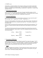
5. The video display switches should be set as follows:
1
2
3
4
5
6
Sol
off
off
off
on
off
on
VDM-1
off
on
on
on
on
off
B. CUTS Cassette Tape Information
The games of GAMEPAC 1 are recorded using the Processor Technology CUTS/Kansas City
standard recording format. The tape is loaded using a Sol with SOLOS or CONSOL personality
module or a computer running under CUTER and a CUTS (Computer Users Tape Standard)
audio cassette board. The SOLOS/CUTER interface specifications in the appendix describe the
format of the tape so that a user written routine may be used to read the games into memory
from tape.
To load a game from the GAMEPAC 1 tape, rewind the tape, set the tape counter to zero and
advance the tape to just ahead of the counter indication number for the game to be loaded.
Make sure the tone and volume are adjusted correctly and the necessary cables are connected.
1
©1977 Software Technology Corporation
I. INTRODUCTION (cont.)
The following examples show the SOLOS/CUTER commands used to load and execute the
games.
XEQ (name)cr
Where:
XEQ
is a SOLOS/CUTER command which causes
the next (or named) program to be read from
tape into memory.
(name) is the name of the program to be loaded. (name)
is optional, and the next program on the tape
will be loaded if it is not used.
cr
This is the carriage return key.
The game, which is a program, will be loaded into memory and run at location zero. It will then
display any necessary instructions on the screen.
For example:
XEQ TARG
XEQ LIFE
XEQ PTRN
XEQ ZING
to play TARGET
to play LIFE
to play PATTERN
to play ZING
"GET (name)cr" may also he used to load the tape.
After the program loads and the prompt character reappears on the screen, type "EX 0cr" to
execute the program.
If you have any trouble loading the tape, refer to the cassette operating procedures in the Sol
manual or the CUTS manual.
2
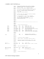
II. GAMEPAC 1 INPUT ROUTINES
All of the games use the same standard input routines from location 0-26.
The first time a game is executed, this input routine will be initialized. A description of this input
routine and the initialization procedures follow. If the games are used with either
SOLOS/CUTER, CONSOL or a compatible surrogate, no modification will be necessary.
A standard input routine will be selected automatically in the event that none of the above
routines are used.
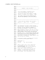
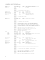
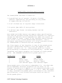
An assembly listing of the standard input and initialization routines is on the following pages.
3
©1977 Software Technology Corporation
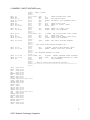
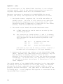
II. GAMEPAC 1 INPUT ROUTINES (cont.)
0001
0002
0003
0004
0005
0006
0007
0008
0009
0010
0011
0012
0013
0014
0015
0016
0017
0018
0019
0020
0021
0022
0023
0024
0025
0026
0027
0028
0029
0030
0031
0032
0033
0034
0035
0036
0037
0038
0039
0040
0041
0042
0041
0044
0045
0046
0047
0048
0049
0050
0051
0052
0055
0054
0055
0056
0057
0058
0059
0060
0061
0062
0063
0064
0065
0066
0067
4
*
**************************************************
*
*
*
< GAMEPAC 1 INPUT ROUTINES >
*
*
*
**************************************************
*
*
*
ALL OF THE GAMEPAC 1 PROGRAMS USE THE
*
SOLOS/CUTER/STANDARD INPUT ROUTINE.
*
*
THE ROUTINE SOURCE CODE/ASSEMBLY IS SHOWN
*
BELOW AS IT APPEARS IN ALL GAMEPAC 1 GAMES.
*
*
THE 'START' VALUE IN EACH PROGRAM WILL BE
*
THE STARTING ADDRESS OF THE ACTUAL GAME,
*
AND WILL BE UNDEFINED IN THE LISTING BELOW.
*
*
*
**************************************************
*
*
* < SOLOS/CUTER AND STANDARD INPUT ROUTINES >
*
*
*
* VERSION 2.4
APRIL 1,1977
S. DOMPIER
*
*
*
**************************************************
*
*
* THIS PROGRAM MAY USE ONE OF THREE POSSIBLE
* INPUT ROUTINES. ON ENTRY TO THIS INITIALIZING
* ROUTINE, THE FIRST TWO BYTES POINTED TO BY
* REGISTERS HL ARE CHECKED TO DETERMINE IF
* THE EXECUTING PROGRAM IS 'SOLOS' OR 'CUTER'.
*
* WHEN A PROGRAM IS CALLED BY THE 'XEQ' OR 'EXEC'
* COMMAND FROM SOLOS/CUTER, REG HL IS SET TO THE
* FIRST ADDRESS OF SOLOS/CUTER. THE FIRST TWO
* BYTES OF SOLOS = 00 C3; THE FIRST TWO BYTES
* OF CUTER = 7F C3. IF THE DATA IN THE FIRST TWO
* BYTES POINTED TO BE REG HL MATCHES, AND THE LDA
* INSTRUCTION (3AH) AT SOLOS/CUTER ADDRESS xx1FH
* ALSO MATCHES THE INPUT ROUTINE ADDRESS OF
* SOLOS/CUTER IS INSERTED AT 'INADD' WHICH IS THE
* INPUT ROUTINE CALL ADDRESS.
*
*
* IF NO MATCH IS MADE, A STANDARD INPUT ROUTINE
* IS USED WITH THE FOLLOWING VALUES:
*
*
* STATUS PORT = 0
* DATA PORT
= 1
* DAV MASK
= 40H DATA AVAILABLE
*
*
*
* THERE IS ROOM TO ADD A 'CMA' INSTRUCTION
* TO COMPLEMENT THE INPUT STATUS WORD FOR
* ACTIVE LOW STATUS.
* (SEE THE STANDARD INPUT ROUTINE BELOW FOR
* ACTUAL VALUE ADDRESS INFORMATION.)
*
* TYPING 'ESC' (escape) WILL EXIT THE MAIN
* PROGRAM. IF SOLOS/CUTER HAS CALLED, A
* JUMP BACK TO SOLOS/CUTER 'RETRN' (xx04H)
* WILL BE MADE. THIS JUMP RETURNS TO THE
II. GAMEPAC 1 INPUT ROUTINES (cont.)
007E
001B
00C3
00CD
0004
0000
007F
003A
001F
0000
0000 C3
0001 27 00
0003 CD OA 00
0006 CA 03 00
0009 C9
0068
0069
0070
0071
0072
0073
0074
0075
0076
0077
0078
0079
0080
0081
0082
0083
0084
0085
0086
0087
0088
0089
0090
0091
0092
0093
0094
0095
0096
0097
0098
0099
0100
0101
0102
0103
0104
0105
0106
0107
0108
0109
0110
0111
0112
0113
0114
0115
0116
0117
0118
0119
0120
0121
0122
0123
0124
0125
0126
0127
0128
0129
0130
0131
0132
0133
0134
0135
0136
0137
* SOLOS/CUTER MONITOR AND ISSUES A PROMPT.
* OTHERWISE THE DEFAULT RETURN JUMP ADDRESS
* WILL BE TAKEN. IT IS INITIALLY SET TO
* RETURN TO THE 'ALS8', ADDRESS 0E060H
*
* IF YOU ARE USING THE STANDARD INPUT ROUTINE
* AND WISH TO INSERT YOUR OWN EXIT ADDRESS,
* DO SO AT 'EXADD' ADDRESS 001AH-001BH.
* LSB - MSB
* (SEE EXIT ROUTINE BELOW.)
*
*
* TYPING 'DEL' WILL RESTART THE MAIN PROGRAM
* AT ITS STARTING ADDRESS
*
* A JUMP ADDRESS TO THE ACTUAL PROGRAM
* IS INSERTED AT 'IJMP' AT THE COMPLETION
* OF THIS INPUT INITILIAZION.
* THIS ALLOWS RESTARTING THE GAME FROM
* LOCATION ZERO (00).
*
*
*
*
**************************************************
*
*
*
* < INPUT ROUTINE EQUATES >
*
DEL
EQU
7FH
DELETE KEY CODE
ESC
EQU
1BH
ESCAPE KEY CODE
JMP
EQU
0C3H
JUMP INSTRUCTION CODE
CALL
EQU
0CDH
CALL INSTRUCTION CODE
RETRN EQU
4
SOLOS/CUTER RETURN LOW ADDRESS
NOP
EQU
0
SOLOS FIRST BYTE
MOVAA EQU
7FH
CUTER FIRST BYTE
LDA
EQU
03AH
SOLOS/CUTER INPUT FIRST BYTE
LOWIN EQU
1FH
SOLOS/CUTER INPUT LOW ADDRESS
*
*
*
XEQ
0
PROGRAM EXECUTE ADDRESS
ORG
0
ASSEMBLER ORIGINATE ADDRESS
*
*
*
* < INITIALIZE INPUT ADDRESS >
*
*
IJMP = INIT2 - INITIALIZE INPUT ON PASS 1.
*
*
AFTER THE INITIALIZATION PASS, IJMP = THE
*
STARTING ADDRESS OF THE PROGRAM TO BE RUN.
*
*
INIT
DB
JMP
START JUMP
IJMP
DW
INIT2 PASS 1= INIT2 PASS 2= START
*
*
*
* < WAIT FOR KEYBOARD INPUT >
*
INWAIT CALL
INCHR CHECK IF INPUT
JZ
INWAIT FOR INPUT
RET
.
WITH CHARACTER IN REG A
*
*
*
* < INPUT ROUTINE CALL >
*
5
©1977 Software Technology Corporation
II. GAMEPAC 1 INPUT ROUTINES (cont.)
000A CD
000B 1C 00
0OOD C8
000E
0010
0013
0015
0018
FE
CA
FE
CA
C9
1B
19 00
7F
00 00
0019 C3
001A 60 FO
0000
0001
0040
007E
E060
001C DB 00
001E 00
001E
0021
0022
0024
0026
6
E6 40
C8
DB 01
E6 7F
C9
U
0138
0139
0140
0141
0142
0143
0144
0145
0146
0147
0148
0149
0150
0151
0152
0153
0154
0155
0156
0157
0158
0159
0160
0161
0162
0163
0164
0165
0166
0167
0168
0169
0170
0171
0172
0173
0174
0175
0176
0177
0178
0179
0180
0181
0182
0183
0184
0185
0186
0187
0188
0189
0190
0191
0192
0193
0194
0195
0196
0197
0198
0199
0200
0201
0202
0203
0204
0205
0206
0207
INCHR
INADD
DB
DW
RZ
CALL
INPUT
.
FIRST BYTE OF CALL INSTRUCTION
INPUT ROUTINE ADDRESS
NO INPUT
*
*
*
* < EXIT/RESTART CODE CHECK >
*
RTEST CPI
ESC
ESCAPE KEY?
JZ
EXIT
CPI
DEL
DELETE KEY?
JZ
START START PROGRAM OVER
RET
.
CHARACTER IN REG A
*
*
*
* < PROGRAM EXIT JUMP >
*
EXIT
DB
JMP
EXADD DW
FORMS PROGRAM EXIT ADDRESS
*
*
*
* < STANDARD INPUT ROUTINE >
*
* THIS ROUTINE IS USED IF THE CALLING PROGRAM
* IS NOT SOLOS OR CUTER. THE DAV MASK AND PORTS
* MAY BF CHANGED AS REQUIRED FOR ANY INPUT VALUES.
* IF INPUT STATUS IS ACTIVE LOW, INSERT THE 'CMA'
* (2FH) INSTRUCTION AT THE 'NOP' ADDRESS 001EH BELOW
*
*
* ZERO FLAG IS SET IF NO INPUT RCV'D. (Z)
* ZERO FLAG IS RESET IF INPUT IS RCV'D. (NZ)
* CHARACTER IS RETURNED IN REG A.
*
* REGISTERS MODIFIED: A
*
STAT
EQU
0
STATUS PORT
DATA
EQU
1
DATA PORT
DAV
EQU
40H
DATA AVAILABLE MASK- ACTIVE HIGH
PARITY EQU
7FH
PARITY MASK
FORMS EQU
0E060H EXIT ADDRESS
*
*
*
INPUT IN
STAT
STATUS PORT = O
*
NOP
.
INSERT 'CMA' (2FH) HERE
*
FOR ACTIVE LOW STATUS
*
ANI
DAV
DATA AVAILABLE MASK = 40H
RZ
.
NO INPUT
INDATA IN
DATA
DATA PORT = 1
ANI
PARITY STRIP PARITY
RET
.
WITH CHARACTER IN REG A
*
*
*
**************************************************
*
*
*
* < INITIALIZE INPUT ADDRESS (SOLOS/CUTER) >
*
* THIS CODE CAN GO ANYWHERE; IT IS USED
* ONLY ONCE AND MAY BE OVERLAYED AFTER
* THE INPUT IS INITIALIZED.
*
* NOTE: TO FORCE STANDARD INPUT ROUTINE,
II. GAMEPAC 1 INPUT ROUTINES (cont.)
0027
0028
0029
002B
002E
002E
0030
0032
23
7E
FE
C2
2B
7E
FE
CA
C3
4A 00
00
3A 00
0035 FE 7F
0037 C2 4A 00
003A
003C
003D
003E
2E 1F
7E
FE 3A
C2 4A 00
0042 22 0B 00
0045 2E 04
0047 22 1A 00
004A 21 00 00
004D 22 01 00
0050 E9
CALL
DATA
DAV
DEL
EORMS
ESC
EXADD
EXIT
IDONE
IJMP
INADD
INCHR
INDAT
INIT
INIT2
INPUT
INWAI
JMP
LDA
LOWIN
MOVAA
NOP
PARIT
RETRN
RTEST
SETUP
STAT
00CD
0001
0040
007F
E060
001B
001A
0019
004A
0001
000B
000A
0022
0000
0027
001C
0003
00C3
003A
001F
007E
0000
007F
0004
000E
003A
0000
U
0208
0209
0210
0211
0212
0213
0214
0215
0216
0217
0218
0219
0220
0221
0222
0223
0224
0225
0226
0227
0228
0229
0230
0231
0232
0233
0234
0235
0236
0237
0238
0239
0239
0241
0242
0243
0244
0245
0246
0247
* EXEC 'IDONE'
*
*
INIT2 INX
H
CHECK SECOND BYTE (JMP)
MOV
A,M
CPI
JMP
JMP INSTRUCTION?
JNZ
IDONE NO MATCH, USE STANDARD INPUT
DCX
H
MOV
A,M
CHECK FIRST BYTE
CPI
NOP
CHECK IF SOLOS: =ZERO
JZ
SETUP YES
*
CPI
MOVAA CHECK IF CUTER: =7FH
JNZ
IDONE NOPE, USE STANDARD
*
*
SETUP MVI
L,LOWIN SET SOLOS/CUTER INPUT >ADDR
MOV
A,M
CHECK FOR 3AH
CPI
LDA
SOLOS/CUTER INPUT FIRST BYTE
JNZ
IDONE NOPE, USE STANDARD
*
SHLD
INADD SET INPUT ROUTINE ADDRESS
*
*
*
SET SOLOS/CUTER RETURN ADDRESS 023'
*
MVI
L,RETRN SOLOS/CUTER RETURN (xx04)
SHLD
EXADD INSERT INTO EXIT ROUTINE
*
*
* SET PROGRAM ADDRESS AT IJMP.
*
IDONE LXI
H,START INSERT PROGRAM START ADDRESS
SHLD
IJMP
SET UP PROGRAM RESTART AT ZERO
PCHL
.
GOTO PROGRAM
*
*
* < END OF INPUT INITIALIAZION ROUTINE >
**************************************************
*
0138
0191
0189
0148
0157
0146
0235
0147
0214 0221 0227
0241
0229
0130
0124
0139
0131
0123 0156 0213
0226
0224
0220
0217
0192
0234
0218
0184
7
©1977 Software Technology Corporation
III. TARGET
(TARG)
(Version 2.4 January 7, 1977 S. Dompier)
TARGET is an animated Sol-VDM game with sound.
A. Mission
A movable photon missile is aimed and fired in an attempt to stop unmanned runaway
robot spaceships.
There are several types of spaceships containing dangerous cargoes of pesticides, DNA
experiments, artificial flavorings, TV commercials and so on. They should be stopped
before they reach a civilized area of the universe and endanger the populace.
Remote control of the missiles in flight is achieved by aiming the launching tube. The
ships (and their contents) are generated by random logic and follow no pattern.
If two ships should collide, the flight log as well as the most dangerous cargo on board
are jettisoned as a mass-seeking ion parachute which must be considered the most
dangerous hazard of all.
[Author's note: The game player may relate to the ships and missiles of TARGET
as objects personally imagined by him. The above scenario is
provided for those with an aversion to the destructive type games
who may otherwise mistake the robot spaceships as earthly in
origin. Aggression, still being a common human trait in 1977, is
better exercised with a zero-sum game than spent on the physical
real world. Besides--it's fun.]
B. Scoring
HITS:
BIG CARGO SHIPS
100 points
SMALL (& fast) SCOUT SHIPS
200 points
PARACHUTES
600 points (if you can hit them!)
Chain reaction multiple hits score extra!
MISSES:
8
ANY SHIP ESCAPING OFF-SCREEN
-20 points
MISSILE MISSES (or wasted by hitting explosion)
-30 points
III. TARGET (cont.)
Occasionally, an explosion will blow out the engines or destroy part of another nearby ship or
parachute, leaving parts of it floating in space. This space debris will remain until it is hit by a
missile or by another ship, the crash resulting in the generation of a parachute. A missile hitting
the debris will score.
C. Game Start and Action Speed
After the instructions are displayed on the screen, the game is started by typing one of the
numeric keys (1 - 9). This also determines the speed of play. The number keys may be used at
any time to change the action speed with 1 designating the fastest action.
D. Aiming and Flight Direction
Missile aiming and in-flight direction are controlled by pressing the "," key to aim left and the "."
key to aim right. (The "," keytop has a "<" and the "." keytop has a ">".)
There are five aiming positions: left, left-center, center, right-center and right. The missiles are
launched by typing any letter key or depressing the space bar. This keyboard arrangement is
the easiest to use.
As soon as the first missile has left the launching tube, another missile may be launched. The
directions of missiles already launched will be altered by the aiming position of the launching
tube.
The left and right aiming command keys may be changed if your keyboard layout makes the
standard keys undesirable. Place the ASCI I code (7 bits, MSB parity should be 0) for the keys
to be used as follows:
Left key:
Address 0600H
Currently 2CH (,)
060DH
Right key:
Address 0607H
Currently 2EH (.)
061CH
E. Demonstration (DEMO) Mode
A demonstration self-run mode may be initiated by typing "D" at the start of the game. The "D"
takes the place of a speed key (1 -9) to start the game. The game will run itself until stopped by
typing the "DEL" key. All aiming, launching and speed controls are enabled during the demo
mode, allowing for manual operation as the system "helps" the operator along!
F. Sound
TARGET is equipped with sound-effects. Place any AM radio near the computer and run the
demo mode. Adjust the radio dial and the radio itself in relation to the computer until a good
sound is found. Small ships, big ships, parachutes,
9
©1977 Software Technology Corporation
III. TARGET (cont.)
and especially explosions should all be distinctive. For the best sound from a Sol, place the
radio next to the center of the left side.
G. Game Time
During play, "Time" will flash and a countdown will appear at the top of the screen when eight
seconds of play time remain. If the score is 4000 or greater, "extra time" goes into effect, and
20 extra seconds of play time are provided.
When the game is over, (TIME = 0), the instructions will be displayed on the screen and the
score information will remain until a new game is started by typing one of the speed keys (1 - 9).
If the current score is greater than the previous high score, it will become the "NEW HIGH
SCORE". The high score may be cleared by typing "R" before starting a new game.
H. Extra Time
The thousands digit in the score is used to determine whether "extra time" is to be initiated.
This value may be altered to any digit (1 - 9) by placing the ASCII value of the desired digit at
location D02H in memory. For example, if 2000 is to be used as the minimum score to earn
extra time, place 32Hex at location D02H in memory.
I.
Other Commands
If the "DEL" (delete - 7FH) is typed at any time, the game will restart.
There are two commands which are not displayed on the screen. One is a super slow speed
activated by typing "%" (shift-5). To resume normal speeds, type any numeric key.
The other command is a continuous run mode which is activated by typing Control-C (03H)
either before or during the game action. The game will then run continuously until stopped by
typing the "DEL" key.
J. Exit from TARGET program
An exit from TARGET is provided by typing "ESC" (1BH), ("ALT" on some keyboards). See the
standard SOLOS/CUTER input routine for complete information.
10
IV. LIFE
(LIFE)
(version 2.3 January 7, 1977 S. Dompier)
The game of LIFE was originally described in SCIENTIFIC AMERICAN magazine, October,
1970, in an article by Martin Gardner. The game was originated by John Conway of Cambridge
University, England.
The computerized version of LIFE can be found on many computer systems--in many cases
with Teletype print routines. This version, using the Sol computer's video display capabilities or
the VDM-1 Video Display Module with other computers, allows initial patterns to be composed
directly on-screen and instant visualization of each generation as it is created. In addition,
patterns may be stored and recalled from seven memory pattern registers. The generation
speed may be controlled from the console.
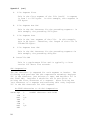
A. Genetic Rules
Cells (organisms, ducks, people, plants, etc.) reproduce, exist or die according to certain
genetic laws. Conway derived the genetic law of the game of LIFE from the following
criteria:
1. There should be no initial patterns for which there is a simple proof
that the population can grow without limit.
2. There should be initial patterns that apparently do grow without limit.
3. There should be simple initial patterns that grow and change for a
considerable period of time before coming to an end in one of three
possible ways:
a. fading away completely (no life)
b. becoming stable (no change in pattern or population)
c. a pattern oscillates in an endless cycle of two or more
periods.
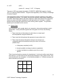
Think of each cell as being a square of a checkerboard. A celI may be either empty (shown
as a space [no *] on the screen and in the following examples) or living (shown as an * both
on the screen and in the examples). In the following examples, a '+' indicates an empty cell
which is becoming a living cell.
1
2
3
4
*
5
6
7
8
11
©1977 Software Technology Corporation
IV. LIFE (cont.)
SURVIVALS
Each live cell with TWO or THREE live neighbors
will survive for the next generation.
*
* *
DEATHS
*
* * *
These cells
all survive.
Each cell with FOUR or MORE live neighbors will die from
over-population.
*
* * - This cell dies (4 neighbors)
* *
Each cell with ONE or NO live neighbors will die from
isolation.
Both of these cells die from isolation,
each having only one neighbor.
*
*
BIRTHS
Each empty cell with EXACTLY THREE live neighbors is a
birth cell and a new live cell will appear at the next generation.
*
*
+
* = birth - three neighbors
Note: Births and deaths occur simultaneously.
Don't count a new cell until next generation.
Generation 1
Generation 2
+
* * *
=
x
*
+
x
=
*
(+ = birth - had three neighbors)
*
(x = death - only one neighbor)
*
B. Operating Instructions
In this version of LIFE you have a choice of either a flat world or a round world display.
FLAT WORLD - Cells on the edge of the display do not have neighbors past the edge, and
any births that occur there immediately fall off and are not counted. In
computing the count of neighbors, cells past the edge are considered
empty. This is similar to a petri dish.
ROUND WORLD - Presented here as a flat surface projection, cells on the edge of the
display have neighbors at the opposite edge of the display (top-bottom;
left-right). If a pattern is moving off the edge of the display, it will continue
at the opposite side.
12
IV. LIFE (cont.)
The round world representation is more representative of our Earth, and it
usually yields more interesting pattern activity.
C. Pattern Storage
A pattern may be stored and recalled from seven memory pattern registers. When the question
is asked, type the appropriate register number (1 - 7) to recall a previous pattern. The pattern
stored in that register will be copied to the screen. The pattern may then be 'activated' by typing
a speed key (1 - 9 and 0) or modified by the edit functions and then run.
When the question is asked, type the register number (1 - 7) in which to save an initial or
modified pattern. The pattern will be saved after the numeric (speed) key is typed. (Note: If you
type 'DEL' to start over before the pattern has been run, no register storage will occur.)
There are seven preset patterns in register storage. When the LIFE program is first loaded from
tape, get and run these patterns in both the round and flat world modes. This provides
familiarity as well as examples of some of the possible LIFE activities.
D. Generation Speed
The time between each generation may be controlled by typing a speed key (1 - 9 and 0). 1 is
the fastest and 9 is the slowest. Typing '0' (zero) will stop the generation activity to allow
extended study of a pattern.
The pattern may then be SINGLE STEPPED by typing the space bar. Typing a speed key will
resume automatic generations.
Typing the 'DEL' key will restart the LIFE program.
Typing the 'ESC' key will exit from the program.
13
©1977 Software Technology Corporation
V. PATTERN
(PTRN)
PATTERN is a pattern generating program for use with the Sol computer or a computer with a
VDM-1 Video Display Module. The patterns are generated in a kaleidoscopic format using a
horizontal and a vertical value as the initial input data.
The pattern may be selected from a possible list of 256 different patterns. Each combination of
vertical and horizontal values will produce a unique pattern. There is also an automatic pattern
mode which generates a sequence of some of the more interesting patterns.
The initial speed of PATTERN change is selected by typing any key. This key also starts the
program. The binary value of the key used to start the pattern is used as a timer; the lower the
value the faster the rate of change. The ASCII bias (30H) is removed from the speed key used,
and the resulting value is decremented by 1. Therefore, the fastest speed would be selected by
typing the number "1". The space bar produces a very slow rate of change. The number keys
(1 - 9) produce a good range of speeds, with the number "9" being quite slow.
The program may be restarted by typing the "DEL" key, or by restarting the program at location
zero. Typing the "ESC" key will exit from the PATTERN program.
A. Loading PATTERN from CUTS Tape
Set the GAMEPAC 1 tape so that PTRN is the next program on the tape, and read the tape
using the XEQ command, i.e., XEQ PTRN or just XEQ.
PATTERN will then load and run, printing instructions on the screen. The hexadecimal value of
the numbers typed for the pattern data is represented as an eight bit word on the screen and is
a good way to become familiar with the hex numbering system:
(0,1,2,3,4,5,6,7,8,9,A,B,C,D,E,F).
14
VI. ZING
(ZING)
Written by: Terry L. Todd May 1976
Revised by: Steven Dompier June 3, 1976
Revised for SOLOS/CUTER/STANDARD July 5, 1977
ZING is a ping-pong type game played using a Processor Technology VDM-1 Video Display
Module or a Sol computer.
When using ZING with a Sol, a switch bank must be constructed in order to play the game.
Details and a schematic are provided in the following pages.
If the computer is other than a Sol, a switch bank may be constructed incorporating a parallel
port; however, the normal mode of play will use the front panel sense switches.
A. ZING Operation
Two paddles move up and down the screen sides and return any ball that hits them. Balls
are generated at random from the center of the screen, and up to five balls may be in play at
any one time. If all five balls have been returned, the balls will move faster. The balls will
gain momentum each time all five balls are returned until a maximum speed is attained. As
soon as any ball is missed, the initial slower speed is restored.
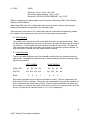
B. Paddle Operation
The left four sense switches control the left paddle, and the right four switches control the
right paddle. The paddles are positioned up or down according to the binary setting of each
player's four switches.
LEFT PADDLE
DATA LINE:
SWITCH:
ROW:
D7
D4
:
A15 A14 A13 A12
:
8
D6
4
D5
RIGHT PADDLE
2
1
:
D3
D2
D1
D0
A11 A10
A9
A8
2
1
8
4
Row (above) specifies the row at which the Paddle is located. The row is selected by the
binary value of all four switches. The top row (0) is accessed by turning all four switches off.
Row 1 would require a switch setting of 0001. Row 3 would have both the one switch and
the two switch on, giving a total value of three (0011), and so on, counting in binary, until the
last row (15) has all four switches turned on: 1111 or F hexadecimal).
15
©1977 Software Technology Corporation
VI. ZING (cont.)
C. Game Start
The switch settings at the start of the game are used to determine two modes of play. If the
left player's "8" switch is on when the game starts, hexadecimal row numbering will be
displayed at the sides of the screen. If the right player's "1" switch is on at the beginning,
the game will run continuously until stopped by pushing the 'DEL' key to restart the game. If
the right player's "1" switch is off at the start, the game will declare a winner when either
player scores 21 points. The game may then be restarted by pushing the 'DEL' key.
SWITCH A15 up
=
Display hex numbering on screen side
SWITCH A15 down
=
No numbers
SWITCH A8 up
=
Continuous game - No stop at 21
SWITCH A8 down
=
Winner at 21
The momentum of the game increases each time both players have returned all five balls
with no misses!
Run and restart game at location zero.
Type 'DEL' to restart game anytime.
Type 'ESC' to exit from the program.
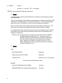
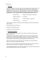
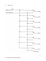
D. Sol Parallel Port Switches
A bank of eight switches (or two bank's of four switches--one bank for each player) are
required to play ZING.
These switches are connected to the parallel port at the rear of the Sol (connector J2M.
Use SPDT type switches without a middle "off" position. Connect the switches using a
DB-25 connector to mate with the parallel port connector J2 on the Sol. Provide enough
connecting wire so that the switches may be positioned conveniently for play.
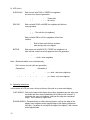
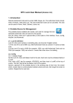
Refer to the Sol manual for the parallel port pin-out information, and see the schematic
(Figure 1) for the correct hook-up of the switches.
If you wish to use external switches with a computer other than a Sol, construct the switch
bank(s) as shown and connect to a parallel port using the lines indicated.
On parallel ports other than the Sol, +5 volts must be obtained to power the switches. Notice
that this is obtained from pin 3 on the Sol J2 connector.
16
VI.
ZING (cont.)
Figure 1
17
©1977 Software Technology Corporation
VI. ZING (cont.)
E. Patches
The GAMEPAC 1 programs use the SOLOS/CUTER or standard input routine and
determine if the computer running the program is a Sol using SOLOS, some other computer
using CUTER, or something else. The information below will allow you to modify the
program for different combinations, such as using external sense switches with the Sol
running SOLOS or some other computer running CUTER and using an external switch
bank.
If the computer is a Sol, the parallel port (FD) is used for the switch bank input. If the
computer is not a Sol running SOLOS, the sense switch port (FF) is used. To change this
input port, first run the program to initialize the input routines, then stop the computer and
make the patches needed, then restart ZING at location zero. The new port address wiII
then be used.
The switch bank input port used is loaded from address 0027H. Change this byte if
necessary.
18
APPENDIX A
SOLOS/CUTER Interface Specifications
The SOLOS/CUTER interface is based on:
1. A predefined set of 'pseudo' I/O ports allowing
software compatibility and providing an easy means
of supporting any I/O device.
2. A well defined set of register usage conventions.
3. A system jump table of entry points.
4. A defined tape format including headers and CRC
characters.
Both SOLOS and CUTER observe and support these specifications
such that any program written using this interface will function
(except for specific device dependencies) under the control of
either SOLOS or CUTER. A part of the interface specifications
also allows a user written SOLOS/CUTER surrogate. Such a
surrogate, when properly written, will allow a program written
for SOLOS/CUTER to function with the surrogate.
The first aspect of the interface is that of the pseudo ports.
The basic SOLOS/CUTER interface allows the support of four
'pseudo' I/O ports (0 - 3). These pseudo ports are logical
ports providing a reference for the program only. System input
(keyboard) and output (display) are directed via these pseudo
ports. The STANDARD definition for pseudo ports is:
Pseudo Port
0
1
2
3
Input
Keyboard
Serial input
Parallel input
User defined input
Output
VDM Display
Serial output
Parallel output
User defined output
These pseudo ports allow device independent I/O. Provided that
device dependent character sequences are not used, an I/O
request to pseudo port 0 appears to the requesting program to be
the same as a request to pseudo port 1, 2 or 3. What this means
is that, although four pseudo ports are defined in the interface
specifications, a user written surrogate would not need to
decode pseudo ports.
19
©1977 Software Technology Corporation
Appendix A
(cont.)
The second aspect of the SOLOS/CUTER interface is the defined
register usage. Each of the system entry points has specific
register requirements which will be discussed later.
Whenever a program is executed via SOLOS/COTTER the stack
pointer, the stack, and registers HL are defined as follows:
1. The Stack Pointer (register SP) is valid and offers a
useable stack. The size of this stack is not specified
but should be adequate for at least a few calls. The
executed program is expected to establish its own stack;
however, some stack should be available.
2. The stack itself should be established such that:
(a)
A "REV instruction can be used as an exit by the
executing program.
(b)
The locations at Stack Pointer -1 and -2 in memory
contain the address of the executed program itself.
This information can be accessed by machine code
similar to:
LXI
DAD
MOV
H,-1
SP
A,M
A constant minus one.
HL=SP-1 now.
A=our own high address.
Code such as this can be used to allow a routine to
be made self-relocating to a 256 byte boundary.
3. Registers HL contain the address of the SOLOS/CUTER jump
table. Because this jump table may be located at any 256
byte boundary in memory, register L will be zero.
Register H can then be used to alter the executing program
accordingly. As noted later, the jump table also provides
an indication whether the program is executing on a Sol or
other computer.
The third aspect of the SOLOS/CUTER interface is the jump table.
By making all system requests via this jump table, an executed
program can be made compatible between SOLOS, CUTER or other
properly written surrogate. The jump table is described on the
following page. A more complete description is contained in the
SOLOS/CUTER User's Manual.
20
Appendix A (cont.)
SOLOS/CUTER JUMP TABLE
Address
Label
Length
Brief Description
xx00
START
1
This byte allows power-on reset for
SOLOS. It is 00 hex on a Sol; 7F hex
on other than a Sol.
xx01
xx04
INIT
RETRN
3
3
This is a "JMP" to the power-on reset.
Enter at this point to return control
from an executing program.
xx07
FOPEN
3
Byte access file open.
xx0A
FCLOS
3
Byte access file close.
xx0D
RDBYT
3
Byte access read one byte.
xx10
WRBYT
3
Byte access write one byte.
xx13
RDBLK
3
Read an entire file into memory.
xx16
WRBLK
3
Write an entire file from memory.
xx19
SOUT
3
Standard character output routine. This
must be an "LDA" pointing to the byte
containing the current system output
pseudo port value.
xx1C
AOUT
3
Character output to pseudo port specified
in register "A".
xx1F
SINP
3
Standard character input routine. This
must be an "LDA" pointing to the byte
containing the current system input
pseudo port value.
xx22
AINP
3
Character input to pseudo port specified
in register "A".
The most often used routines are: RETRN, SOUT and SINP.
points may or may not be used.
Other entry
21
Appendix A
(cont.)
JUMP TABLE INPUT ENTRY POINTS
SINP
address xx1F
This entry point will set register "A" to the current
system input pseudo port. This must be an "LDA"
instruction. After loading register "A", this entry
point proceeds by executing "AINP" described below.
AINP
address xx22
This entry point is used to input one character or status
information from any pseudo port. On entry register "A"
indicates the desired pseudo port. Because this entry
point is a combination status/get-character routine, it
is the user's responsibility to interpret return flags
properly. When a character is not available, the zero
flag will be set. When a character is available, the
zero flag will be reset and the character will be
returned in the "A" register. As an example, the
following code will wait for a character to be entered:
LOOP CALL
JZ
...
SINP
LOOP
...
get status or the character
status says character not
available yet
character is in register "A"
JUMP TABLE OUTPUT ENTRY POINTS
SOUT
address xx19
This entry point will set register "A" to the current
system output pseudo port. This must be an "LDA"
instruction. After loading register "A", this entry
point proceeds by executing "AOUT" described below.
AOUT
address xx1C
This entry point is used to output the character in the
"B" register to the pseudo port specified by the value in
the "A" register. On return, the PSW and register "A"
are undefined. All other registers are as they were on
entry. A user written output routine (AOUT surrogate)
may buffer or delay the output as required for the
supported device.
22
Appendix A
(cont.)
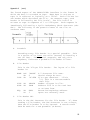
The fourth aspect of the SOLOS/CUTER interface is the format in
which the data is recorded on tape. When data is written to
tape it is referred to logically as a "file". Each file has its
own header which describes the file. On cassette tape, each
header is followed by the file itself. The file itself is
written to tape in segments of 1 to 256 bytes. Each segment is
immediately followed by a Cyclic Redundancy Check character (the
CRC). The following is the general format of one file on
cassette tape:
Where:
A.
Preamble
Preceding every file header is a special preamble. This
is a series of at least ten nulls (zeroes) followed by a
one (01 hex). This special sequence, and only this
sequence, indicates a probable file header follows.
B.
File Header
This is the 16 byte file header.
header is:
NAME
C.
TYPE
ASC
DB
DB
'ABCDE'
0
'B'+80H
SIZE
ADDR
DW
DW
LENGTH
FROM
XEQ
DW
DS
EXEC
3
The layout of a file
A 5 character file name.
Should always be zero.
File type character. If bit
7=1, this is a non-executable
data file.
Number of bytes in file.
Address file is to be read into
or written from.
Execution beginning address.
Space not currently used.
File Header CRC
This is the CRC character for the file header. If, when
reading a file header, the CRC character is not correct,
then the file header is to be ignored. A search would
then be made for a new preamble (A above).
23
Appendix A
D.
(cont.)
File Segment First
This is the first segment of the file itself. A segment
is from 1 to 256 bytes. In this example, this segment is
256 bytes.
E.
File Segment One CRC
This is the CRC character for the preceding segment-- in
this example, the preceding 256 bytes.
F.
File Segment Last
This is the last segment of the file. In this example,
this is 44 bytes. Therefore, the length of this file is
256+44=300 bytes.
G.
File Segment Last CRC
This is the CRC character for the preceding segment--in
this example, the preceding 44 bytes.
H. Interfile GAP
This is a gap between files and is typically a clear
carrier for about five seconds.
CRC Computation
The CRC character is computed for each segment or header. The
following code performs the CRC computation assuming: Register
"A" is the character just written to tape, and Register "C" is
the final CRC. Register C should be set to zero prior to
writing the first character of a segment. After writing the
last character of a segment and executing this code, Register
"C" is the CRC character for this segment.
An 8080 Subroutine to do CRC Computation
DOCRC EQU
SUB
MOV
XRA
CMA
SUB
MOV
RET
24
$
C
C,A
C
C
C,A
A=NEXT character and C=CRC