1
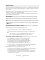
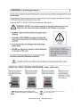
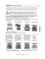
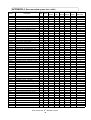
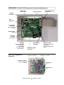
Version 3.0
402s
SE RV I CE & PA RT S M AN UA L
This manual covers UK/EC models manufactured from:
Version 2.0 Serial No. 000745 –001199
Version 3.0 Serial No. 001200 onwards
SERVICE MANUAL
Merrychef
CAUTION MICROWAVE EMISSIONS
DO NOT BECOME EXPOSED TO EMISSIONS FROM THE MICROWAVE
GENERATOR OR PARTS CONDUCTING MICROWAVE ENERGY
402s Ovens Part. No. 32Z3539 Issue 5
1
TABLE OF CONTENTS
Safety code..............................................................................3
Product specifications..............................................................4
Installation instructions ............................................................5
Main features ...........................................................................6
Main features control panel Version 2.0 ..................................7
Main features control panel Version 3.0 ..................................8
Principal components: RHS.....................................................9
Principal components: LHS ...................................................10
Principal components: Control Box .......................................11
Principal components: Back View .........................................12
Principal components: Power Supply ....................................13
Principal components: Cavity Parts & KFC Accessories ......14
Principal components: External panels & Parts.....................15
Principal components: Electronic control panel assembly.....16
Parts matrix...................................................................... 17-18
Procedure for Power output measurement............................19
Procedures for Principal Component tests ..................... 20-21
Procedure for door interlock adjustment.......................... 22-24
Hot Air Motor and controller............................................. 25-26
Circuit Diagram ................................................................ 27-34
Troubleshooting Guide .................................................... 35-39
Appendix 1: Temperature Sensor resistance data ................40
Appendix 2: MenuKey download procedure V2.0 .................41
MenuKey download procedure V3.0 .................42
Appendix 3: Cool down & Cleaning Procedure ............... 43-45
Appendix 4: Recommended Spares List ...............................46
Appendix 5: PCB connection Points ................................ 47-48
Appendix 6: Firmware revision guide............................... 49-54
Appendix 7: Electrical Installation Guide ...............................55
Merrychef Limited,
Station Road West,
Ash Vale, Aldershot
Hampshire GU12 5XA
United Kingdom
Tel: +44 (0)1252 371000 Fax: +44 (0)1252 371007
Internet address: http://www.merrychef.com
E-mail: [email protected] or [email protected]
402s Ovens Part. No. 32Z3539 Issue 5
2
SAFETY CODE
This manual is designed to assist engineers who have been on a recognised product familiarisation
and training course run by Merrychef. It has been prepared to offer technical guidance for the 402s
range of Ovens.
Please remember that it is wiser not to attempt a service task if you are unsure of being able to
complete it competently, quickly, and above all safely.
To avoid injury to yourself, and to protect the appliance from possible damage, please follow this
Safety Code when servicing these ovens.
Before attempting to repair the oven, check it for microwave emission using a calibrated
emission detector.
Check that the oven is not emitting microwaves, even when supposedly not in operation.
Check that the oven is not operating continuously, whether the display indicates cooking or
not.
Always discharge the HT capacitors before working on the oven using a suitably insulated
10 M Resistor.
When testing the oven with covers off run for short periods of time only or magnetrons will
overheat and the display will show Error condition.
Before removing any covers from the oven, do all of the following.
Switch off the mains supply and remove the plug from the wall socket.
or
If the oven is hard wired, ensure that the power is turned off at the isolator switch.
Note:
The On/Off switch on the oven is not adequate protection against electric
shock, as it does not isolate all of the internal wiring from the mains.
Upon completion of a service the oven, or before reconnecting the appliance to the electrical
supply for testing, check all of the following points:
All internal electrical connections are correct (see wiring diagram).
All wiring insulation is correct and is not touching a sharp edge.
All grounding connections are electrically and mechanically secure.
All door safety interlocks are secure and mechanically sound.
The door operation is smooth, and the arms run freely in the slots.
The door activates all four of the door interlock switches and in the correct order
The temperature sensor is correctly connected to the Power PCB.
Before finishing a service call, recheck the following points:
All of the electronics are functioning correctly and all of the touch pads are working.
Microwave emissions are below permissible limit of 5 mW/cm².
The power output of the oven is checked in accordance with the procedure page.
Oven has correct 50mm (2 inches) air gap all round and 50mm (2 inches) above.
Air flow should not be restricted.
402s Ovens Part. No. 32Z3539 Issue 5
3
PRODUCT SPECIFICATIONS
Serial Number (Rating Plate):
Month 00/ Year 00/ Production number 00000
e.g 01 08 03349 Oven manufactured January, 2008, production number 03349
Model Number:
402S VVV F P C R TT ZZ
Supply
Voltage
Freq.
Hz
Phase/Supply
Control
Type
VVV
F
P
C
Voltage (ac)
208 = 208V
220 = 220-230V
240 = 230-240V
5=
50Hz
Phase Arrangement
A=
L + N + E (30 Amp)
6=
60Hz
B=
L1 + L2 + N + E
K=
Electronic
MenuKey
Version
Example 402S2205BK2GMEU
Model No. EC402s
220V, 50Hz, L1 +L2 +N +Earth supply, MenuKey Revision 1, General Market, EU
Type
Country
/Region
R
TT
ZZ
1
2
3
GM =
General
Market
UK =
United
Kingdom
US =
C=
2 P + Gnd (20 Amps)
USA
EU =
D=
2 P + Gnd (30 Amps)
Power
Requirement
See Rating Label
Power Output
Microwave 100% 1500watts
Convection
3250watts
External
Dimensions
Height
595mm (23.0 inches)
Width
585mm (23.0 inches)
Depth
700mm (27.5 inches)
Weight
Nett
90kg ( 198lb.s )
Construction
Cavity
Casework
304 Stainless Steel
402s Ovens Part. No. 32Z3539 Issue 5
4
Europe
INSTALLATION INSTRUCTIONS
Installation Instructions for Mealstream 402s Ovens
Power Supply Requirements
The Mealstream 402s should be connected to a suitable electricity supply, which can cope with
the switching-on surge that occurs with certain types of catering equipment, including
microwaves. Because of this requirement, we strongly recommend that a separate, suitably
rated supply is installed for the oven.
The supply for the oven should be fitted with a Type "C" or Time Delay circuit breaker.
If the oven is hard-wired to the supply, a double-pole isolator switch with a contact gap of at
least 3mm ( 1/8 inch ) should be fitted.
Earth Bond terminal
An Earth Bond Terminal is provided on the rear panel of the oven for independent Earth (GND)
connection.
Grounding requirement
This appliance must be connected to a grounded, metallic, permanent wiring system, or an
equipment grounding conductor should be run with the circuit conductors and connected to the
equipment grounding terminal or lead on the appliance.
Positioning the Oven
In order to maintain adequate ventilation for air intake
and exhaust, and to allow access for cleaning filters,
you must allow a minimum of 50 mm ( 2 inches )
clearance at the sides and rear of the oven.
Air intake temperature should not exceed 45°C (110°F )
excessive temperature will lead to reduced operating duty
cycle, or premature ageing of internal components.
Failure to comply with these conditions will invalidate the
warranty.
NEVER
Install an oven above fryers,
grills, griddles or any other
major heat source.
Note:
The minimum
recommended clearance
required for air flow
ALWAYS Place containers in the cavity
carefully - impact damage
may chip the vitreous enamel
coating on the runners and
baffle plate.
Stacking the oven ( Maximum one only)
Using stacking kit Part No. SA129
402s Ovens Part. No. 32Z3539 Issue 5
5
MAIN FEATURES
m
a
j
b
L
f
g
d
c
e
L
i
h
k
k
a On/Off SWITCH
h DOOR
This is used to turn the oven On or Off.
IT DOES NOT ISOLATE INTERNAL WIRING
FROM THE MAINS SUPPLY.
The door consists of a thermally insulated inner
section, and an additional air gap provided by a
twin skinned door front to lower the surface
temperature.
b MenuKey
i DOOR SEAL
The MenuKey System automatically changes
all the cooking programs with an electronic key
and allows program names to be identified.
These ensure a tight seal around the door.
They should be kept clean and checked
regularly for signs of damage. Replace if worn
or damaged.
c OVEN CAVITY
The oven cavity is mainly constructed from
stainless steel panels. It must be kept clean.
j ELECTRICAL SUPPLY CORD
Electrical supply cord is situated on the rear of
the oven,
d GREASE FILTER
The grease filter must be cleaned on a regular
basis, and kept free of debris.
k AIR FILTERS
Main intake for cooling air for internal
components. Must be clear of obstructions.
e RACK
The cooking rack should be removed daily and
cleaned
L
IMPINGER PLATES ( Upper & Lower)
Direct the air in the cavity. They must be
cleaned on a regular basis, and kept free of
debris
f HOT AIR FAN
Situated behind the grease filter and circulates
the hot air through the cavity.
m STEAM VENT PIPE
g RATING PLATE
Vents steam from the oven cavity
The rating plate is situated on the rear of the
oven, and states the Model, Serial Number,
Electrical Ratings and Manufacturers
telephone number.
402s Ovens Part. No. 32Z3539 Issue 5
6
MAIN FEATURES
Electronic control panel: Version 2.0
FAN SPEED PADS
PREHEAT/ COOL DOWN
PROGRAM
MAIN DISPLAY
PANEL
POWER PADS
TIME/ PROGRAM PADS
CANCEL PAD
Cancels all timed cooking cycles, pre-programmed
operations and stops the microwave energy. It does
not alter the oven temperature. If the oven is hot,
food will continue to cook and should be removed
from the oven immediately. This pad will also cancel
any incorrect operations. It will not erase programs.
FAN SPEED PADS
The Fan speed can be increased and decreased in
5% steps ( 10% to 100% )
FUNCTION PADS
Move through control functions in the Main Display
MAIN DISPLAY PANEL
Shows the principal functions of the oven.
When cooking, the time remaining counts down.
Also displays error messages and oven temperature.
(See TROUBLESHOOTING )
When storing and recalling a program the display
indicates the program number and details
FUNCTION
PADS
START
MenuKey
CANCEL
PAD
MenuKey
The MenuKey System automatically changes all the
cooking programs with an electronic key and allows
program names to be identified.
POWER PADS
The microwave power can be increased or
decreased adjusted in 10% steps. ( 0% to 100% )
The default setting is 50% microwave power.
PREHEAT/ COOL DOWN
Commences main oven heating cycle to a preset
temperature. Press and hold for 5 seconds to
commence cool down procedure ( See CLEANING )
PROGRAM
Activates program mode for storing programs in
memory START PAD Commences a program
TIME/ PROGRAM PADS
These pads are used for setting the cooking time in
1 second steps to a maximum of 10 minutes.
They are also used for storing and recalling
programs from 0-499
Display Panel error messages
Message
Condition
Possible cause
ERROR MAGNETRON 1
Magnetron 1 has overheated
ERROR MAGNETRON 2
Magnetron 2 has overheated
Blocked Air filter(s)
Oven located near hot air sources
Oven being used empty
Cooling fan failure
Magnetron failure
ERROR MAGNETRON 1 & 2
Magnetron 1 and 2 have overheated
CAVITY SENSOR ERROR
Cavity temperature exceeds more
than 50°C above PREHEAT
temperature setting during cook cycle
Indicates combustion ( fire ) in oven cavity
Note: In service operations when
PREHEAT is set to 0°C this message can
appear when the oven is operated
402s Ovens Part. No. 32Z3539 Issue 5
7
MAIN FEATURES
Electronic control panel: Version 3.0
MAIN DISPLAY
PANEL
COOL DOWN
FUNCTION
PADS
FUNCTION
PADS
FUNCTION
PADS
MenuKey
CANCEL
PAD
DISPLAY PANEL
Shows the principal functions of the oven.
When cooking, the time remaining counts down.
Also displays error messages and oven
temperature. When storing and recalling a
program the display indicates the program
number and details.
FUNCTION PADS
The function pads select options shown in the
DISPLAY PANEL.
COOL DOWN PAD
Puts the oven into Cool Down Mode prior to
cleaning
MenuKey 2
The MenuKey System automatically changes all the
cooking programs with an electronic key and allows
program names to be identified
CANCEL PAD
Cancels all timed cooking cycles, pre-programmed
operations and stops the microwave energy. It does
not alter the oven temperature. If the oven is hot, food
will continue to cook and should be removed from the
oven immediately. This pad will also cancel any
incorrect operations. It will not erase programs.
Display Panel error messages
Error Message
Condition
Possible Cause
Magnetron 1 Overheat
Ensure air filters are clean
Allow oven to cool
Magnetron 1 has overheated
Magnetron 2 Overheat
Ensure air filters are clean
Allow oven to cool
Magnetron 2 has overheated
Blocked air filters
Oven located near hot air source
Oven being used empty
Cooling fan failure
Magnetron failure
Magnetron 1 & 2 Overheat
Ensure air filters are clean
Allow oven to cool
Magnetron 1 & 2 have overheated
Magnetron 1 Failure
Magnetron 1 no microwave output
Magnetron 2 Failure
Magnetron 2 no microwave output
Magnetron 1 & 2 Failure
Magnetron 1 & 2 no microwave
output
Ambient Overheat
Ensure air filters are clean
Allow oven to cool
Temperature inside casing has
exceeded limit
Blocked air filters
Restricted airflow to air filters
Oven located near hot air source
Circulation fan failure
Combustion (fire) in cavity
Cavity Overheat
Please contact service
Cavity temperature has exceeded
more than 295°C
Blocked air filters
Restricted airflow to air filters
Combustion (fire) in cavity
Heater Failure
Cavity has not reached a
temperature of 100°C in 10 minutes
One or more heater elements have failed
and need to be replaced
Check power supply
Magnetron failure
402s Ovens Part. No. 32Z3539 Issue 5
8
PRINCIPAL COMPONENTS: Right Side
1
5
6
6
7
2
8
3
26A
71
26
4
70
No.
Description
Part No.
1
Cavity Overheat stat
30Z1024
2
Motor Start Capacitor 2µF ( Blue )
30Z1298
3
Filter 16A (Threaded)
30Z1340
4
SA276
5
SA288
6
Microswitch SW1
7
Door Hinge Assembly RH
8
Magnetron Cooling Fan
30Z1295
26
HV Capacitor 2500V 1.1µF ( 50HZ models )
30Z1242
HV Capacitor universal clip
31Z1261
70
Fibre Optic PCB
11M0364
71
Solid State Relay
30Z1362
26A
30Z1294
402s Ovens Part. No. 32Z3539 Issue 5
9
PRINCIPAL COMPONENTS: Left Side
5
24
6
6
9
3
25A
10
25
70
4
No.
Description
Part No.
3
Filter 16A (Threaded)
4
Air filter
SA276
5
Stirrer motor Assembly
SA288
6
Microswitch SW3
30Z1340
30Z1294
Microswitch SW4
9
Door Hinge Assembly LH
10
Motor Controller
30Z1319
24
Thermistor Cavity
30Z1315
25
HV Capacitor 2500V 1.0µF ( 50Hz models )
30Z1331
25A
HV Capacitor clip
31Z1261
70
Fibre Optic PCB
11M0364
402s Ovens Part. No. 32Z3539 Issue 5
10
PRINCIPAL COMPONENTS: Control Box
See
Principal
components:
POWER
SUPPLY
11
11
12
16
13
72
14
17
15
18
59
No.
Description
Part No.
11
Fuse 10A HRC
30Z0217
12
Gold resistor ( 220R )
30Z0235
13
Relay PCB Assembly
11K0004
14
Ribbon Cable 15way
11Z0298
15
Ribbon Cable 10way MenuKey
16
ogic PCB Assembly Version 3.0
11K0012
17
Transformer LT (Low voltage)
18
Fuse 1A
30Z0957
59
Sounder
SA257
72
Fibre Optic Logic PCB
11K0013
402s Ovens Part. No. 32Z3539 Issue 5
11
PRINCIPAL COMPONENTS: Back view
21
21
22
22
23
20
28
27
27
No.
Description
20
Heater Element 240V 650W
21
Magnetron
22
Magnetron Thermistor Assembly
23
Convection ( Hot Air ) Motor Assembly
27
Transformer 208/220/240V 50Hz
28
HT Diode Assy PCB (Fibre Optic)
Part No.
DV0607
28A
402s Ovens Part. No. 32Z3539 Issue 5
12
SA234
30Z1233
PRINCIPAL COMPONENTS: Power Supply
Electrical Supply: Single Phase
3
31
29
32
11
34
Electrical Supply: Twin phase
2P+N+Earth
29A
29A
N1 L1 L2
No.
Description
Part No.
3
Filter 16A
30Z1340
11
Fuse 10A HRC
30Z0217
31
Fuse 20A FLM
30Z1177
32
Fuse Holder 30A
30Z1178
34
Fuse Holder 10A
30Z0231
402s Ovens Part. No. 32Z3539 Issue 5
13
PRINCIPAL COMPONENTS
Cavity
35
5A
36
36
38
Stirrer glass
Shown removed
39
40
No.
Description
5A
Stirrer (
35*
Grease Filter
36
Stirrer Glass
Part No.
)
SA291
DV0
( Not shown )
38
Upper Impinger plate
39
Rack
40
Lower Impinger plate
DV
DV0275
SA266
* Parts 35 & 37 Contact Service Department
Accessories
62
60
63
61
64
No.
Description
Part No.
60
Cool-down pan
32Z4028
61
Oven tray
MC3175
62
Handle Assembly
63
Griddle
64
Griddl
402s Ovens Part. No. 32Z3539 Issue 5
14
PRINCIPAL COMPONENTS
External Parts
Control Panel
See page 16
41
52
51
42
43
4
4
49
45
48
47
46
No.
Description
4
Air Filter
41
Top Panel
DV0187
42
Rear Panel
SA329
43
Side Panel LH
DV0091
45
Door Skin
DV0501
46
Door Handle
47
Door Inner
48
Door Choke
49
Door Seal (wide)
51
Part No.
SA276
SA331
DV0168
Door seal sealant ( tube )
31Z0186
Side Panel RH
DV0092
402s Ovens Part. No. 32Z3539 Issue 5
15
PRINCIPAL COMPONENTS
Electronic Control Panel Assembly
Version 3.0
66
54
53
6
68
58
No.
Description
Part No.
53
DV0052
54
30Z1318
58
11K0005
66
6
30Z1324
68
402s Ovens Part. No. 32Z3539 Issue 5
16
Part number identification chart 1
Ref. No.
Description
Part No.
1
Cavity High limit Stat
30Z1024
2
Motor Start Capacitor 2µF ( Blue )
30Z1298
3
Filter 16A
30Z1340
4
Air filter
SA276
5
Stirrer motor Assembly
SA288
5A
Stirrer (inside cavity)
6
Microswitch SW1, SW2, SW3, SW4
30Z1294
7
Door Hinge Assembly RH
8
Magnetron Cooling Fan
9
Door Hinge Assembly LH
10
Motor Controller
30Z1319
11
Fuse 10A HRC
30Z0217
12
Gold resistor ( 220R )
30Z0235
13
Relay PCB Assembly
11K0004
14
Ribbon Cable 15way
11Z0298
15
Ribbon Cable 10way MenuKey
16
Logic PCB Assembly Version 3.0
17
Transformer LT (Low voltage)
18
Fuse 1A
19
Cable Gland
30Z1295
11K0012
30Z0957
Cable Gland Nut
20
Heater Element 220V 650W
DV0607
Heater Element 240V 650W
21
Magnetron
22
Magnetron Thermistor Assembly
23
Convection ( Hot Air ) Motor Assembly
24
Thermistor Cavity
30Z1315
25
HV Capacitor 2500V 1.0µF ( 50Hz Models)
30Z1331
25
HV Capacitor 2500V 0.88µF ( 60Hz Models )
SA234
HV Capacitor clip universal
31Z1261
HV Capacitor 2500V 1.1µF (50Hz Models)
30Z1242
HV Capacitor clip universal
31Z1261
27
Transformer 208/220/240V 50Hz
30Z1233
27
Transformer 208/220/240V 60Hz
28
HT Diode Assy
29
Electrical Supply Lead Assembly
25A
26
26A
29A
Electrical Supply Lead Assembly Twin Phase
30
Terminal Block
31
Fuse 20A FLM
30Z1177
402s Ovens Part. No. 32Z3539 Issue 5
17
Part number identification chart 2
Ref.
No.
Description
Part No.
Ref.
No.
Description
Part No.
MC3175
32
Fuse Holder 30A
30Z1178
61
Oven tray
34
Fuse Holder 10A
30Z0231
62
Handle Assembly
35
Grease Filter
63
Griddle
36
Stirrer Glass
64
Griddle carrier
65
Chicken Griddle
38
Upper Impinger plate
39
Rack
40
Lower Impinger plate
41
Top Trim
42
Rear Panel
43
Side Panel LH
DV0091
45
Door Skin
DV0501
46
Door Handle
47
Door Inner
48
Door Choke
49
Door Seal (wide)
50
Bottom Trim
51
Side Panel RH
52
Door Assembly
53
MenuKey Dust Cover
DV0052
54
Power switch (On/Off)
30Z1318
55
Membrane GM Version
Version 2.0
56
Front Panel Version 2.0
57
Display Assembly
& Header Version 2.0
58
MenuKey Socket
59
Sounder
60
Cool-down pan
(SA350+DV0221+ DV0267)
DV0275
SA266
DV0187
66
GM Membrane Version 3.0
6
Front Panel Version 3.0
68
Display Assembly
Header Version 3.0
30Z1324
70
Diode Assembly
11M0364
71
Solid State Relay
30Z1632
72
Fibre Optic Logic PCB
11K0013
73
Magnetron Cooling Duct LH
74
Magnetron Cooling Duct RH
—
Door seal sealant ( tube )
—
Stirrer cover sealant ( tube )
—
Grease Filter Cartridge
—
Microswitch interlock Spring
SA329
SA331
DV0168
DV0092
11K0005
SA257
32Z4028
402s Ovens Part. No. 32Z3539 Issue 5
18
31Z0186
PROCEDURE FOR POWER OUTPUT MEASUREMENT
The power output specification 1500W on this model is established under IEC 705 standard
method. This method is only workable in Laboratory controlled conditions.
An approximate method is as follows:
Ensure the oven is cold before commencing the test
Before this test is carried out the oven PREHEAT temperature must be set to 0ºC as this enables
the oven to be used in Microwave ONLY mode. On completing the test the Oven PREHEAT
temperature should be restored to its previous setting.
EC402s Version 2.0 To set the PREHEAT temperature to 0ºC
1. Switch the oven on and immediately press the Edit Preheat function key, the ENTER
PREHEAT TEMP screen will display ( Note this screen is available for 5 seconds )
2. The oven display shows the current PREHEAT setting, make a note of this temperature
3. Enter 0,0,0 for 0ºC and press Save.
4. The display will now show the initial Edit Preheat/Profile screen for 10 seconds then the cold
standby screen.
Press the PREHEAT pad, the oven will not preheat but the READY TO COOK screen will
appear in the display.
EC402s Version 3.0 To set the PREHEAT temperature to 0ºC
1. Switch the oven on and immediately press the Edit Preheat Temp function key, the OVEN
TEMPERATURE screen will display ( Note this screen is available for 5 seconds )
2. The oven display shows the current PREHEAT setting, make a note of this temperature
3. Hold down the << — for 0ºC and press Save.
4. The Categories screen will appear in the display.
Test procedure:
1. Fill one beaker ( glass or plastic ) with one litre ( 1.78 pints ) of tap water
at about 20ºC( 68ºF ) and measure the water temperature.
( Use a thermometer with a 1/10, 0.1 degree gauge ).
2. Place the beaker in the centre of the cold cavity.
3. Version 2.0 Press the Manual Function Pad to enter Manual Mode
Version 3.0 Press the lower RH function pad below the display to enter
Manual Mode
Set Time to 1 minute 3 seconds, Power to 100% and Fan to 10%.
Press the Start pad and wait until the counter reaches zero.
4. Take the beaker out immediately stir the water with a plastic implement
and measure the water temperature.
Calculate the temperature rise of water in the beaker.
The temperature rise of the water should be within the following range:
Temperature Rise
15ºC ( 27ºF ) Minimum
20ºC ( 36ºF ) Maximum
Manual Mode:
If this screen does not appear
MANUAL MODE is set to OFF and
must be changed to ON in the oven
PROFILE.
Version 3.0
Switch Oven OFF then ON and immediately press the lower of the 4
pads on the RHS of the display. In
OVEN PROFILE change Manual
Mode to ON
Version 2.0
Switch Oven OFF then ON and
immediately press the Profile
pad. Press change to set OVEN
MODE to PROGRAM/MANUAL
Note:
Power Output is affected by the line voltage under load.
For correct Power Output measurement the line voltage under load must be correct.
402s Ovens Part. No. 32Z3539 Issue 5
19
PROCEDURES FOR PRINCIPAL COMPONENTS TEST (1)
1. Power Transformer Test
You will need:
A Digital Multi-meter (D.M.M.)
A Megger or similar resistance meter using 500V d.c.
WARNING: High voltages and large currents are present at the High Voltage Capacitor. It is very
dangerous to work near this part when the oven is on. NEVER make any voltage
measurements at the High Voltage circuits, including the magnetron filament.
WARNING: Even when the oven is not cooking, the High Voltage Capacitor has High Voltages
present because of the Soft Start circuit. Isolate the oven before testing.
See Safety Code ( Page 3 )
1
2
3
4
5
Isolate the oven from the mains supply.
Ensure that the High Voltage Capacitor is discharged before commencing work.
Remove all connections from the Power Transformer.
Using a D.M.M., check the resistance of the windings. Results should be as follows:
a
Mains winding between tags
Approx. 1.1
b
High Voltage winding
Approx. 60
c
Filament winding
between terminals
Less than 1
c
b
Using a Megger, test the insulation resistance between:
Primary winding and chassis
Pass if over 10 M
Filament winding and chassis
Pass if over 10 M
a
One end of the High Voltage winding is connected to the
chassis, so this is not tested.
2. High Voltage Capacitor Test
You will need:
A Digital Multi-meter (D.M.M.)
A Megger or similar resistance meter using 500V d.c.
WARNING: High voltages and large currents are present at the High Voltage Capacitor. It is very
dangerous to work near this part when the oven is on. NEVER make any voltage
measurements at the High Voltage circuits, including the magnetron filament.
WARNING: Even when the oven is not cooking, the High Voltage Capacitor has High Voltages
present because of the Soft Start circuit. Isolate the oven before testing.
See Safety Code ( Page 3 )
1. Isolate the oven from the mains supply.
2. Ensure that the High Voltage Capacitor is discharged before
commencing work.
3. Remove all connections from the High Voltage Capacitor.
4. Using a D.M.M., check for continuity between the terminals &
compare results with table on next page.
402s Ovens Part. No. 32Z3539 Issue 5
20
PROCEDURES FOR PRINCIPAL COMPONENTS TEST (2)
( High Voltage Capacitor Test continued, ensure steps 1-4 on previous page have been completed)
Between Terminals
Pass if approximately 10 M
Between Terminals and Case
Pass if open circuit
5. Using a Megger, test the insulation resistance between the
terminals and the case.
Between Terminals and Case
Pass if over 100 M
3. High Voltage Rectifier Test
You will need:
A Megger or similar resistance meter using 500V d.c.
WARNING: High voltages and large currents are present at the High Voltage Capacitor. It is very
dangerous to work near this part when the oven is on. NEVER make any voltage
measurements at the High Voltage circuits, including the magnetron filament.
WARNING: Even when the oven is not cooking, the High Voltage Capacitor has High Voltages
present because of the Soft Start circuit. Isolate the oven before testing.
See Safety Code ( Page 3 )
1. Isolate the oven from the mains supply.
2. Ensure that the High Voltage Capacitor is
discharged before commencing work.
3. Remove all connections from the High Voltage
Rectifier.
4. Using the Megger, test for continuity in both
directions. Compare results with the table.
Open Circuit both ways
FAIL
Conducts one way only
PASS
Short Circuit both ways
FAIL
Conducts one way, leaks the other
FAIL
4. Magnetron Test
You will need:
A Megger or similar resistance meter using 500V d.c.
A Magnetron can be tested for an open filament or a short circuit
by carrying out a continuity check.
WARNING: High voltages and large currents are present at the High Voltage Capacitor. It is very
dangerous to work near this part when the oven is on. NEVER make any voltage
measurements at the High Voltage circuits, including the magnetron filament.
WARNING: Even when the oven is not cooking, the High Voltage Capacitor has High Voltages
present because of the Soft Start circuit. Isolate the oven before testing.
See Safety Code ( Page 3 )
1. Isolate the oven from the mains supply.
2. Ensure that the High Voltage Capacitor is discharged before
commencing work.
3. Remove all connections from the Magnetron.
4. A continuity check across the Filament terminals should be 1ohm or
less
5. A continuity check between each filament terminal and the
metal outer should read open.
402s Ovens Part. No. 32Z3539 Issue 5
21
PROCEDURE FOR DOOR INTERLOCK ADJUSTMENT AND TEST 1
The door on the 402s oven is monitored by four microswitches. Three are used in the conventional
“Primary, Secondary and Monitor” switch arrangement shown below and the fourth sends a signal
to the Logic PCB. The switches operate as follows:
Door Interlock Arrangement: Switches shown in Door Closed position
LHS
RHS
L1
Power In
Primary
switch
Secondary
switch
Power
Out
Monitor
switch
Logic
PCB
L2
1. Monitor switch
The Monitor switch will produce a short circuit across the mains supply when the door
is opened if the Primary interlock switch is faulty, thus blowing the microwave fuse
and rendering the oven inoperative.
2. Primary Interlock and Secondary Interlock
The Primary switch will cut off the microwave emissions from the oven when the door
is opened by breaking the electrical supply circuit to the transformers. The Secondary
interlock switch will cut off the microwave emission if the Primary switch has failed.
Note:
If operation of the Monitor switch has caused the Microwave Fuse to blow, the
Primary and Monitor microswitches must be changed as they may have been
damaged by the high short-circuit currents involved.
Right Side
Monitor
SW1
Microswitches
RH side
Primary
SW2
Left Side
Door closed
Logic PCB
SW4
Secondary
SW3
402s Ovens Part. No. 32Z3539 Issue 5
22
PROCEDURE FOR DOOR INTERLOCK ADJUSTMENT AND TEST 2
WARNING
Before adjusting the microswitch assemblies ensure that the oven has been isolated from
the electrical supply and discharge the HT Capacitors.
Please note the terminals on the microswitches remain live when the oven is switched off,
so complete isolation is essential.
The purpose of this procedure is to set the interlock so that when the door
is opened more than 4mm the Oven microwave circuit is switched OFF.
The door closed position [Microwave circuit ON] is actually set with a 2mm
opening to allow for heat expansion when the oven is operating at full
temperature.
1
Release the 4 screws retaining each microswitch assembly
2
WARNING
DO NOT set the microswitch
assembly at the bottom of the
adjustment slots as this would
result in the microwave circuit
operating for a much larger door
opening distance and cause
potential microwave leakage from
the oven.
Position the door open with a 4mm gap:
Place the two RED 4mm Spacers over the door seal at the top of
the door on each side at the corner and carefully close the door
ensuring the spacer is on the door seal.
Smooth
side of
spacer to
door seal
RED Spacers
Door
Seal
Spacer
Door
Spacer
SW3 LHS
SW2 RHS
To set Microswitches SW3 & SW2 to OPEN
[OFF] at a door opening with a 4mm gap:
1-2mm
On the LHS of the oven, press down on the
switch assembly to set SW3 to just click
CLOSED and then allow the assembly to
move 1-2mm to just allow the switch to
return to the OPEN position and tighten all 4
screws.
OPEN
CLOSED
Repeat the procedure on the RHS of the
402s Ovens Part. No. 32Z3539 Issue 5
23
PROCEDURE FOR DOOR INTERLOCK ADJUSTMENT AND TEST 3
3
Remove the 4mm spacers and open and close
the door 2 or 3 times to allow the parts to work
together.
Fuse 4
Set a Multimeter Resistance [ ] and connect
the meter to Fuse F4 and Tag 7 on the Relay
PCB Board.
Tag 7
Replace the RED 4mm spacers on the door
and over the corners of the seal as before.
RED Spacers
Open Circuit
SW3 & SW2
Door
Seal
Door
OPEN
The meter should now read open circuit,
if not repeat steps 1 & 2 adjusting the switch assemblies slightly
upwards, ensuring the Microswitches are in the OPEN [OFF] position.
4
To confirm the oven operates at a 2mm door open position.
Replace the 4mm spacers with the two GREEN 2mm Spacers.
GREEN Spacers
Door
Seal
SW3 & SW2
0.1
Door
CLOSED
Check that microswitches SW2 and SW3 are in the CLOSED [ON] position and
the Multimeter reads a minimal resistance.
If the meter reads Open Circuit, remove the 2mm spacers and repeat steps 1-4
moving the switch assemblies very slightly further down.
This procedure may need to be repeated several times to achieve a satisfactory
arrangement.
402s Ovens Part. No. 32Z3539 Issue 5
24
PRINCIPAL COMPONENTS: Hot Air Motor & Controller 1
Convection and Fan Speed Control
The convection heat is provided by 5 elements located in the hot box at the rear of the oven
cavity. The hot air from the hot box passes over catalytic converters and is circulated into the
bottom and top of the cavity through the impinger plates. It returns through the removable grease
filter at the back of the cavity and into the fan.
Convection motor
The convection motor Is a 3-phase AC motor having a maximum speed of 7200 rpm controlled by
a motor speed controller.
The windings are thermally protected and in the event of a thermal fault a trip inside the motor will
operate and shut down the motor speed controller.
Step
Motor/ controller fault finding
1
Electrical supply into motor controller
2
Three phase connections to motor
3
Speed Controller connections to logic board
4
Motor thermal cut-out (short circuit)
5
Motor rotates freely/ not seized
6
Motor winding resistances:
Blue-Black 3 Ohms—4 Ohms
Black-Brown 3 Ohms—4 Ohms
Brown-Blue 3 Ohms—4 Ohms
Black or Brown or Blue to Earth (Open circuit)
SA208 Hot Air Motor Assembly
8x 31Z4016
M5 Flange nut
402s Ovens Part. No. 32Z3539 Issue 5
25
PRINCIPAL COMPONENTS: Hot Air Motor & Controller 2
Motor Controller
Provides an AC, 3-phase switched mode drive to
the convection motor and is controlled by a 0 - 10
Volt signal from the logic board. This allows the
motor to be adjusted from approximately 1500
rpm to 7000 rpm in steps of 5%.
Door Open
Door Closed (not cooking)
Door Closed (cooking)
= 1500 RPM
= 3500 RPM
= as specified by
program or setting
Motor Speed and Logic board voltage table
Fan
speed %
Voltage
dc
RPM
Condition
100%
10V
7000
Full
Speed
50%
5V
3500
Door
Closed
20%
2V
1500
Door
Open
Power Terminals
Wire
27
Wire 26
Motor Terminals
Blue Black Brown
Blue 0V
V
Yellow 0-10V
Grey wire
to Motor
Red +10V
Displays and messages: LED status display
LED
Meaning
LED Off
Inverter Off / No supply
Long On & Off (1sec)
Power On / Ready
LED On steadily
Inverter Running
Long On (0.5 sec)/ short Off
General Warning
Position
LED
Very Short On & Off (0.1sec) Fault Condition
402s Ovens Part. No. 32Z3539 Issue 5
26
402s Ovens Part. No. 32Z3539 Issue 5
L3
L2
L1
36
35
37
38
NC
32
33
BLACK
N
36
35
37
38
NC
32
33
34
Part No. 32Z3517
Issue 9
REMOVE WIRE 37 FOR
TWIN PHASE WIRING
L2
L1
BROWN
BLUE
MAINS IN
EUROPE/REST OF WORLD
WHITE
BLACK
34
NORTH AMERICA
MAINS IN
TWIN
PHASE
34
36
35
38
32
33
F6
F4
F2
T3
INTERCONNECTOR
MAG RHS SENSOR
MAG LHS SENSOR
CAVITY SENSOR
36
35
38
32
40
34
01 02 03
JP5
JP1
JP2
JP3
44
L2
N4
U1
U3
6
49
L2
05
5
4
05
04
04
6
06
06
6
49
N4
HEATERS
MF1
7
07
07
U1
U3
56
51
10
220 OHMS
09
MICROWAVE
08
MF2
U1
U3
50
16
12 13
12 13
14
14
20
22
24
26
28
30
15 16
15 16
31
30
49
49
60Hz HEATER
4
18
17
17
19
18
19
23
25
27
29
21
20
22
24
26
28
31
21
23
25
27
29
31
30
19
18
17
28
29
26
27
24
25
22
23
20
21
30
31
50Hz OVEN FIT WIRE 57.
CABLE TIE WIRE 4 TO LOOM
5
57
50Hz HEATER
5
4
L2
N4
SK1
52
53
54
JP20
JP19
U1
U3
U1
61
63
MENUKEY
PCB
CONTROLS
60
NOTE: DOOR
SWITCH SHOWN IN
DOOR CLOSED
POSITION
INTERCONNECTOR
10
T1
T2
62
HEATERS CIRCUIT
MICROWAVE / INTERLOCKS
CONTROL CIRCUIT
TRANSFORMER 2
TRANSFORMER 1
AUX TRANSFORMER 3
HEATER ELEMENTS
650 WATT PER ELEMENT
20A
20A
10A
10A
10A
1A
300C / 572F
NOTES
MEMBRANE
PANEL
20
JP13/14
LOGIC BOARD
PCB
4
55
LHS
NOTE TAPPING
MF4
L2
DISPLAY
46
45
U3
CAVITY OH STAT
JP15
JP18
F8
14
F7
N4
F2
F4
F6
F7
F8
F9
12
11
15
RHS
NOTE TAPPING
MF5
MICROWAVE
FUSE VALUE FUNCTION
MSC
SW5
DOOR
INDICATOR
12
14
11
15
CIRCUIT DIAGRAM: Issue 9
11 12 13 14 15 16
11
11
SW4
31
30
MAINS ON/OFF
SWITCH SHOWN IN
OFF STATE
RELAY BOARD
MF3
42
L2
N4
5
5
33
23
26
27
22
29
50
29
26
27
RHS SW2
PRIMARY
18 17 19
18 17 19
13
07
07
BLUE
BROWN
V W
U
CONVECTION
MOTOR
10
9
8
21
M
20
20
25
25
M
24
24
MSC
COOLING
FAN
BLUE 0V
YELLOW 0-10V+
RED 10V+
BLACK
2uF
BROWN
BLUE
TERMINAL BLOCK
STIRRER MOTOR LHS
21
T3
NOTE: USE 208V TAPPING FOR
208V OVEN. ALL OTHER
VOLTAGES USE 230V TAPPING
48
28
STIRRER MOTOR RHS
22
F9
MOTORS
47
28
MOTOR SPEED
CONTROLLER 63
CAVITY
OH STAT
t
o
T3
NOTE: SWITCHES
SHOWN IN DOOR
CLOSED POSITION
LHS SW3
SECONDARY
INTERLOCKS
CAVITY STAT AND LOW
VOLTAGE TRANSFORMER
23
50
RHS SW1
MONITOR
13
BLUE
BLACK
HEATERS / MAINS SWITCH
BROWN
MAINS IN
GREY
GREY
27
CIRCUIT DIAGRAM: Issue 10
402s Ovens Part. No. 32Z3539 Issue 5
28
CIRCUIT DIAGRAM: Issue 11
402s Ovens Part. No. 32Z3539 Issue 5
29
CIRCUIT DIAGRAM: Issue 12
402s Ovens Part. No. 32Z3539 Issue 5
30
CIRCUIT DIAGRAM: Issue 13
402s Ovens Part. No. 32Z3539 Issue 5
31
CIRCUIT DIAGRAM: Issue 14
402s Ovens Part. No. 32Z3539 Issue 5
32
CIRCUIT DIAGRAM: Issue 15
402s Ovens Part. No. 32Z3539 Issue 5
33
CIRCUIT DIAGRAM: Issue 17
402s Ovens Part. No. 32Z3539 Issue 5
34
Trouble-Shooting Guide
Is the problem Food Quality or Fundamental
Operational Issue?
Food Quality
Fundamental
Standard Food Quality Checks
Standard Electrical Checks
Check that the PREHEAT temperature is
set correctly.
See User Manual.
Check that the food being cooked has
been stored at the correct temperature.
Check that the correct program is being
used.
Check that oven is connected to an
Electricl Power supply and that any trip
that supplies the unit is not switched off.
Check that the oven is switched on.
Check the Electricl Power supply voltage
at the input terminal block.
Check that all fuses are intact.
Check that the overheat stat has not
tripped this can be checked by measuring
the voltage across the Auxiliary
transformer.
Still Have a problem:
Select a Category.
2.0 Cold Food
Still Have a problem:
Select a Category.
2.0 Core Temperatures Low
1.0 No Display
3.0 Cavity Sensor Error
4.0 Magnetron / Over heat errors
Note : The following Diagnosis procedures may not expose all possible errors but have
been included for general guidance.
402s Ovens Part. No. 32Z3539 Issue 5
35
1.0 No Display
Is Logic PCB
Active ?
See D7 LED
OFF
OFF
Is Relay PCB
Active see D27
ON
ON
Check cable from logic PCB to
display is in place and no obvious
wires are disconnected or shorted.
Still Have a problem?
Check 15 Way Ribbon
Cable between
Logic and Relay PCB.
Still Have a Problem?
Using spare display
connect to Logic PCB
Still Dead
Spare Display
works
Replace
Display
Check Connection Output
at Aux Transformer.
Check Power supply to Relay PCB
Check Fuse on Relay PCB
Still Have a Problem?
Replace Logic PCB
402s Ovens Part. No. 32Z3539 Issue 5
36
2.0 Cold Food
Check Convection
Temperature control
OK
NO
Possible Temperature Sensor Fault.
Assuming sensor Ok then make sure
door Light on logic PCB is on when
door closed. If this is working then
replace Logic PCB.
Check Current using clip on current
meter through F7 and F8. When
running Microwave only. You will
need to reset the pre-heat
temperature to 0 and enable manual
control via the profile setting. Make
sure that there is a water load in
the cavity.
Also, check that convection motor is
operational
More than
5 Amps
Less than
5 Amps
Check that the
stirrer is rotating.
Yes
Carry out Microwave Output Test
OK
LOW
Check Microwave Generating system
Transformer
Magnetron
Capacitor
Diode
37
Replace stirrer motor
and retest
Contact Merrychef Service
Department for Further
assistance.
402s Ovens Part. No. 32Z3539 Issue 5
No
3.0 Cavity Sensor Error
Are there any Signs of
Cavity Fire
YES
Report to
Management and
Make Investigation
NO
Check Temperature
Sensor Resistance
OK
NOT
OK
Re-Start Oven
Activate Pre-heat
Is Led D19 on
relay PCB ON
Yes LED is on.
Check Heater
Elements
Replace if necessary
N
Check door Switch
LED on logic PCB
LED is on
Is the
temperature
display saying
too hot ?
N
Check the Door Interlock
Switch.
Check The interconnecting
lead to the logic PCB.
Cavity Sensor error is caused by one of the
following :1. The cavity did not heat by 100°C in the 10 Minutes
2. The cavity Exceed the set point when cooking by
more than 40°C whilst cooking which indicates that
the food load was on fire
Assume the Cavity is
not too hot then:
Replace Sensor
Re-test and calibrate
402s Ovens Part. No. 32Z3539 Issue 5
38
Replace Sensor
Retest
4.0 Magnetron / Overheat issues
Remove and Clean Air Filters.
If Dirty—Advise operating staff of the need
for this to be carried out on regular basis.
See User Manual
Still have a problem.
Check Location of oven is away from any
major heat sources.
Recommend re-location if necessary
Location fine and still have a problem.
Check cooling fan operation. Make sure there is Noticeable airflow from
air vents at the rear of the oven.
If Not investigate and replace cooling fan if necessary.
Fan is fine and I still have a problem.
Magnetron
Error reported =
Magnetron or
Ambient
Note :- Each Magnetron
has a thermistor attached
to it. The control unit will
produce an error if the
temperature exceeds
130°C.
The Ambient Air Sensor is located on the
Relay PCB. Measure the temperature in
the area with all the case work in place
using a Thermocouple Meter
Establish if the magnetron
is actually getting hot.
Remember to take care
given the High Voltage in
the magnetron area.
Check sensor
connections.
Replace Magnetron.
Ambient
< 60°C
Check 15 ribbon Cable
Replace Relay PCB.
402s Ovens Part. No. 32Z3539 Issue 5
39
Temperature
reading
> 60°C
Cooling Air Flow
Problem into control
area.
Ambient Conditions
too hot
APPENDIX 1: TEMPERATURE SENSOR RESISTANCE DATA
Temperature Sensor Resistance
Temp °F
Temp °C
Min. Rate
k
Standard
Rate k
Max. Rate
k
212
100
11.490
13.060
14.810
302
150
2.803
3.161
3.434
392
200
0.950
1.000
1.050
482
250
0.3572
0.3865
0.4171
R(200)°C = 1 k
± 5%
Note:
These resistances will only be apparent in a stable cavity temperature as the
sensor has a slow response time.
402s Ovens Part. No. 32Z3539 Issue 5
40
APPENDIX 2: MenuKey, changing oven menus
The MenuKey System automatically changes all the cooking programs
on the oven from a pre-programmed electronic key.
To change the menus on the oven:
Do not remove the key
during download sequence
as this could corrupt
the data on the key
1 Ensure the power switch is OFF.
2 Lift the MenuKey cover in the
top front panel of the oven and
put the key in the slot.
MENUKEY2
3 With the key still in place switch
the power switch ON.
The oven will now go through the
program download sequence by
displaying the following:
The MenuKey Code.
e.g. 555
The MenuKey CS
e.g.
0A06
MenuKey CS (checksum)
confirms the menus on this key
are valid for the MenuKey Code.
MENUKEY2 DETECTED
MK CODE
555
MK CS 0A06
Download
Upload
Download
MENUKEY2 DETECTED
MK CODE
555
MK CS 0A06
4 Confirm that the MenuKey Code
and MenuKey CS are correct
and press Download Function
key to load the programs into the
Oven memory.
Download
Upload
WARNING
Note: Downloading from a
MenuKey will clear all the
existing programs
ALL OVEN PROGRAMS
WILL BE OVERWRITTEN
Exit
Continue
Check that the key is correct
then press the Continue
function key to proceed with the
Download
On completion of the download
press the Exit function key to
return the oven to standby mode.
The display briefly will show the
following:
Continue
MENUKEY2
MENUKEY2
DOWNLOADING
VERYIFYING
MENUKEY2 DOWNLOAD
COMPLETE
Exit
CHECKSUM:0A06
Oven Model No. Software
& MenuKey serial No.
.
The standby screen will then
display
Model No. 402S
Software
MK serial No.
Remove the MenuKey and keep
in a safe place.
1
402s Ovens Part. No. 32Z3539 Issue 5
41
OVEN COLD
PRESS PREHEAT
Exit
APPENDIX 2: MenuKey, changing oven menus
The MenuKey System automatically changes all the cooking programs
on the oven from a pre-programmed electronic key.
To change the menus on the oven:
WARNING
Downloading from a MenuKey will clear
all the existing programs
Do not remove the key
during download sequence
as this could corrupt
the data on the key
MENUKEY2
Check that the key has the correct
number/code for the programs you want
to load into the oven memory
1 Ensure the power switch is OFF.
2 Lift the MenuKey cover in the top front panel of
the oven and put the key in the slot.
3 With the key still in place switch the power switch ON.
The oven will now go through the program download
sequence by displaying the following:
Copying Programs from
MenuKey to Oven
MenuKey Detected
Please Wait
Verifying Programs
Copied Correctly
MenuKey Copied
Successfully
The display briefly will show the following : Oven Model No., Software & MenuKey serial No.
The Oven will then commence heating up to the PREHEAT temperature ready to cook.
4 Remove the MenuKey and keep in a safe place.
Saving Programs to a MenuKey
In the CATEGORIES screen select EDIT SCREEN ( Pad name hidden) then select CREATE MENUKEY
CAT 001
CAT 002
CAT 003
CAT 004
CATEGORIES
EDIT
CAT 005
CAT 006
CAT 007
CAT 008
EDIT CATEGORY NAME
EDIT A PROGRAM
CREATE MENUKEY
EDIT SCREEN
1 Enter a number for the MenuKey Code to identify
the new MenuKey, use the +/- Function Pads.
MENUKEY PROFILE
MenuKey Code: 000
Program Mode : ON
Temperature Scale : °C
Cooking Range: OFF
For an explanation of the following features see
Setting the Oven Profile Page 11
2
3
4
5
Cooking Range: OFF
Set the Program Mode to ON or OFF,
Set Manual Mode to ON or OFF:
Enter the Lower Band temperature setting 15-75°C
Set the oven Temperature Scale °C
Insert a MenuKey and press START to copy the programs.
The display shows the following:
Copying Programs from
Oven to MenuKey
Verifying Programs
Copied Correctly
START
WARNING
Any programs already
on the key will be deleted
MenuKey Copied
Successfully
The Display returns to the CATEGORIES screen and the Oven will heat up to the PREHEAT
temperature ready to cook.
17
402s Ovens Part. No. 32Z3539 Issue 5
42
APPENDIX 3: Cool Down Procedure
To cool down and clean a hot oven
Action
EC402s V2.0
EC 402s V3.0
COOL DOWN MODE
PLACE ICE IN CAVITY
COOL DOWN MODE
PLACE LOAD IN CAVITYAND
PRESS START
To commence Cool Down
procedure Press
Place Ice in cavity
Press
Continue
Start
The oven cools down for
approximately 30 minutes
Cycle ends
COOL DOWN MODE
OVEN HOT
PLEASE WAIT
( Also in Spanish)
COOL DOWN MODE
OVEN HOT
PLEASE WAIT
COOL DOWN COMPLETE
READY FOR CLEANING
Turn oven off and ensure
Air Filters are clean
Switch oven off ready for
cleaning
402s Ovens Part. No. 32Z3539 Issue 5
43
APPENDIX 3: Cleaning procedure 1
• ALWAYS switch off at the electrical supply and allow oven to cool before cleaning
• CAUTION: Allow the oven and accessories to cool before commencing cleaning
WARNING: DO NOT use caustic cleaners on any part of the oven or oven
cavity as it will cause permanent damage to the Catalytic Convertors
Equipment: Merrychef oven cleaner, Merrychef Oven Protector, heat proof gloves, protective rubber gloves,
non–abrasive nylon scrub pad, cleaning towel and cloths, eye protection and dust mask (optional)
COLD OVEN: CLEANING INSTRUCTIONS ( following cool down )
CAUTION: Wear protective rubber gloves when cleaning the oven
Oven Parts and filters
& Oven Cavity
Remove air filters
both sides
Wash all parts in warm soapy water. Wash off using a clean cloth and plenty of
clean, warm water. Dry using a fresh, clean cloth.
Remove top impinger plate
Remove the rack and lift
out bottom impinger plate
To remove grease filter
push down and lift out
Undo fasteners
If the door seals are damaged, the oven
must be repaired by an approved Servicer.
DO NOT spray directly into the fan opening at the rear of the oven
1.
Wear protective rubber
gloves and protective
glasses carefully spray
Merrychef Oven Cleaner
onto the internal surfaces
of the oven except door
seals.
DO NOT spray directly
into the fan opening at
the rear of the oven
2.
For difficult areas leave
to soak for 10 minutes.
Leave the oven door
open during cleaning.
Use a non–abrasive
nylon scrub pad/sponge
to clean all internal surfaces and the inside of
the door.
3.
Wash off using a clean
cloth and plenty of clean
warm water to rinse top,
sides and back of oven.
Dry using a fresh clean
cloth or paper towel.
Wipe the outside of the
oven with a damp cloth.
4.
Replace clean oven
parts
Grease Filter*
Top plate*
Bottom plate*
Air filters x2
DO NOT
USE TOOLS
*When replacing impinger plates and the cavity grease filter
use firm finger pressure to tighten fasteners
DO NOT USE TOOLS
DO NOT use the oven without clean
air filters and cavity grease filter in place
20
402s Ovens Part. No. 32Z3539 Issue 5
44
APPENDIX 3: Cleaning procedure 2
For the oven to operate at peak efficiency, the cavity, door and air filters and grease filter must
be kept clean.
A daily cleaning routine will ensure that you comply with the required hygiene standards and will help
to maintain and prolong the efficiency of your oven.
Follow the SAFETY INSTRUCTIONS at the beginning of this manual.
WARNING: DO NOT use caustic cleaners on any part of the oven or oven
cavity as it will cause permanent damage to the Catalytic Convertors
• ALWAYS switch off at the electrical supply before
cleaning
• Complete COOL DOWN procedure and allow the
oven and accessories to cool before commencing
cleaning
Hot surface
Hazard
• As required wipe out spillages with disposable
paper wipes
• NEVER use steel wool, knives or harsh abrasives
on any part of the oven
As with all electrical appliances, it is wise to have the
electrical connections inspected periodically.
Faults arising from neglect or
misuse including use without clean
filters in place are not covered
by the guarantee. Service visits
as a result of such faults will be
chargeable.
DO NOT use the oven without clean air filters and cavity grease filter in place
START UP: OVEN COATING PROCEDURE ( clean, cold oven )
1.
With the oven clean and
cold, spray Merrychef
Oven Protector onto the
sponge
2.
Spread Oven Protector
lightly onto all internal
surfaces of the oven
3.
Spread Oven Protector
lightly onto the internal
surface of the oven door
Note: oven protector turns light brown when cured
18
402s Ovens Part. No. 32Z3539 Issue 5
45
4.
Switch the oven ON
when the oven has
reached operating
temperature it will take
30 minutes to cure the
Oven Protector.
APPENDIX 4: Recommended spares lists
Part No.
Description
UK/EC
Qty
Unit
First
Aid Kit
Service
Kit
1-5
Ovens
5-50
Ovens
50-100
Ovens
Piece Qty for
600 Ovens
2
2
2
6
12
72
1
1
3
6
36
36
11H0364
HT DIODE PCB ASSY
2
EA
11K0004
RELAY PCB
1
EA
11M0117
DC VOLTAGE CONNECTOR 10 WAY
1
EA
1
1
1
3
6
11Z0298
15 WAY 0.1 RIBBON CABLE ASSY
1
EA
1
1
1
3
6
36
30Z0217
FUSE 1in 10A HRC
5
EA
5
5
5
15
30
180
30Z0231
FUSE HOLDER 1IN (13A)
3
EA
3
3
3
9
18
108
30Z0957
FUSE 1x1/4in 1A HBC (MAINS)
1
EA
1
1
1
3
6
36
30Z1340
FILTER 16A (Threaded)
2
EA
2
2
2
6
12
72
30Z1155
BLOCK TRANSFORMER B0012024
1
EA
1
1
3
6
36
30Z1349
MAGNETRON Toshiba
2
EA
1
2
2
6
12
72
30Z1177
20 AMP LITTELFUSE FLM020
4
EA
4
4
4
12
24
144
30Z1178
30A FUSE HOLDER
4
EA
2
4
4
12
24
144
30Z1230
60HZ TRANS MULTI 208 220 240
2
EA
1
2
2
6
12
72
30Z1233
50HZ TRANS MULTI 208 220 240
2
EA
1
2
2
6
12
72
30Z1331
1.0uF 2500V (50HZ Model)
1
EA
1
2
2
6
12
72
30Z1242
1.1uF 2500V (50HZ Model)
1
EA
1
2
2
6
12
72
30Z1251
0.88uF 2500V (60Hz Model)
2
EA
2
4
2
6
12
72
30Z1294
MICROSWITCH WITH ROLLER
4
EA
2
2
2
6
12
72
30Z1295
MAGNETRON COOLING FAN
1
EA
1
1
3
6
36
30Z1298
CAPACITOR - MOTOR START - 2uF
1
EA
1
1
3
6
36
30Z1299
DISPLAY ASSY + HEADER
1
EA
1
1
3
6
36
SA234
THERMISTOR SENSOR ASSEMBLY
2
EA
2
2
2
6
12
72
30Z1315
THERMISTOR 150MM + LEAD 900MM
1
EA
1
1
1
3
6
36
30Z1318
2 POLE ROUND ROCKER SWITCH
1
EA
1
1
1
3
6
36
30Z1319
MOTOR SPEED CONTROLLER
1
EA
1
1
3
6
36
31Z0186
DOOR SEAL SEALANT - 1 TUBE
1
TUBE
1
1
2
6
12
72
31Z0527
STIRRER COVER - SEALANT 1 TUBE
1
TUBE
1
1
2
6
12
72
31Z1247
MICROSWITCH INTERLOCK SPRING
1
EA
1
1
1
3
6
36
32Z4028
COOL DOWN TRAY
1
EA
2
6
12
72
DV0037
BOTTOM TRIM
1
EA
1
1
2
12
SA273
CONTROL FASCIA ASSY V2.0/2.5
1
EA
1
3
6
36
DV0091
SIDE PANEL L/H
1
EA
1
1
2
12
DV0092
SIDE PANEL RH
1
EA
1
1
2
12
DV0305
DOOR SEAL (WIDE)
1
EA
1
1
2
6
12
72
DV0203
SEAL - CERAMIC COVER
2
EA
2
2
2
6
12
72
SA274
CONTROL FASCIA ASSY V3.0
1
EA
1
1
3
6
36
DV0275
RACK V3.0
1
EA
1
3
6
36
DV0492
STIRRER COVER - CERAMIC
2
EA
2
2
2
6
12
72
DV0606
HEATER ELEMENT 220V
5
EA
3
5
5
15
30
180
DV0607
HEATER ELEMENT 240V
5
EA
3
5
5
15
30
180
SA111
DOOR ASSEMBLY ( V2.0, V3.0 )
1
EA
1
1
2
12
SA208
HOT AIR MOTOR ASSY
1
EA
1
1
3
6
36
SA225
MAINS LEAD ASSY (EU) 4-CORE
1
EA
1
1
2
4
24
SA226
MAINS LEAD ASSY (UK) 3-CORE
1
EA
1
1
2
4
24
SA231
LOGIC BOARD MAIN ASSY V2.0/2.5
1
EA
1
1
3
6
36
SA288
STIRRER MOTOR ASSY
1
EA
1
1
3
6
36
SA260
LOGIC BOARD MAIN ASSY V3.0
1
EA
1
1
3
6
36
SA276
AIR FILTER
2
EA
2
2
6
12
72
SA314
CATALYST ASSY UPPER
1
EA
1
1
1
6
SA315
CATALYST ASSY LOWER
1
EA
1
1
1
6
SA329
REAR PANEL
1
EA
1
1
2
12
SA339
SA340
GREASE FILTER HOUSING
GREASE FILTER CARTRIDGE
1
1
EA
EA
1
1
1
2
2
3
12
18
1
2
1
402s Ovens Part. No. 32Z3539 Issue 5
46
APPENDIX 5: LOGIC PCB Connection Points and key features.
Spare input
(not used)
Temp Calibration
Display
Connecter
Relay PCB 15 way
Connecter
Door
Switch IP
Door switch
Indicator
ON when door
closed
Remote data
point
MenuKey
Socket
Connector
Program
memory storage.
Chip may be
exchanged
with New PCB if
PCB replaced.
Motor speed
controller
Membrane panel
connector
Fibre Optic
Detector 2 to RHS
Fibre Optic Magnetron
Detection
D7 Power LED
Indicates Logic PCB
is powered
See Troubleshooting
Guide
Fibre Optic
Detector 1 to LHS
Solid State Relay
Heater regulation
circuit
Magnetron 1
Magnetron 2
402s Ovens Part. No. 32Z3539 Issue 5
47
APPENDIX 5: Relay PCB Connection Points and key features.
D15 Magnetron
active
Cavity
Temperature
Sensor
Input
D16 Magnetron
soft start
D19 Heater ON
Magentron
Overheat sensor
Inputs
D20 LED
ON
when power is on
OFF
when Microwave is
operated.
Connector To
Logic PCB
U1 Ambient air
temperature
sensor
Display
Fuse
Fuse
Not Used
AC input from
Aux Transformer
Piezo sounder
output
402s Ovens Part. No. 32Z3539 Issue 5
48
APPENDIX 6: Firmware revision guide.
As a result of on-going changes / upgrades to the 402s Oven, this Appendix has been produced
stating the following:
1.0 An overview of the control system for a 402s.
2.0 How to check your Firmware version
3.0 How to check your hardware fitted
4.0 CODEKEY firmware upgrade
5.0 MenuKey2 download
CODEKEY Reference ( See Table 1 for abbreviations description)
Version 3
Part No. 31Z7066 3.0LD 402s Large Display UK/EU (FO / EMD)
Part No. 31Z7068 3.0LD 402s Large Display French (FO / EMD)
Part No. 31Z7071 4.3LD 402s Large Display UK/EU (FO / SSR / EMD)
Part No. 31Z7072 4.3LD 402s Large Display French (FO / SSR / EMD)
Part No. 31Z7073 4.4LD 402s Large Display US/EU
(FO / SSR / EMD / NSS / NPM / NEPT / NEP)
For QSR restaurants
Version 2.5
Part No.
31Z7067
4.4SD 402s Small Display UK/EU (FO / EMD)
1.0 The 402s Control System
The control system of the 402s is based upon the following fundamentals:
Logic PCB:
Controls and monitors all aspects of the oven and stores all Firmware and Menu Data.
Convection Fan
Fibre Optic Expansion
Menus:
This is where all of the
Information for menus is
stored. It can be changed
manually or by a MenuKey
Firmware:
This is where all of the oven
operating instructions are
stored. It can be changed
by a CODEKEY
LOGIC PCB
Door Sensor
Solid State Relay
Microswitches
Relay PCB:
Driven by the Logic PCB the Relay PCB
controls all of the power around the oven.
Heater Elements
Magnetrons
Sensors
402s Ovens Part. No. 32Z3539 Issue 5
49
2.0 How to check your Firmware Version:
2.1
Power up the oven and verify the Firmware version that is loaded into the oven.
OVEN INFORMATION
Oven On Time:
Magnetron On Time:
Door Operations:
Software Version:
MenuKey Code:
MenuKey Checksum
00028 Hours
00000 Hours
00049
4.1LD
002
F076
PAUSE>>
Check the Software Version on the Oven Start Up screen and refer to Table 1 below
Firmware Verification: Table 1
Firmware Version for 402s V3 ovens
Abbreviation Firmware Features
Code
Supported
NSS
NEPT
NEP
NPM
FO
2.8LD
or lower
3.0LD
4.0LD 4.1LD
4.2LD
4.3LD 4.4LD
GM
QSR
Screen Saver
No Screen Saver
Edit Pre-Heat
Hidden Edit Pre-Heat
Edit Profile
Hidden Edit Profile
Edit Programs
Hidden Edit Programs
*
Magnetron Detect
EMD
Extended Mag Detect
SSR
Solid State Relay
Note: this Table excludes KFC France ovens.
*Only when Fibre Optic hardware is fitted.
Please also be aware of the store you are visiting as this would dictate what version of Firmware
they would require. See below for clarification.
CODEKEY Version 4.3LD or lower (GM ovens)
CODEKEY Version 4.4LD (QSR ovens)
All ovens except ‘Quick Service Restaurants’
Subway and KFC
‘Quick Service Restaurants’ only including
Subway and KFC
Note: ALL ovens that are lower than 3.0LD Firmware should be up-lifted to version
3.0LD or higher depending on what hardware is fitted. (Refer to Table 2a & Table 2b)
402s Ovens Part. No. 32Z3539 Issue 5
50
3.0 How to check your hardware fitted:
3.1
Remove the oven lid to reveal the Logic PCB. See Table 2a below
Hardware fitted
against PCB visual
TABLE 2A
SSR
PCB Visual Check
Supports
Oven
Upgrade
to V3
Mag
Detect
Allowable
Version /
Firmware
Revision 1
ONLY ON
V2 ovens
4.4SD
Device
secured to
plate
No pin strip
ON V2.5
ovens
4.4SD
or higher
Revision 2
Device
free
standing
ON V3
Ovens
3.0LD
or higher
Pin strip fitted but no optics board
TABLE 2B Hardware Upgrade
Technical Bulletin
Required
V2
oven
V2.5
oven
V3
oven
Adding Magnetron Detect
TB114
TB114
Adding Solid State Relay
TB122
TB122
Hardware Upgrade
402s Ovens Part. No. 32Z3539 Issue 5
51
Hardware fitted
against PCB visual
TABLE 2A
SSR
PCB Visual Check
Supports
Oven
Upgrade
to V3
Mag
Detect
Blue jumper
fitted
Allowable
Version /
Firmware
ON V2.5
ovens
4.4SD
Revision 3
ON V3
ovens
3.0LD
or higher
Optics
board fitted
SSR lead
SSR would be
fitted if lead is
present on PCB
ONLY ON
V3
ovens
3.0LD
or higher
Fibre Optics Board + leads fitted
TABLE 2b: Hardware Upgrade
Technical Bulletin
Required
V2
oven
V2.5
oven
V3
oven
Adding Magnetron Detect
TB114
TB114
Adding Solid State Relay
TB122
TB122
Hardware Upgrade
402s Ovens Part. No. 32Z3539 Issue 5
52
4.0 CODEKEY Firmware upgrade
Procedure:
Before commencing an oven Firmware upgrade ensure the oven is switched off
4.1 Insert the appropriate CODEKEY (see Matrix 01 on page 2) into the Menukey receptacle on the
control panel.
Lift cover to insert CodeKey into
Menukey receptacle.
Oven power switch
4.2
Warning:
During the next step the display will be blank for approximately 1 minute.
DO NOT REMOVE THE CODEKEY/ DO NOT TURN THE OVEN OFF
this will damage the logic board.
Switch the oven ON to activate the CodeKey, the screen
will remain blank for approximately 1 minute before the
startup screen displays.
After I minute the Oven will boot-up immediately press the
PAUSE pad to hold the oven information screen.
OVEN INFORMATION
Oven On Time:
Magnetron On Time:
Door Operations:
Software Version:
MenuKey Code:
MenuKey Checksum
00028 Hours
00000 Hours
00049
4.0LD
002
F076
PAUSE>>
PAUSE pad
402s Ovens Part. No. 32Z3539 Issue 5
53
4.3 To confirm a successful download check that the Software Version on
the oven and the CODEKEY fob Label are the same.
OVEN INFORMATION
Oven On Time:
Magnetron On Time:
Door Operations:
Software Version:
MenuKey Code:
MenuKey Checksum
00028 Hours
00000 Hours
00049
4.3LD
002
F076
EXIT>>
Software Version
CODEKEY
Fob
Label
Software: 4.3LD
Date:
00/00/07
CS:
0x9C71
4.4 Press exit and remove and retain the CODEKEY.
5.0 MenuKey2 download
Procedure:
Before commencing a MenuKey download ensure the oven is switched OFF
1.
2.
3.
Insert the appropriate MenuKey into the control panel
socket.
Switch the Oven ON
[DO NOT REMOVE the MenuKey as this will corrupt the
data on the key]
The display will show the following:
MenuKey Detected
Please Wait
4.
5.
Copying Programs from
MenuKey to Oven
Verifying Programs
Copied successfully
MenuKey Copied
Successfully
The display will show the start up sequence and the Oven will begin heating up.
Remove the MENUKEY
402s Ovens Part. No. 32Z3539 Issue 5
54
APPENDIX 7: Electrical Installation Guide
402s Ovens Part. No. 32Z3539 Issue 5
55
MANUAL CORRECTIONS AND MODIFICATIONS
Whilst every effort has been made to ensure that the information contained in this manual is
accurate and complete, if you believe that an error has been made, or if you have any suggestions
for how the manual could be improved, please fill in and return this form. A review of any forms
returned will be made on a regular basis, and the manual will be updated if required.
Name
Address
Page number on which error occurs (if applicable) -
Description of error
Suggestion for improvement to manual
Please return this form to: Service Dept.
Merrychef Limited,
Station Road West,
Ash Vale, Aldershot
Hampshire GU12 5XA
United Kingdom
Tel: +44 (0)1252 371000 Fax: +44 (0)1252 371007
Internet address: http://www.merrychef.com
E-mail: [email protected]
402s Ovens Part. No. 32Z3539 Issue 5
56