1
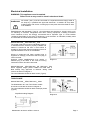
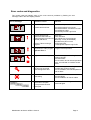
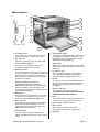
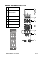
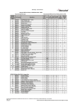
Mealstream 400
SERIES
SERVICE
MANUAL
Part No. 32Z3311 Issue No. 9
For all Mealstream 401 and 403 models for GB & Europe manufactured from January 2001
SERVICE MANUAL
Merrychef
CAUTION MICROWAVE EMISSIONS
DO NOT BECOME EXPOSED TO EMISSIONS FROM THE MICROWAVE
GENERATOR OR PARTS CONDUCTING MICROWAVE ENERGY
Mealstream 401Ovens 32Z3311 Issue 9
Page 1
Table of Contents
Safety Code...........................................................................3
Product Specifications ...........................................................4
Principles of Operation ..........................................................5
Installation Instructions ...................................................... 6-7
Error Codes and Diagnostics.................................................8
Main Features........................................................................9
Electronic Controls ..............................................................10
Manual Controls ..................................................................11
Power Output Testing to EN 60335-2-90 ............................12
Power Output Testing..........................................................13
Power Transformer Test......................................................13
High Voltage Capacitor Test................................................14
High Voltage Rectifier Test..................................................14
Magnetron Test ...................................................................14
Door Interlock Operation .....................................................15
Error Light Operation ..........................................................15
Casework.............................................................................16
Door Mechanism .................................................................17
Oven Cavity Components & Hot Air System .......................18
Oven Door Assembly...........................................................19
Magnetron & Door Interlock Components ...........................20
Magnetron & Door Interlock Components ...........................21
Major Electrical Components...............................................22
Input Wiring, Filters and Fuses............................................23
Input Wiring, Filters and Fuses............................................24
HT Components ..................................................................25
HT & Principal components: RMC1003__XX5/XX52 ..........26
Electronic Control Panel Assembly .....................................27
Manual Controls Panel Assembly........................................28
Membrane Panel Circuit ......................................................29
Complete Spare Part Listing.......................................... 30-31
Circuit Diagrams ............................................................ 32-38
Appendix 1 MenuKey Download Procedure........................39
Appendix 2 Cleaning Procedure..........................................40
Appendix 3 Transformer Replacement................................44
Manual corrections and modifications .................................45
Merrychef Limited,
Station Road West,
Ash Vale, Aldershot
Hampshire GU12 5XA
United Kingdom
Tel: +44 (0)1252 371000 Fax: +44 (0)1252 371007
Internet address: http://www.merrychef.com
E-mail: [email protected] or [email protected]
Merrychef and MenuKey™ are registered Trademarks of Merrychef Ltd.
Mealstream 401Ovens 32Z3311 Issue 9
Page 2
SAFETY CODE
This manual is designed to assist engineers who have been on a recognised product familiarisation
and training course run by Merrychef Limited. It has been prepared to offer technical guidance for the
Merrychef Mealstream 400 range of Combination Microwave Ovens.
Please remember that it is wiser not to attempt a service task if you are unsure of being able to
complete it competently, quickly, and above all safely.
To avoid injury to yourself, and to protect the appliance from possible damage, please follow this
Safety Code when servicing these ovens.
Before attempting to repair the oven, check it for microwave leakage.
Check that the oven is not emitting microwaves, even when supposedly not
in operation.
Check that the oven is not operating continuously, whether the display
indicates cooking or not.
Always discharge the HT capacitors before working on the oven using a
suitably insulated 10 MΩ Resistor
Before removing the rear cover from the oven ensure you do the following:
•
•
Switch off the mains supply and remove the plug from the wall socket.
or
If the oven is hard wired, ensure that the power is turned off at the isolator switch.
Note: the On/Off switch on the oven is not adequate protection against electric shock, as it does
not isolate all of the internal wiring from the Electrical Supply.
Upon completion of a service on a Mealstream 401/403 oven, or before reconnecting the appliance
to the mains supply for testing, check all of the following points:
•
•
•
•
•
•
•
•
All internal electrical connections are correct.
All wiring insulation is correct and is not touching a sharp edge.
All Earth connections are electrically and mechanically secure.
All four door safety interlocks are secure and mechanically sound.
The door operation is smooth, and the arms run freely in the slots.
The door activates all four of the door interlock switches in the correct order.
All fuse-holder safety covers are correctly fitted.
The temperature sensor is correctly connected to the Power PCB.
Before finishing the service call, recheck the following points:
•
•
•
•
•
All of the electronics are functioning correctly, and all of the touch pads are working.
The turntable is rotating correctly.
The power output of the oven is correct (see pages 12 & 13 ).
Microwave emission is below permissible limit - 5 mW/cm² (see BS EN 60335-2-90).
Oven has correct 50mm air gap all round and 150mm above.
Air flow should not be restricted.
Mealstream 401Ovens 32Z3311 Issue 9
Page 3
Product specifications: Mealstream 401 & 403 models
ELECTRONIC CONTROLS: ( EC401 & EC403 models )
Model No.: RMC1003 + Voltage + Frequency + Current + Controls
+ Phase + MenuKey + Catalytic converter
For example:
Model
prefix
RMC100345XE52MK
230-240V, 50Hz, 30A, Series 5 Controls, Twin Phase, MenuKey
Voltage
Frequency
Current
RMC1003 2 = 220-230V a.c. 5 = 50 Hz EE = 13A
4 = 230-240V a.c. 6 = 60 Hz
XE = 30A
Control Supply MenuKey Catalytic
converter*
Type
Phase
5=
Series 5
controls
2=
Twin
Phase
MK
C
XX = 30A
* A Catalytic converter is fitted to Mealstream 403 models only
MANUAL CONTROLS ( RD401 models )
Model No.: RMC1003 + Voltage + Frequency + Current
Model prefix
RMC1003
Voltage
Frequency
2 = 220-230V a.c.
4 = 230-240V a.c.
5 = 50 Hz
6 = 60 Hz
Power
Requirements
Current
CD2 = 13amp
XD2 = 30amp
See RATING PLATE on rear of oven
Power Output
(IEC 705)
Microwave 100%
Convection
Combination
700W
3000W
700W
700W
1000W
(_EE, _XE)
(_XX5 )
+ 1500W ( _EE )
+ 3000W ( _XE )
+ 3000W ( _XX5 )
External
Dimensions
Height
Width
Depth
530 mm (Plus 150 mm minimum clearance above)
550 mm (Plus 50 mm minimum clearance each side)
575 mm (Plus 50 mm clearance behind)
Internal
Dimensions
Height
Width
Depth
Turntable
Capacity
315 mm
330 mm
330 mm
300 mm Diameter
34.3 litres
Weight
Nett
Gross packed
All models except XX5 45kg,
All models except XX5 58kg,
Construction
Cavity
Casework
Vitreous Enamel Coated Steel
304 Stainless Steel
Anodised Aluminium Extrusions
Settings
Microwave
Temperature
Timer
100%,75%,50%,25%, Convection only
Off, 175°C, 200°C, 225°C, 250°C, 275°C
Up to 30 minutes
XX5 55kg
XX5 68kg
Up to 3 cooking stages of up to 30 minutes each
(Programmed)
Mealstream 401Ovens 32Z3311 Issue 9
Page 4
Principles of operation
Mealstream 401Ovens 32Z3311 Issue 9
Page 5
Installation instructions
Positioning the Oven
In order to maintain adequate ventilation for air intake and exhaust, and to allow access for
cleaning the air filters, you must allow a minimum of 50mm clearance at the sides and rear of
the oven, and at least 150mm above. Air intake temperature should not exceed 35°C.
Excessive temperature will lead to reduced operating duty cycle or premature ageing of
internal components.
NEVER
Install an oven above fryers, grills, griddles or any other major heat source.
NEVER
Stack machines on top of each other - always use a double stand.
ALWAYS
Place containers in the cavity carefully - impact damage may chip the
vitreous enamel coating.
Mealstream 401Ovens 32Z3311 Issue 9
Page 6
Electrical installation:
WARNING: This appliance must be earthed.
Failure to do so may result in electric shock and death
All models ( 30A ) must be connected to a separate electrical supply rated at
WARNING 30 Amps by a qualified and approved electrician. A suitable 30 amp rated
isolating switch with a 3mm contact gap on both poles should be fitted for each
oven installed.
Establishments with standard ( Type ‘B’ ) circuit breakers are sensitive to ‘surges’ which occur
on switching on freezers, refrigerators and other catering equipment, including microwave
ovens. Because of this, we strongly recommend that a separate Type ‘C’ circuit breaker
( designed specifically for this type of equipment ) must be fitted. An individual, suitably rated
circuit breaker should be fitted for each oven installed.
Models RMC1003__EE5, RMC1003__CD2
The power outlet used must be individually fused. It
is essential that the socket is properly installed and
earthed. It should be fed from a circuit which is
suitable for high power electrical appliances and it is
important that this circuit is not overloaded.
Where an approved and fitted moulded plug is
supplied we strongly recommend that this plug is
never removed.
However certain establishments may require a
different plug to be fitted. In this case, the wiring
instructions shown should be observed.
Diagram 1
Models RMC1003__XE5, RMC1003__XD, RMC1003__XX5
When supplied, single phase models are fitted with a
Blue 32Amp Plug approved to BS4343. Wiring cable
colours as shown in Diagram 1
The Circuit Breaker should be rated at 45A (TypeC).
TWIN PHASE
Models RMC1003__XE52, RMC1003__XX52
The Mealstream 401 oven Twin Phase models
should be connected as shown in Diagram 2.
The Circuit Breaker should be rated at 20A per phase
(TypeC).
Simplified loading Diagram
Mealstream 401Ovens 32Z3311 Issue 9
Diagram 2
Page 7
Error codes and diagnostics
The control panel will identify some of the most common problems by flashing an error
message code in the time display window.
Error Message
Possible Cause
Service
1
Door not fully shut
Close door fully.
2
Possible electrical fault
Check Microswitch Door Circuit
Check Microswitch Connection to PCB
Check Ribbon Cable
Check Relay PCB & Logic PCB
1
2
3
4
No time has been set
Invalid time has been set
Invalid program has been set
Number pad failure
5
Memory Failure running a
Program
Set a time
Set a valid time
Use call-back to check program
(Menukey: no key downloaded)
Membrane key short circuit
Re-Program Pad,
if fault repeats replace Logic PCB
1
Oven is not at correct
temperature to start program
Operator Error !!
Allow oven to reach correct
Programmed temperature
1
Magnetron overheating
Check that magnetron cooling fan is
working correctly
Check air filters
Check location and air inlet temperature
Note : this will lead to condition shown
below
1
Magnetron has overheated
but has now recovered
Internal diagnostic fault
Check that magnetron cooling fan and
turntable are working correctly
Check installation, air inlet temperature
and air filters
Oven control area is
overheating
Check air filters.
Check axial fan
Check installation for hot air intake
2
1
MenuKey removed before the Switch oven off and begin the MenuKey
download is complete
download again
or the process has been
interrupted
Mealstream 401Ovens 32Z3311 Issue 9
Page 8
Main features
a
b
d
c
e
p
g
f
h
q
n
j
b
l
rear view of Oven
k
m
a STEAM OUTLET
Allows steam and excess pressure to escape
from the oven cavity. It must be kept clear.
b AIR OUTLET
Warm air is vented here. It must be kept clear.
c TRAY HANDLE RESTS
There is one on each side of the oven for
convenient storage of the tray handle.
d BAFFLE PLATE
Forms the inside rear of the oven and covers the
hot air circulation fan. Removable for cleaning by
unscrewing the four wing nuts which hold it in
place. This must be cleaned on a regular basis,
and kept free of debris.
BAFFLE PLATE & CATALYTIC
CONVERTOR (EC403 model only)
Allows extraction free cooking. Should be removed
regularly for cleaning. ( Do not spray/put caustic
cleaner directly into the catalytic converter as this will
cause permanent damage )
e RUNNERS
These mounted on each side of the oven cavity
to support the rectangular racks or oven trays,
and are for use in Convection mode only.
f HOT AIR FAN
Situated behind the baffle plate, and circulates
the hot air through the baffle plate, over the
heating element, and around the edge of the
baffle plate back into the cavity.
g OVEN CAVITY
h TURNTABLE TRAY
The vitreous enamelled turntable tray fits onto the
turntable disc in the bottom of the oven cavity,
and rotates during cooking to ensure an even
distribution of microwave energy.
i AIR INLETS
Additional air inlets are situated along the lower
edge of the left-hand side panel, and must not be
obstructed.
j RATING PLATE
The rating plate is situated on the rear of the
oven, and states the Model, Serial Number,
Electrical Ratings and Manufacturers Tel no.
k DOOR
The door consists of a thermally insulated inner
section, and an additional air gap provided by a
twin skinned door front to lower the surface
temperature.
l ON/OFF SWITCH
This is used to turn the oven On or Off.
IT DOES NOT ISOLATE INTERNAL WIRING
FROM THE ELECTRICAL SUPPLY.
m FEET
These feet are fitted to ensure adequate airflow
under the oven. They must not be removed.
n ELECTRICAL SUPPLY LEAD
p AIR FILTER
Main intake for cooling air for internal
components. Must be clear of obstructions.
q MenuKey
The oven cavity is mainly constructed form
vitreous enamelled steel panels. It must be kept
clean.
Mealstream 401Ovens 32Z3311 Issue 9
Page 9
Electronic controls: Mealstream EC401, EC403
a
Stage LED's
b
Service Indicator
a
c
Air Filter Block Indicator
b
d
Operator error indicator
c
e
Program Display
d
f
Temperature Set Pads
g
Time / Program Number Pads
h
Cancel/ Callback Pad
i
Program Pad
j
Convection Pad
k
Microwave power Pads
l
On/Off switch
e
m
f
g
MenuKey socket
i
1
2
3
0
175
200
225
250
275
1
2
3
4
5
6
7
8
9
P
0
C
h
j
k
25%
75%
l
m
50%
100%
Starbucks model
Mealstream 401Ovens 32Z3311 Issue 9
Page 10
Manual controls: Mealstream RD401
a
b
a
Temperature Amber Neon
b
Temperature Control
c
Microwave Power Control
d
Timer
e
Start Pushbutton
f
Cook cycle Red Neon
g
Power Amber Neon
h
On/Off switch
c
d
e
f
g
h
Mealstream 401Ovens 32Z3311 Issue 9
Page 11
Procedure A - Power Output Test
In accordance with BS EN 60335-2-90
This test is given in the BSI test standard for microwave ovens. It is reproduced below - not so that
you can follow it, but to show you why it is impractical in normal conditions. A simplified procedure,
which gives a good approximation to the BSI power output, is given in Procedure B which follows.
Note: This test can only be carried out on a COLD oven. If the oven has been operating, even for
only a few seconds, the power given will be lower than the oven rating. This test must also be carried
out at a stable voltage - the voltage in most kitchens varies considerably even within the period of the
test. If the oven has been operating, go to Procedure B.
You will need:
A thermometer capable of reading to ±0.1°C.
A cylindrical borosilicate glass container, 190 mm diameter, with a wall thickness of 3 mm or less.
A calculator.
A set of scales capable of reading 1 kg to an accuracy of ± 1 g.
A glass or plastic stirrer.
A jug capable of holding over 1 litre of water.
Drinkable water which is at a temperature of 10°C ± 1°C.
A “Variac” or similar variable transformer capable of supplying the oven to ensure a stable voltage.
WARNING: The Borosilicate Glass container has thin walls and is therefore fragile
- take care not to break it during use.
Method
A cylindrical container of borosilicate glass is used for the test. It has a maximum thickness of
3mm, an external diameter of approximately 190mm and a height of approximately 90mm. The
mass of the container is determined.
At the start of the test, the oven and the empty container are at ambient temperature. Potable water
having an initial temperature of 10°C ± 1°C is used for the test. The temperature of the water is
measured immediately before it is poured into the container.
A quantity of 1000g ± 5g of water is added to the container and its actual mass obtained. The
container is then immediately placed in the middle of the oven on the turntable. The appliance is
supplied at rated voltage and operated at the maximum power setting. The time for the water
temperature to attain 20°C ± 2°C is measured. The oven is then switched off and the final water
temperature is measured within 60seconds.
NOTES
1 The water is stirred before its temperature is measured.
2 Stirring and measuring devices are to have a low heat capacity.
The microwave power output is calculated from the formula:
P=
4.187 MW (T2-T1) + 0.55 MC (T2-T0)
t
where
P
MW
MC
T0
T1
T2
t
is the microwave power output, in watts;
is the mass of the water, in grams;
is the mass of the container, in grams;
is the ambient temperature, in °C;
is the initial temperature of the water, in °C;
is the final temperature of the water, in °C;
is the heating time in seconds, excluding the magnetron filament heat-up time.
Mealstream 401Ovens 32Z3311 Issue 9
Page 12
Procedure B - Simplified Power Output Test
You will need:
A thermometer capable of reading to ±0.1°C.
A Polypropylene tray approximately 200 mm x 200 mm.
A measuring jug.
A calculator.
Water which is at a temperature of 10°C ± 2°C.
1
2
3
4
5
6
7
8
Measure 1 litre of cold water into the tray using the measuring jug.
Measure the water temperature, and record it as T[s].
Place the tray on the turntable in the oven and close the door.
Turn the oven on.
Set the timer to 1:02. ( For Manual controls use a stopwatch set to 1 minute 2 seconds )
Press the “100%” power pad.
When the oven bleeps, open the door and remove the tray.
Stir the water thoroughly, and measure its temperature. Record this as T[e].
Calculation:
1
2
T[r] = T[e] - T[s].
Power = 70 x T[r]. Power is in Watts.
The power given by the above test should be within ±10% of the rated power.
Procedure C - Power Transformer Test
You will need:
A Digital Multi-meter (D.M.M.)
A Megger or similar resistance meter using 500V d.c.
1 Isolate the oven from the mains supply.
WARNING: High voltages and large currents are present at the secondary winding and filament
winding of the Power Transformer. It is very dangerous to work near this part when the
oven is on. NEVER make any voltage measurements at the High Voltage circuits,
including the magnetron filament.
WARNING: Even when the oven is not cooking, the Power Transformer has High Voltages present
because of the Soft Start circuit. Isolate the oven before testing.
2
3
4
Ensure that the High Voltage Capacitor is discharged before commencing work.
Remove all connections from the Power Transformer.
Using a D.M.M., check the continuity of the windings. Results should be as follows:
a
Mains winding between tags
b
High Voltage winding
c
Filament winding
between terminals
5
Using a Megger, test the insulation resistance between:
Approx. 1.3 Ω
c
Approx. 50-100 Ω
b
Less than 1 Ω
Primary winding and chassis
Pass if over 10 MΩ
Filament winding and chassis
Pass if over 10 MΩ
a
One end of the High Voltage winding is connected to the
chassis, so this is not tested.
Mealstream 401Ovens 32Z3311 Issue 9
Page 13
Procedure D - High Voltage Capacitor Test
You will need:
A Digital Multi-meter (D.M.M.)
A Megger or similar resistance meter using 500V d.c.
WARNING: High voltages and large currents are present at the High Voltage Capacitor. It is very
dangerous to work near this part when the oven is on. NEVER make any voltage
measurements at the High Voltage circuits, including the magnetron filament .
WARNING: Even when the oven is not cooking, the High Voltage Capacitor has High Voltages
present because of the Soft Start circuit. Isolate the oven before testing.
1. Isolate the oven from the mains supply.
2. Ensure that the High Voltage Capacitor is discharged before
commencing work.
3. Remove all connections from the High Voltage Capacitor.
4. Using a D.M.M., check for continuity between the terminals &
Between Terminals
Pass if approximately 10 MΩ
Between Terminals and Case
Pass if open circuit
5. Using a Megger, test the insulation resistance between the
terminals and the case.
Between Terminals and Case
Pass if over 100 MΩ
Procedure E - High Voltage Rectifier Test
You will need:
A Megger or similar resistance meter using 500V d.c.
WARNING: High voltages and large currents are present at the High Voltage Rectifier. It is very
dangerous to work near this part when the oven is on. NEVER make any voltage
measurements at the High Voltage circuits, including the magnetron filament .
WARNING: Even when the oven is not cooking, the High Voltage Rectifier has High Voltages
present because of the Soft Start circuit. Isolate the oven before testing.
1. Isolate the oven from the mains supply.
2. Ensure that the High Voltage Capacitor is
discharged before commencing work.
3. Remove all connections from the High Voltage
Rectifier.
4. Using the Megger, test for continuity in both
directions. Compare results with the table.
Open Circuit both ways
FAIL
Conducts one way only
PASS
Short Circuit both ways
FAIL
Conducts one way, leaks the other
FAIL
Procedure F - Magnetron Test
You will need:
A Megger or similar resistance meter using 500V d.c.
A Magnetron can be tested for an open filament or a short circuit
by carrying out a continuity check.
1. Isolate the oven from the mains supply.
2. Ensure that the High Voltage Capacitor is discharged before
commencing work.
3. Remove all connections from the Magnetron.
4. A continuity check across the Filament terminals should be 1ohm or less
5. A continuity check between each filament terminal and the
metal outer should read open.
Mealstream 401Ovens 32Z3311 Issue 9
Page 14
Door interlock operation
The door on the oven is monitored by four microswitches. Three of these are used in the
conventional “Primary, Secondary and Monitor” switch arrangement shown below, while the fourth
is a low-voltage switch linked directly to the control circuitry.
The switches operate as follows:
56
Door Interlock Arrangement
Top RH
57
L
Power In
Bottom Inner
Top LH 55
Bottom Outer
58
Power Out
N
1. Primary Interlock [ 55 , Top Left-Hand ] and Low voltage [ 56 , Top Right-Hand ]
Switches
Operate simultaneously. Either will cut off the microwave emissions from the oven when the
door is opened: the Primary switch by breaking the mains supply circuit to the transformers,
and the Low-Voltage switch by breaking the relay circuit on the Power / Relay PCB.
2. Monitor [ 58 , Bottom Outer ] and Secondary Interlock [ 57 , Bottom Inner ]
Switches.Operate simultaneously. The Monitor switch will produce a short circuit across
the mains supply if the Primary interlock switch is faulty, thus blowing the microwave fuse
and rendering the oven inoperative. The Secondary interlock switch will cut off the
microwave emission if all three of the other switches have failed.
Note: If operation of the Monitor switch has caused the Microwave Fuse to blow, the
Primary and Monitor microswitches must be changed, as they may have been
damaged by the high short-circuit currents involved.
Error Light Operation
The “Air Filter Blocked” light and “Service” light are triggered by the internal circuitry. If the
magnetron overheats, the error code “E:7” is displayed on the front panel, and both the “Air Filter
Blocked” and the “Service” indicators will light. Once the magnetron has cooled sufficiently to allow
the oven to restart, the “Service” light will remain illuminated until the oven is turned off.
This fault may have been triggered by one of the following causes:
- Air inlet on rear of machine being obstructed.
- High air inlet temperature.
- Slow running cooling fan, jammed turntable or broken gearbox
(cooling fan also drives turntable).
- Faulty magnetron overheat ‘stat or associated wiring.
Note that the customer may not have noticed that the oven displayed “E:7”, and so the
reported fault may be misleading.
Mealstream 401Ovens 32Z3311 Issue 9
Page 15
Principal components: casework
105
96
104
105A
MC3134
9
Handle Hanger
RCK6319
RMC6773
10
Rubber Foot
RMC6104
MC3120X01
11
Front Lower Panel
MC3047
Top Plate
RMC6759E
12
Lower Trim
MC3122
5
Exhaust Gallery
RMC73372
96
PCB Retainer LH
40H0083
6
Rear Panel
MC3129
104
PCB Retainer RH
40H0084
7
Air Filter
MC3155
105
Side Trim LH
MC31211
8
Side Panel (R/H)
MC3133
105A Side Trim RH
MC31212
1
Side Panel (L/H)
2
Ferrite
3
Upper Trim
4
Mealstream 401Ovens 32Z3311 Issue 9
Page 16
Door mechanism
13
Door Stay (R/H)
14
Hinge Body
15
Hook (A)
RMC66171
16
Hook (B)
RMC66172
17
Door Spring (B)
18
Hinge Body (L/H)
19
Door Spring (A)
MC3067
20
Door Stay (L/H)
MC3046
21
Microswitch Guide
40H0076
22
Solid Door Assy Black
11H0071
22
Solid Door Assy Silver
MC3230X02
Mealstream 401Ovens 32Z3311 Issue 9
MC3040
MC30121X02
MC3068X01
MC30122X01
Page 17
Oven cavity components and hot air system
401 models
25
136
137
403 models
137
136A
135
25
23
Turntable Disc
RMC7340X01
34
Motor Bracket
24
Baffle Plate Bolt
CP30326
35
Cushion Rubber
RCK8273
25
Baffle Plate
MC3018
36
Motor Fixing Screw
CP30310
26
Fan Fixing Cap
RCK7617
37
Hot Air Motor
27
Fan
MC3111
28
Partition Plate
11H0007
29
Cavity Sealing Glass
30
Oven Body
MC3013
31
Gearbox
MC3216
32
Shaft
33
Cooling Fan
RMC7043
RMC7391X01
RMC7307X01
MC3110
135
Catalytic Converter
31Z1245
136
Cat. Cover
40H0221
136A Vent Plate
40H0236
137
Thumb nut
31Z4031
RMC7310
Mealstream 401Ovens 32Z3311 Issue 9
Page 18
Oven door assembly
Solid door assembly, Silver MC3230X02
Solid door assembly, Black 11H0071
22
Solid Door Assy.
Silver
11H0031
22
Solid Door Assy Black
11H0071
38
Door Handle Silver
39
Door Frame (A) Black
MC30503
40
Door Cover Outer
Silver
40H0080
40
Door Cover Outer
Black
40H0082
41
Inner Panel
40H0081
42
Door Reinforcement
43
Door Frame (B)
MC3055
44
Insulation Wrap
32Z0001
46
Door Base Silver
47
Door Cover
MC3064
48
Plate - Door Switch
MC3056
52
Packing (B)
MC3065
53
Door Rear Plate
Mealstream 401Ovens 32Z3311 Issue 9
RBR1285048
RMC70722
MC3031KX04
MC3066X01
Page 19
Magnetron and door interlock components
Model RMC1003__EE5
Model RMC1003__XE5
*If replacing a Sanyo Magnetron with a Panasonic
Magnetron the HV capacitors need to be changed:
XE & EE models
1.1 to 1.0µF (30Z1241)
54 Door Switch Bracket
40H0023
62
Inlet Duct
55 Primary Microswitch
30Z0240
63
*Magnetron
30Z1171
56 Low Voltage Microswitch
30Z0240
64
Magnetron Cut-out
30Z0088
57 Secondary Microswitch
30Z0240
65
Switch Bracket
58 Monitor Microswitch
30Z0240
66
Blower Assembly
MC3141
59 Microswitch Insulator
31Z0115
67
M3 x 25 Pan Head Pozi
31Z3093
60 Outlet Duct
MC3037
68
M3 x 30 Pan Head Pozi
31Z3118
61 Foam Tape
31Z0042
Mealstream 401Ovens 32Z3311 Issue 9
RMC7193X01
RMC7101X01
Page 20
Magnetron and door interlock components
Model RMC1003__XX5
Model RMC1003__XX52
129
133
128
128
*If replacing a Sanyo Magnetron with a Panasonic
Magnetron the HV capacitors need to be changed:
XX5 models
0.88 to 0.75µF (30Z1250)
54 Door Switch Bracket
40H0023
64
Magnetron Cut-out
55 Primary Microswitch
30Z0240
65
Switch Bracket
56 Low Voltage Microswitch
30Z0240
67
M3 x 25 Pan Head Pozi
31Z3093
57 Secondary Microswitch
30Z0240
68
M3 x 30 Pan Head Pozi
31Z3118
58 Monitor Microswitch
30Z0240
128 Cooling Fan 230V 50Hz
30Z1128
59 Microswitch Insulator
31Z0115
128 Cooling Fan 230V 60Hz
30Z1190
60 Outlet Duct
MC3037
129 Turntable Motor
61 Foam Tape
31Z0042
133 Inlet Duct
63 *Magnetron
30Z1171
Mealstream 401Ovens 32Z3311 Issue 9
30Z0088
RMC7101X01
RMC5055EX
40H0176
Page 21
Major electrical components
See Pages 23-25
64
Magnetron Overheat Switch
30Z0088
74
Temperature Sensor
50E123
69
Cavity Overheat Switch
30Z1031
75
HV Diode Assembly
11H0010
70
Bridge Rectifier (__EE only)
71
No. 8 Screw
72
M5 Screw
73
Heating Element 220V
40H0077
73
Heating Element 240V
40H0009
341520
117 Axial Fan, 80mm
310010
31Z3107
101825
Mealstream 401Ovens 32Z3311 Issue 9
Page 22
Input wiring, filters and fuses
Model RMC1003__XE5, XD
Model RMC1003__EE5, CD2
Green / Yellow
Green / Yellow
Blue
Blue
Brown
Brown
111
112
112a
115
111
Mains Input Block
31Z0328
112
Cable Gland
31Z1070
112A Cable Gland Nut
113
Input Cable Assembly
115
XE5 Input Cable Assembly
116
Strain Relief Grommet
111
116
113
31Z1082
31Z0220
302030
31Z1036
82
78
79
81
77
80
79
81
77 Microwave Mains Filter 16A
30Z0997
78 Heater Mains Filter 16A
30Z0997
79 Fuse Cover
20Z1080
80 Fuse 10A HRC
30Z0217
81 Fuse Holder 1”
30Z0231
82 Fuse 13A
30Z0456
Mealstream 401Ovens 32Z3311 Issue 9
Page 23
Input wiring details: Model RMC1003__XX5, XX52
Green / Yellow
Green / Yellow
Blue
Blue
Brown
L2
111
112
112a
L1
115
111
111
Mains Input Block
31Z0328
112
Cable Gland
31Z1070
112A Cable Gland Nut
113
Input Cable Assembly
31Z1082
31Z0220
XX5 Input Cable Assembly
116
Strain Relief Grommet
31Z1036
78
77
82
81
80
81
77 Microwave Mains Filter 16A
30Z0997
78 Heater Mains Filter 16A
30Z0997
80 Fuse 10A HRC
30Z0217
81 Fuse Holder 1”
30Z0231
82 Fuse 13A
30Z0456
Mealstream 401Ovens 32Z3311 Issue 9
Page 24
HT Components: RMC1003__EE5/ XE5
75
HV Diode Assembly
11H0010
88
HT Transformer Top Bracket
MC3127
89
HV Lead Assembly, Ferrite
11H0025
90
*Transformer 208-240V 50Hz
30Z1233
90
*Transformer 208-240V 60Hz
30Z1230
91
HT Transformer Bottom
Bracket
40H0070
92
Capacitor Band
93
Filter Bracket
40H0065
94
HT Transformer Support
Bracket
MC3024
76
Oven Type
Capacitor
Part No.
Value
50Hz EE, XE,
CD2, XD2
30Z1331 x1
1.0uF 2500V
60Hz EE, XE
30Z1329 x1
0.75uF 2500V
RMC7215
*Transformer replacement see Appendix 3
Mealstream 401Ovens 32Z3311 Issue 9
Page 25
HT & principle components: Models RMC1003__XX5, RMC1003__XX52
Right
side
102
130
132
128
90
90
76
76A
76A Capacitor Clip
30Z1237
90
*Transformer 208-240V 50Hz
30Z1233
90
*Transformer 208-240V 60Hz
30Z1230
102
Resistor 470R 50W (Gold)
30Z0283
128
Cooling Fan 230V 50Hz
30Z1128
128
Cooling Fan 230V 60Hz
30Z1190
130
Diode Board
11H0058
132
Heater Relay
30Z0986
*Transformer replacement see Appendix 3
76
Oven Type
50Hz XX5
60Hz XX5
Capacitor
Part No.
Value
30Z1329 x2
0.75uF 2500V
30Z0385 x1
0.6uF 2500V
30Z1329 x1
0.75uF 2500V
Mealstream 401Ovens 32Z3311 Issue 9
Page 26
Electronic control panel assembly
100
110
102
98
101
99
107
1
2
3
0
175
200
95
225
250
275
108
1
2
3
4
5
6
7
8
9
P
0
C
107
103
25%
110
75%
50%
100%
107
100
97
109
Membrane Panel
Menukey
(Blue)
Model
97
131
95
Membrane Assy
97
On/Off Switch
98
Logic Assy.
99
Support Shield
See Table
Membrane Panel
Starbucks
(Red/ Grey)
Membrane Assy Logic PCB
EE5, XE5, XX5
11H0060
11C0285
XX5 Starbucks
11H0024
11C0285
EE5, XE5, XX5
Menukey
11H0067
11C0066
XX5 Locare
11H0073
11C0066
103 Relay Assy. (_EE)
11C0286
103 Relay Assy. ( _XE, _XX5)
11H0077
103 Relay Assembly Starbucks
11H0201
40H0075
107 PCB Stand-off
31Z7010
100 M3 x 5 Screw
31Z3106
108 15 Way Ribbon Connector
11Z0298
101 No. 4 x 3/8” Screw
31Z3112
109 Single 0.25” Blade Tag
102 470R 50W Resistor
30Z0283
110 M3 Nylon Support
31Z0206
131 Menukey Assembly
10C0148
30Z0503
See Table
Mealstream 401Ovens 32Z3311 Issue 9
309610
Page 27
Manual control panel assembly
96
123
124A
121
124B
124C
124D
122
125
105A
126
97
123
96
PCB Retainer LH
40H0083
97
On/Off Switch
30Z0503
104
PCB Retainer RH
40H0084
105A Side Trim RH
M5 Flat Washer
31Z5004
121
PCB Assembly
11H0027
122
Timer
30Z0991
123
Amber Neon
316031
124A Control Knob Black
313020
124B Control Knob Skirt Red
313160
124B Control Knob Skirt Blue
31Z1216
124C Control Knob Cap Red
313220
124C Control Knob Cap Blue
31Z1217
11C0173
124E Control Knob Assy Blue
11C0406
Pushbutton (Start)
126
Red Neon
127
Potentiometer
Mealstream 401Ovens 32Z3311 Issue 9
127
122
313030
124E Control Knob Assy Black/Red
125
104
MC31212
106
124D Control Knob Shaft Adaptor
106
31Z0349
316030
40C0892
Control Board not
shown for clarity
Page 28
Membrane panel circuit
You will need:
A Digital Multi-meter (D.M.M.)
1. Isolate the oven from the mains supply.
2. Remove the Logic Assembly from the Control
Panel Housing.
3. Unplug the membrane “tail” from the Logic
PCB Assy.
4. Using a D.M.M., check for continuity between
the correct terminals when the pads are
pressed.
5. When the panel has been tested,
re-assemble and re-test the control housing.
Mealstream 401Ovens 32Z3311 Issue 9
Page 29
Part number identification chart 1
1
SIDE PANEL (L/H)
MC3134
41
INSULATION PANEL
2
FERRITE
3
UPPER TRIM
4
RMC6773
42
DOOR REINFORCEMENT
MC3120X01
43
DOOR FRAME (B)
MC3055
TOP PLATE
RMC6759E
44
INSULATION WRAP
32Z0001
5
EXHAUST GALLERY
RMC73372
46
DOOR BASE SILVER
6
REAR PANEL
MC3129
47
DOOR COVER
MC3064
7
GREASE FILTER
MC3155
48
PLATE - DOOR SWITCH
MC3056
8
SIDE PANEL (R/H)
MC3133
52
PACKING (B)
MC3065
9
HANDLE HANGER
RCK6319
53
DOOR REAR PLATE
10
RUBBER FOOT
RMC6104
54
DOOR SWITCH BRACKET
11
FRONT LOWER PANEL
MC3047
55
PRIMARY MICROSWITCH
12
LOWER TRIM
MC3122
13
DOOR STAY (R/H)
MC3040
56
LOW VOLTAGE MICROSWITCH
14
HINGE BODY
57
SECONDARY MICROSWITCH
15
HOOK (A)
RMC66171
58
MONITOR MICROSWITCH
16
HOOK (B)
RMC66172
59
MICROSWITCH INSULATOR
31Z0115
17
DOOR SPRING (B)
MC3068X01
60
OUTLET DUCT
MC3037
18
HINGE BODY (L/H)
MC30122X01
61
FOAM TAPE
31Z0042
19
DOOR SPRING (A)
MC3067
62
INLET DUCT
RMC7193X01
20
DOOR STAY (L/H)
MC3046
63
*MAGNETRON
30Z1171
21
MICROSWITCH GUIDE
40H0076
64
MAGNETRON CUT-OUT
30Z0088
22
SOLID DOOR ASSY SILVER
MC3230X02
65
SWITCH BRACKET
22
SOLID DOOR ASSY BLACK
11H0071
66
BLOWER ASSEMBLY
23
TURNTABLE DISC
24
BAFFLE PLATE BOLT
25
BAFFLE PLATE
26
FAN FIXING CAP
27
FAN
MC3111
28
PARTITION PLATE
11H0007
29
CAVITY SEALING GLASS
30
OVEN BODY
31
GEARBOX
32
SHAFT
33
COOLING FAN
34
MOTOR BRACKET
35
MC30121X02
RMC7340X01
40H0081
RMC70722
MC3031KX04
MC3066X01
40H0023
30Z0240
RMC7101X01
MC3141
(NOT RMC1003__XX5, XX52)
67
M3 X 25 PAN HEAD POZI
31Z3093
68
M3 X 30 PAN HEAD POZI
31Z3118
69
CAVITY OVERHEAT SWITCH
30Z1031
70
BRIDGE RECTIFIER (EE ONLY)
71
N0. 8 SCREW
72
M5 SCREW
MC3013
73
73
240V HEATING ELEMENT
220V HEATING ELEMENT
40H0009
40H0077
MC3216
74
TEMPERATURE SENSOR
50E123
RMC7391X01
75
HV DIODE ASSEMBLY
11H0010
RMC7310
76
HT Capacitor 1.0µF
30Z1331
RMC7307X01
76
HT Capacitor 0.88µF
30Z1075
CUSHION RUBBER
RCK8273
76
HT Capacitor 0.6µF
30Z0385
36
MOTOR FIXING SCREW
CP30310
76
HT Capacitor 0.75µF
30Z1329
37
HOT AIR MOTOR
38
DOOR HANDLE SILVER
39
DOOR FRAME (A) BLACK
MC30503
40
DOOR OUTER BLACK
40H0080
40
DOOR OUTER SILVER
40H0082
CP30326
MC3018
RCK7617
RMC7043
MC3110
76A Capacitor Clip
341520
31Z3107
101825
30Z1237
RBR1285048
Mealstream 401Ovens 32Z3311 Issue 9
*If replacing a Sanyo Magnetron with a Panasonic
Magnetron the HV capacitors need to be changed:
XE & EE models
1.1µF to 1.0µF
(30Z1241)
Page 30
Part number identification chart 2
77
M’WAVE MAINS FILTER 16A
30Z0997
117
80MM AXIAL FAN
310010
121
PCB ASSEMBLY
11H0027
30Z0991
78
MAINS FILTER 16A
79
FUSE COVER
20Z1080
122
TIMER
80
FUSE 10A HRC
30Z0217
123
NEON AMBER
316031
81
FUSE HOLDER 1 INCH
30Z0231
124A
CONTROL KNOB BLACK
313020
82
FUSE 13A
30Z0456
124B
CONTROL KNOB SKIRT RED
313160
88
HT TRANSFORMER TOP
BRACKET
MC3127
124B
CONTROL KNOB SKIRT BLUE
124C
CONTROL KNOB CAP RED
89
HV LEAD ASSEMBLY
11H0025
124C
CONTROL KNOB CAP BLUE
90
*Transformer 208-240V 50Hz
30Z1233
124D
90
*Transformer 208-240V 60Hz
30Z1230
CONTROL KNOB SHAFT
ADAPTER
91
HT TRANSFORMER BOTTOM
BRACKET
40H0070
124E
CONTROL KNOB ASSY BLACK/
RED
11C0173
92
CAPACITOR BAND
RMC7215
124E
CONTROL KNOB ASSY BLUE
11C0406
93
FILTER BRACKET
40H0065
125
PUSHBUTTON (START)
31Z0349
94
HT TRANSFORMER SUPPORT
BRACKET
MC3024
126
NEON RED
127
POTENTIOMETER
40C0892
SEE TABLE
128
COOLING FAN 220/240V 50HZ
30Z1128
30Z1190
31Z1216
313220
31Z1217
313030
316030
95
MEMBRANE ASSEMBLY
96
PCB RETAINER LH
40H0083
128
COOLING FAN 220V 60HZ
97
ON/OFF SWITCH
30Z0503
129
TURNTABLE MOTOR
98
LOGIC ASSY.
SEE TABLE
130
DIODE BOARD
11H0058
99
SUPPORT SHIELD
40H0075
131
MENUKEY ASSEMBLY
10C0148
100
M3 X 5 SCREW
31Z3106
132
HEATER RELAY
30Z0986
101
NO. 4 X 3/8” SCREW
31Z3112
133
INLET DUCT
40H0176
102
470R 50W GOLD RESISTOR
30Z0283
135
CATALYTIC CONVERTER
31Z1245
103
RELAY PCB ASSY (_EE)
11C0286
136
CAT. COVER
40H0221
103
RELAY PCB ASSY( _XE, _XX5)
11H0077
136A
VENT PLATE
40H0236
103
RELAY PCB ASSY ( Starbucks)
11H0201
137
THUMB NUT
31Z4031
104
PCB RETAINER RH
40H0084
105
SIDE TRIM LH
MC31211
105A SIDE TRIM RH
MC31212
Model
RMC5055EX
Membrane
Assembly
106
M4 FLAT WASHER
31Z5004
107
PCB STAND-OFF
31Z7010
108
15 WAY RIBBON CONNECTOR
11Z0298
109
SINGLE 0.25” CONNECTOR
110
M3 NYLON SUPPORT
31Z0206
111
MAINS INPUT BLOCK
31Z0328
112
CABLE GLAND
31Z1070
CABLE GLAND NUT
31Z1082
98
RMC1003__EE5, XE5, XX5_, Haari
11C0285
113
INPUT CABLE ASSEMBLY
31Z0220
98
RMC1003__XX5 Starbucks
11C0285
115
XE5 INPUT CABLE ASSEMBLY
302030
98
11C0066
116
STRAIN RELIEF GROMMET
RMC1003__EE5, XE5, XX5_
Menukey
98
RMC1003__XX5 Locare
11C0066
112A
95
RMC1003__EE5, XE5, XX5_, Haari
11H0060
95
RMC1003__XX5 Starbucks
11H0024
95
RMC1003__EE5, XE5, XX5_
Menukey
11H0067
95
RMC1003__XX5 Locare
11H0073
309610
Model
31Z1036
*Transformer Replacement see Appendix 3
Mealstream 401Ovens 32Z3311 Issue 9
Logic PCB
Page 31
Circuit diagram: RMC 1003__XE (30A)
40H0233 Issue 9
Date: 05.2007
Mealstream 401Ovens 32Z3311 Issue 9
Page 32
200ºC
130ºC
Circuit diagram: RMC 1003__5 EE & RMC 1003__XE
40H0072 Issue 6
Date: 08.2004
Mealstream 401Ovens 32Z3311 Issue 9
Page 33
Circuit diagram: RMC 1003__5 EE & RMC 1003__XE (30A)
40H0233 Issue 9
Date: 05.2007
Mealstream 401Ovens 32Z3311 Issue 9
Page 34
Circuit diagram: RMC 1003__XX5 (30A)
40H0234 Issue 3
Date: 05.2007
Mealstream 401Ovens 32Z3311 Issue 9
Page 35
200ºC
130ºC
Circuit diagram: RMC 1003__XX5 (Single Phase)
40H0169 Issue 3
Date: 08.2004
Mealstream 401Ovens 32Z3311 Issue 9
Page 36
Circuit diagram: RMC 1003__CD2
40H0090 Issue 3
Date: 08.2004
Mealstream 401Ovens 32Z3311 Issue 9
Page 37
Circuit diagram: RMC 1003__CD2
40H0090 Issue 4
Date: 05.2007
Mealstream 401Ovens 32Z3311 Issue 9
Page 38
Circuit diagram: RMC 1003__5 EE & RMC 1003__XE ( Before August 2004 )
Mealstream 401Ovens 32Z3311 Issue 9
Page 39
Circuit diagram: RMC 1003__XX5 (Single Phase) ( Before August 2004 )
Mealstream 401Ovens 32Z3311 Issue 9
Page 40
Circuit diagram: RMC 1003__XX52 (Twin Phase) ( Before August 2004 )
Mealstream 401Ovens 32Z3311 Issue 9
Page 41
APPENDIX 1: MenuKey™ Download Procedure
The MenuKey System automatically changes all the cooking programs
on the numbered icon pads with the turn of a key.
To change the menus on the oven:
1
Ensure the power switch is off.
2
Lift the MenuKey cover in the
front panel of the oven and
put the key in the keyhole
Turn the key clockwise to the
stop ( ¼ turn ).
Do not remove the key at this
stage.
3
Switch the power switch on.
The oven will now go through the
program download sequence by
displaying the following:
The Key Code
example: Key C02
The number of programs and each
program number on the key.
example: 27 Programs
EPS - FAIL - REDO
External Program
System ERROR.
If the key is removed
before the download is
complete or the process is
interrupted the display
shows “EPS” then “FAIL”
then “REDO”. Switch the
oven off and begin the
MenuKey download again.
When the display shows 00:00
remove the key and close the cover.
The oven is now ready to use with the
new programs.
To confirm the download is successful
Switch off the oven.
Switch on and the display briefly will show the following:
1. The new key code
2. 00:00 (oven ready to use)
If the download is not successful the key number will not be
displayed and if the program pads are pressed an E3 error will
display.
Mealstream 401Ovens 32Z3311 Issue 9
Page 42
APPENDIX 2: Cleaning Procedure
Follow the SAFETY INSTRUCTIONS at the beginning of this manual.
• ALWAYS switch off at the electrical supply and allow oven to
cool for at least 20 minutes before cleaning
Faults arising from neglect
or misuse, including use
without clean filters in
place, are not covered by
the guarantee. Service
visits as a result of such
faults will be chargeable.
• As required, remove carousel and wipe out spillages with
disposable paper wipes
• NEVER use steel wool, knives or harsh abrasives on any part
of the oven
As with all electrical appliances, it is wise to have the electrical
connections inspected periodically.
Merrychef recommends the use
of approved Merrychef Oven
Cleaner and Merrychef Oven
Protector.
Cleaning the air filter oven cavity, and door
DO NOT SPRAY ANY CLEANING FLUID DIRECTLY INTO
THE CATALYTIC CONVERTER VENT HOLES AT THE
REAR OF THE OVEN CAVITY, THIS WOULD CAUSE
PERMANENT DAMAGE TO THE CATALYTIC
CONVERTER (Mealstream 403 )
DO NOT
USE THE
OVEN
WITHOUT A
CLEAN AIR
FILTER IN
POSITION
1. Remove trays, racks, turntable and turntable disc from the oven
cavity and air filter ( on the rear panel) . Clean using non-caustic
oven cleaner. Wash off using a clean cloth and plenty of clean,
warm water. Dry using a fresh, clean cloth.
Mealstream 403 Model only:
To remove the catalytic converter at the rear of the cavity undo the
three thumb nuts to release the cover plate and carefully lift out.
Wash the catalytic converter in CLEAN HOT WATER only, do not
use cleaning products which could cause permanent damage to the
filter. Leave to dry.
Clean the cover plate in non-caustic oven cleaner and dry using a
fresh clean cloth.
2. Remove food particles from between the inside edge of the door and
the front of the oven floor using a clean, dry brush ( Location A ).
Apply non-caustic oven cleaner to interior surfaces except door seals
and leave for the recommended time. Wash off using a clean cloth
and plenty of clean, warm water. Dry using a fresh, clean cloth.
3. Wipe hinges with a clean, damp cloth.
If the door seals are
DO NOT apply lubricating oil to hinges.
damaged ,the oven
4. Wipe door seals carefully with a clean damp cloth. must be repaired by
Examine for signs of wear or damage.
an approved
5. Mealstream 403 Model only:
Service Engineer
Replace the Catalytic Converter and cover plate
ensuring the face of the converter with the spacing edge is facing
outwards to allow air to pass efficiently through the filter.Tighten up the
three thumb nuts.
rear of
oven cavity
Thumb
Nut x3
Catalytic converter
A
spacing
edge
Cleaning the control panel and exterior surfaces
Wipe down regularly with a damp cloth.
Hints and Tips for stubborn stains in the oven cavity
1.
2.
3.
4.
Switch on oven with microwave power only (without heat).
Place a container of water (1.5 litres) into the centre of the oven cavity.
Set microwave power to 100%.
Set timer to 30 minutes and press start button.
At end of steam cycle, wipe out cavity with a clean cloth.
Mealstream 401Ovens 32Z3311 Issue 9
Page 43
APPENDIX 3: Transformer Replacement Procedure
Should you need to change a transformer to any Mealstream 401 EE or XE product, you should
use the new 30Z1233 or 30Z1230 (multi-tap) transformers. (see matrix below)
Note: The capacitor values remain the same when using the new 30Z1233 or 30Z1230 transformer.
Parts required:
1.
Pt. No. 30Z1233
2.
Pt. No. 30Z1230
3.
Pt. No. 40H0216
4.
Pt. No. 40H0070
Transformer 50Hz Multi-tap 220V - 240V
Transformer 60Hz Multi-tap 208V - 240V
50Hz multi-tap transformer bracket
Standard bracket with slotted holes
Note: When replacing a transformer in a
50Hz oven, you will need a new
wider bracket 40H0216 for both EE &
XE products. This bracket will fit the
existing holes. See diagram to right.
Note: You will need to fit a new 40H0070
bracket to EE & XE products where
the original may not have slotted holes.
See diagram to right.
Replacement Transformer Matrix
Voltage
Frequency
Part No.
Bracket
50Hz
30Z1233
40H0216
60Hz
30Z1230
n/a
220V
240V
208V
220V
240V
40H0070
40H0216
Slotted holes
Transformer 30Z1230 shown for clarification
Mealstream 401Ovens 32Z3311 Issue 9
Page 44
Manual corrections and modifications
Whilst every effort has been made to ensure that the information contained in this manual is
accurate and complete, if you believe that an error has been made, or if you have any
suggestions for how the manual could be improved, please fill in and return this form. A review of
any forms returned will be made on a regular basis, and the manual will be updated if required.
Name
Address
Page on which error occurs (if applicable) - Mealstream 400 Series
Description of error
Suggestion for improvement to manual
Please return this form to:
Service Dept.
Merrychef Limited,
Station Road West,
Ash Vale, Aldershot
Hampshire GU12 5XA
United Kingdom
Tel: +44 (0)1252 371000 Fax: +44 (0)1252 371007
Internet address: http://www.merrychef.com
E-mail: [email protected]
Mealstream 401Ovens 32Z3311 Issue 9
Page 45