1
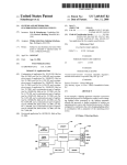
Simon Fraser University
8888 University Dr.
Burnaby, BC Canada
Email: [email protected]
October 08, 2012
Dr. Andrew Rawicz
School of Engineering Science
Simon Fraser University
Burnaby, British Columbia
V5A 1S6
Re: ENSC 440 Functional Specification for an Automated High Beam System
Dear Dr. Rawicz,
The attached document is the functional specification for Lumos Technologies’ Automated High
Beam System. The goal is to build a system that automatically dims a vehicle’s high beam headlights
by detecting nearby vehicles through real-time video processing. The purpose of this document is to
provide a set of high-level specifications of the functionality for our high beam system. Each section
will outline a specific type of requirement that should be met to have a successful product. This
document also contains test sequences to validate the hardware, software and overall system
functionality.
Lumos Technologies consists of five talented and motivated engineering students: Alex Huang,
Claire Liu, Linda Zhao, Sujin Lee, and Victor Mateescu. If you have any questions or concerns about
our proposal, please do not hesitate to contact me by phone at (778) 233-8586 or by e-mail at
[email protected]
Sincerely,
Linda Zhao
Chief Executive Officer
Lumos Technologies
Enclosure: Functional Specification for an Automated High-Beam System
Functional Specification
Automated High Beam System
Functional Specification for an Automated High Beam System
Linda Zhao
Chief Executive Officer
Sujin Lee
Chief Finance Officer
Victor Matesccu
VP Research & Development
Alex Huang
VP Software
Claire Liu
VP Operation
Contact Person:
Linda Zhao
[email protected]
Submitted To:
Dr. Andrew Rawicz– ENSC 440
Dr. Steve Whitmore– ENSC 305
School of Engineering Science
Simon Fraser University
Issued Date:
October 8, 2012
Functional Specification for an Automated High Beam System
Executive Summary
High-beam headlights are meant to assist drivers with a wider headlamp range to ensure safety
during night driving. However, the direction and range of the high beam can be hazardous to the
surrounding vehicles. In an effort to solve this problem, Lumos Technologies has come up with a
proactive solution to prevent dangerous situation like this from occurring.
The Automated High Beam System is designed to detect oncoming cars and help drivers toggle their
high beam headlights so that they don’t blind others on the road. Our system will use a camcorder
to record traffic. The live video will be processed through our car detection algorithm to determine
when a car enters the hazardous zone within the range of the driver’s high beams. Our system will
determine the distance of other vehicles, the intensity of surrounding light sources, and the overall
need of the high beam headlights. In addition, the user will always have the power to override the
system’s control. This product is designed to allow the driver to focus their attention on the road in
situations where active use of high beam headlights is desired.
The Lumos Technologies team has members who specialize in video processing, computer and
systems engineering, and electrical hardware development. We are committed to delivering a safe,
simple and easy to use solution that will improve the safety of everyone that share the road.
i
Functional Specification for an Automated High Beam System
Table of Contents
EXECUTIVE SUMMARY ................................................................................................................. I
LIST OF FIGURES ........................................................................................................................ III
GLOSSARY ................................................................................................................................. IV
1. INTRODUCTION........................................................................................................................1
1.1
SCOPE........................................................................................................................................ 1
1.2
INTENDED AUDIENCE .................................................................................................................... 1
1.3
DOCUMENT CONVENTIONS ............................................................................................................ 1
2. SYSTEM OVERVIEW ..................................................................................................................2
2.1
GENERAL REQUIREMENTS .............................................................................................................. 3
2.2
PHYSICAL REQUIREMENTS .............................................................................................................. 4
2.3
PERFORMANCE REQUIREMENTS ...................................................................................................... 4
2.4
MECHANICAL REQUIREMENTS......................................................................................................... 5
2.5
ELECTRICAL REQUIREMENTS ........................................................................................................... 5
2.6
ENVIRONMENTAL REQUIREMENTS ................................................................................................... 5
2.7
RELIABILITY REQUIREMENTS ........................................................................................................... 5
3. SOFTWARE...............................................................................................................................6
3.1
GENERAL REQUIREMENTS .............................................................................................................. 6
3.2
VEHICLE DETECTION REQUIREMENTS ................................................................................................ 6
3.3
VIDEO PROCESSING REQUIREMENTS................................................................................................. 7
3.4
IMAGE ACQUISITION REQUIREMENTS ............................................................................................... 7
4. HARDWARE .............................................................................................................................8
4.1 GENERAL REQUIREMENTS .................................................................................................................... 8
4.2 HIGH BEAM HEADLIGHT REQUIREMENTS ................................................................................................ 8
5. USER DOCUMENTATION ..........................................................................................................9
6. TEST PLAN.............................................................................................................................. 10
6.1
SOFTWARE TEST ........................................................................................................................ 10
6.2
HARDWARE TEST ....................................................................................................................... 10
6.3
SYSTEM INTEGRATION & USER ACCEPTANCE TEST............................................................................. 11
7. CONCLUSION ......................................................................................................................... 12
8. REFERENCES........................................................................................................................... 13
ii
Functional Specification for an Automated High Beam System
List of Figures
FIGURE 1 HIGH-LEVEL BLOCK DIAGRAM ................................................................................. 3
iii
Functional Specification for an Automated High Beam System
Glossary
CMVSS
HID
IEC
ISO
LED
WEEE
Canada Motor Vehicle Safety Standard
High intensity discharge lamp
International Electrotechnical Commission
International Organization for Standardization
Light emitting diode
Waste Electrical and Electronic Equipment
iv
Functional Specification for an Automated High Beam System
1. Introduction
The automated high beam system consists of a video camera mounted on the arm of the driver’s
rear view mirror. The live video from the video camera will be processed by a microprocessor to
detect any traffic in front of the driver. When a car is detected in the hazardous zone of the user’s
high beam headlights, the processor will turn off the high beams until the car has left the zone. The
system can only be activated after the user has already turned on the low beam headlights. The
processor output is wired to the car’s original headlights and the user is able to override this signal
whenever necessary. Once the automated system is enabled, the processor will control the high
beam bulbs of the headlights.
1.1 Scope
This document lists the functional specifications that Lumos Technologies will follow when
designing the automated high beam system. The document will describe the features of the system,
how it will perform, how it will interact with the user, and how we are planning to test the functions
mentioned. This document is not intended to describe the low-level implementation methods to
achieve the specifications listed.
1.2 Intended Audience
The functional specifications are targeted towards all members of the Lumos Technologies team.
The engineers will use this document as a guideline when developing each feature. Furthermore,
engineers will use the document in the final testing stages to ensure all outcomes adhere to our
original specifications. The upper level managers will be able to use this document to assess the
progress and success of the final product.
1.3 Document Conventions
The following convention will be used to indicate the type of function requirement:
[Rn-p] A functional requirement
where n is the requirement number and p is the priority of the requirement as follows:
I – Must be adhered to in the prototype.
II – Will be adhered to in the prototype if time permits.
III – Implementation is not planned for the prototype, but would be necessary for the production model.
1
Functional Specification for an Automated High Beam System
2. System Overview
The Automated High Beam System shall consist of a video camera, processing unit, control
electronics, and high beam lamps. The video camera will be mounted on vehicle’s windscreen to
provide input to the processing unit, which identifies vehicles and estimates their distances.
Decisions to dim or toggle the high beam will be made by the video processing system and will be
based on the estimated distance and the light intensity of the surroundings. The system will revert
the high beams to their original intensity when the high beam range is clear of other vehicles. The
driver will have three options to control high beam headlamps: “on”, “off”, and “auto”. The “on”
and “off” states will remain and function as any traditional headlamp controls. This will grant the
driver manual control over the headlamps, thus completely overriding our system.
A block diagram illustrating the mechanism of entire system is shown in Figure 1. When the system
is activated in the “auto” state, the video camera will constantly record the front view of driver’s
vehicle and send the information to the processing unit. This information will be analyzed to decide
when to open and close the switch. As soon as an oncoming vehicle is detected to be within range,
the video processor signals the high beam circuit to reduce the intensity of the headlamps. When
the range in front is clear of vehicles, the circuit restores the headlamp intensity.
The overall system requirements will be divided into four major sections, general requirements,
software requirements, hardware requirements, and user documentation requirements.
2
Functional Specification for an Automated High Beam System
Figure 1: High-Level Block Diagram
2.1 General Requirements
[R1-II]
[R2-II]
[R3-II]
[R4-III]
[R5-III]
[R6-III]
The system shall be compatible with all retail car models.
The system shall be user friendly and intuitive
The system must comply with the laws stated in the BC Motor Vehicle Act [1].
The retail price of the system should not exceed CAD$500.
The system shall be compatible with all retail vehicle models (i.e., cars, trucks,
motorcycles).
The system shall be installed by a qualified vehicle repair shop.
3
Functional Specification for an Automated High Beam System
2.2 Physical Requirements
[R7-I]
[R8-III]
[R9-III]
[R10-III]
[R11-III]
The system shall be activated with the push of a button and deactivated by
operating the existing automobile dip switch.
The system will not hinder the performance of any existing vehicle parts.
The camera will be mounted securely on the arm of the rear view mirror below the
windshield facing the front of the car.
All salient parts will be installed within the vehicle to minimize changes to the
vehicle’s appearance.
The wiring will not disturb the appearance of the vehicle’s interior.
2.3 Performance Requirements
[R12-I]
[R13-I]
[R14-I]
[R15-I]
[R16-I]
[R17-II]
[R18-II]
[R19-III]
[R20-III]
[R21-III]
The user will have the ability to manually override or disable the system.
When the system is turned on, the intensity of the high beams shall be set to the
standard maximum level.
The system shall function during hours of the night when there is no sunlight and
minimal street light.
The system shall detect cars up to a minimum of 100m in front and turn the high
beam lights off accordingly.
Manual override of the system shall occur instantaneously upon the user’s
command.
The system shall keep the high beam headlights off when the environment is
illuminated by other sources of light.
The system shall dim the high beam headlights by 50% when a car is detected
between 100m - 150m.
The system shall dim the high beam headlights by 25% when a car is detected
between 150m - 200m.
The system shall function during hours of partial darkness, such as dusk.
The system shall function under inclement weather, such as rain, snow and hail.
4
Functional Specification for an Automated High Beam System
2.4 Mechanical Requirements
[R22-I]
[R23-II]
The headlamp system must comply with Canada Motor Vehicle Safety Standard 108
(CMVSS 108) [2].
The installed product shall not interfere with the original mechanism of a vehicle’s
dip switch.
2.5 Electrical Requirements
[R24-I]
[R25-I]
[R26-III]
[R27-III]
The headlamp shall require no more than 12V, the camera no more than 12V, and
the processor no more than 5V.
The circuit must include car relays to minimize the current drawn by the headlight.
The system shall consume no more than 10W.
The system shall be power by the car battery.
2.6 Environmental Requirements
[R28-III]
[R29-III]
The system shall function between temperatures of -20ºC to 70ºC.
The system shall be Waste Electrical and Electronic Equipment (WEEE) compliant [3].
2.7 Reliability Requirements
[R30-I]
[R31-II]
[R32-II]
[R33-III]
The system wiring shall be fixable by any auto repair shop if wear and tear occurs.
The software shall determine vehicle distances from the input video within a 5%
margin of error.
The system shall not negatively affect the lifespan of the headlamp bulbs.
The system shall withstand breakage under normal usage.
5
Functional Specification for an Automated High Beam System
3. Software
The software application is composed of three individual sections with interrelated and distinct
functions. Vehicle Detection, Video Processing, and Image Acquisition are the three essential parts
of automated high beam system. The requirements under these subsections will specify the
necessary inputs to the system, the subsequent processing, and the outputs that will be provided to
the hardware component.
The Image Acquisition section will outline the specifications for the camera and input video feed.
The Video Processing component must be efficient and capable of operating in real-time. The
Vehicle detection section is responsible for making all the decisions to modify the high beam
intensity by analyzing the video input.
3.1 General Requirements
[R34-I]
[R35-I]
[R36-II]
[R37-II]
[R38-III]
[R39-III]
Software must operate in real time.
Software will operate in Linux.
Software development will use ISO/IEC 12207 [4].
Software development will use ISO/IEC 15504 [5].
The boot-up time of the software system shall be instantaneous when the user
activates auto mode for the high beams.
The response time between detecting a vehicle to switching the head light shall be
instantaneous.
3.2 Vehicle Detection Requirements
[R40-I]
[R41-I]
[R42-I]
[R43-I]
[R44-I]
Algorithm will estimate the distances from user’s car to other vehicles.
Vehicles will be tracked by their tail lights when facing the same direction as the
user.
Oncoming vehicles will be tracked by their headlamps.
Algorithm will be tailored specifically for night driving in sparsely lit areas, such as
highways.
Algorithm will be capable of detecting multiple cars at the same time and will adjust
the intensity of the high beams according to the distance of the closest car.
6
Functional Specification for an Automated High Beam System
[R45-I]
[R46-II]
Algorithm will detect any car within 100m and output a decision to adjust the high
beams.
Algorithm will detect any car within 150m and output a decision to adjust the high
beams.
3.3 Video Processing Requirements
[R47-I]
[R48-II]
Final implementation of the algorithm will be done in C/C++.
Each frame shall be processed in under 30ms.
3.4 Image Acquisition Requirements
[R49-I]
[R50-I]
[R51-I]
[R52-I]
Images will be captured at 30 frames per second.
Camera should not automatically adjust focus based on variation in light intensity.
The shutter speed and/or aperture of the camera shall be configured manually.
A static low exposure level shall be used to prevent artificial lights from appearing as
large saturated regions [6].
7
Functional Specification for an Automated High Beam System
4. Hardware
The hardware section will consist of a car battery, headlight, and other components. It will be
connected to a video processing subsystem as a source of input. The user will still have the basic
headlight dip switch control and our product will only add an external auto button. The hardware
section will be controlled by the processor’s output once the auto button is activated. The input
signal will control when to turn the high beam headlights on and off. This signal will be connected to
the headlights by a relay so the power source of the headlights is independent of the control signal
circuit.
4.1 General Requirements
[R53-I]
[R54-II]
[R55-II]
[R56-III]
[R57-III]
The system is activated when the user switches to auto mode.
A relay driver shall be connected between the video processing and headlight
systems.
The wires connecting between components shall be at least 12 gauges.
The system shall be powered by the vehicle’s built-in 12V battery.
All the connections shall be coated with insulating material to prevent corrosion.
4.2 High Beam Headlight Requirements
[R58-I]
[R59-II]
[R60-III]
The input for high beam bulb shall be 12V between 40W to 60W.
The system shall function with both individual and dual headlight bulb.
The system shall not function with LED and HID headlights.
8
Functional Specification for an Automated High Beam System
5. User Documentation
The user documentation package will be included with the production model only. It will include a
detailed documentation of how the system functions, intended for car manufacturers, as well as a
simple user's guide on how to operate the device.
[R61-III]
[R62-III]
[R63-III]
[R64-III]
[R65-III]
[R66-III]
[R67-III]
[R68-III]
The user documentation package shall include a user manual, installation
instructions, detailed circuit layout, specifications, data sheet, warranty, and contact
information for technical support.
The user technical manual shall be written for an audience with a strong technical
background on vehicle repair.
The user manual shall be written for an audience with minimal technical
background.
The user technical manual shall provide a detailed explanation on how to install the
system.
The user documentation shall emphasize operational and electrical safety
information.
The user manual shall consist of a brief, high-level overview and instructions on how
to operate the device.
The user manual shall describe the limitations of the device and summarize its
usability.
The user documentation package shall be provided in English, French, Spanish,
German, Traditional Chinese, Simplified Chinese, Japanese, and Korean for
international marketing purpose.
9
Functional Specification for an Automated High Beam System
6. Test Plan
6.1 Software Test
Software testing will be divided into two parts: unit testing on individual components of the
software system and performance and accuracy testing on the vehicle detection algorithm itself.
The former will mainly involve ensuring that the inputs and outputs of the software system are
functioning properly. The software will require a real-time, preferably uncompressed, video input.
This input can be tested simply by connecting the image acquisition device directly to a PC running
in a Linux environment and determining whether a stream of digital still frames can be transferred
in real-time onto the PC’s hard drive.
The vehicle detection algorithm will first be implemented in MATLAB for its convenience and ease
of use, to determine if it is accurate with only moderate consideration given to the processing time.
In the early stages of development, the algorithm will be fine-tuned using a set of simple test
sequences where the user’s car is stationary while only a single car drives in and out of range of the
user’s high beams. As progress is made, the algorithm will be tested on significantly more complex
input sequences taken from highway driving at night under a variety of different traffic conditions.
When the algorithm is proven to be effective, it will be re-implemented in C++ to allow real-time
functionality. Upon re-implementing it, we will match its output to that of the MATLAB
implementation to confirm that it functions identically.
6.2 Hardware Test
Prior to implementing our system in an actual vehicle, a standalone model of a car’s headlight
system will be built. To ensure all specifications have been properly implemented, the components
and sub-circuits will be tested individually. Headlight bulbs will first be substituted with an
appropriate load to allow us to verify the switch control portion of our system. A function generator
or a power supply can be used to test the hardware circuitry before connecting the processor. For
safety reasons, the circuit will be tested with a power supply first. Once the functionality of the
circuit has been verified, a car’s dip switch, headlights and batteries will be added to the system and
tested again.
10
Functional Specification for an Automated High Beam System
Once a circuit is constructed, every electrical component will be measured with digital multimeters
(DMM) to ensure that all voltage levels are correct and no power leakage occurs. Special
components, such as an automobile relay, will be specifically tested to ensure that a low input
voltage will switch on the headlights, which are powered separately by a car battery.
After the hardware circuit has been tested, we will integrate the processor’s output signal and
replace the function generator. Then, depending on time constraints, we will either implement our
system into a real passenger vehicle or simply attach an external set of headlights to the vehicle’s
hood.
6.3 System Integration & User Acceptance Test
In order to validate the functionality, performance, and reliability of the Automated High Beam System
once the hardware and software modules are combined, the system integration test will be done in
several stages. This approach has the advantage of allowing development and testing of each
component separately and concurrently. During each testing stage, the integrated system will be tested
for performance and reliability.
To ensure all the purchased components meet our specifications, we will verify the reliability, durability
and environmental requirements of the system. We will begin with testing the switch between on, off,
and auto mode to ensure the system is activated properly. Once this is confirmed to be correct, we will
check if the high beam headlights behave as we expect them to. This is done by sending binary signals to
the high beam headlights subsystem from the video processing subsystem, but without performing
actual video processing step. When the basic communication between hardware and software is
validated to work accordingly, we will run several different test cases to ensure all the corner cases are
accounted for and estimate the failure rate.
Once all of the testing is complete, we will do an overall check of each requirement, including
functionality, performance, and reliability. The final system integration check will ensure our prototype
device meets the requirements outlined in this document. Upon completing this last verification step,
the prototype device will be ready for the user acceptance test.
The user acceptance test will simply be to determine if the system can be operated intuitively by any
driver. Non-expert participants will be told to operate the controls to activated the Automated High
Beam system and manually override it at will. The purpose of this test is to simulate practical usage of
the device and to confirm that it meets our expectations.
11
Functional Specification for an Automated High Beam System
7. Conclusion
The specifications in this document describe the capabilities and functions of the Automated High Beam
system. We have outlined the criteria our product will adhere to, along with plans for the user
documentation, and a comprehensive description of our testing procedure. The prototype module will
meet the primary specifications (marked with either I or II) and will be completed by December 4th,
2012.
12
Functional Specification for an Automated High Beam System
8. References
*1+ BC Laws. (Jan. 2012). “Motor Vehicle Act Regulations” *Online+. Available:
http://www.bclaws.ca/EPLibraries/bclaws_new/document/ID/freeside/26_58_01. [Accessed Sept
16, 2012].
[2+ Canada Motor Vehicle Safety Standards (CMVSS). (Feb. 2012). “Motor Vehicle Safety Regulations
(C.R.C., c. 1038)” *Online+. Available: http://www.tc.gc.ca/eng/acts-regulations/regulations-crcc1038.htm [Accessed Sept 25, 2012].
[3+ Waste Electrical and Electronic Equipment (WEEE). (Sept. 2012). “Recast of the WEEE Directive”
[Online]. Available: http://ec.europa.eu/environment/waste/weee/index_en.htm [Accessed Oct,
6th, 2012].
[4] ISO/IEC 15504-1:2004. (Oct 2011). INTERNATIONAL STANDAR. [Online]. Available:
http://webstore.iec.ch/preview/info_isoiec15504-1%7Bed1.0%7Den.pdf [Accessed Sept 25, 2012].
[5] ISO/IEC 12207:2008. (Oct 2011). INTERNATIONAL STANDAR. [Online]. Available:
http://webstore.iec.ch/preview/info_isoiec12207%7Bed2.0%7Den.pdf [Accessed Sept 25, 2012].
[6] R. O'Malley, E. Jones, M. Glavin, "Rear-Lamp Vehicle Detection and Tracking in Low-Exposure
Color Video for Night Conditions," IEEE Trans. Intelligent Transportation Systems, vol. 11, no. 2, pp.
453-462, June 2010.
13