1
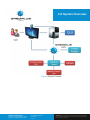
T. 1-778-990-7688 Larry Zhao F. 1-778-385-0432 Chief Executive Officer Support 1-778-388-3751 [email protected] October 11, 2011 Andrew Rawicz School of Engineering Science Simon Fraser University Burnaby, B.C. V5A 1S6 Re: ENSC 440, functional specifications: Display Augmentation System Dear Dr. Rawicz: The attached document describes the functional specifications related to our Display Augmentation System, a product of Daedalus Technologies. Our product is designed with both innovation and robustness in mind. Not only are we aiming to provide potential end users with increased comfort and convenience in front of a visual display unit, but also providing the user with an ideal ergonomic view to help reduce the likelihood of strain related injuries. The attached functional specifications provide requirements for Display Augmentation System’s functionality in development and production phases. These specifications were generated after careful analysis of all factors involved in this field. The business and engineering teams at Daedalus Technologies are using this documentation for research and development in addition to ensuring that the project stays on course. Daedalus Technologies is founded by fifth year Engineering Science students: Larry Zhao, Ian Brown, Calvin Ho, and Jordan Anguelov. Should you have any questions or concerns regarding our project proposal, please feel free to contact me by phone at (778) 990-7688, by e-mail at [email protected] or at [email protected]. Sincerely, Larry Zhao Chief Executive Officer Daedalus Technologies Enclosure: Functional Specification for Display Augmentation System Daedalus Technologies Since 2011 Electronics •PCB •Ergonomics •Design [email protected] 8888 Unversity Drive •V5A 1S6 Burnaby B.C. | CA D isclaimer THIS DOCUMENT CONTAINS INFORMATION THAT IS PROPRIETARY TO THE DAEDALUS TECHNOLOGIES. NO PART OF THIS DOCUMENT MAY BE DUPLICATED OR USED FOR COMMERCIAL PURPOSES WITHOUT THE PRIOR CONSENT OF THE OWNER. Functional Specification Display Augmentation System Prepared for: Andrew Rawicz (ENSC 440) Mike Sjoerdsma (ENSC 305) Simon Fraswer University Simon Fraswer University School of Engineering Science School of Engineering Science Prepared by: Larry Zhao Chief Executive Offier Ian Brown VP Finance Date: October 13, 2011 Revision: 1.0 Jordan Anguelov VP Hardware Calvin Ho VP Software Executive Summary Unwanted neck or back strains? Eye redness when spending long periods of time in front of a monitor? As of March 31, 2011 almost two billion people use computers to access the internet. This is a net growth of 480.4% since the year 2000 [1]. While humanity is becoming more and more reliant on computers, issues associated with them are not getting properly addressed. Injuries such as Asthenopia, Repetitive Strain Injury, Photophobia, and Presbyopia are a seriously concern to users who are heavily dependent on computer functions. Whether it is at work or at home, reliance on computing devices is a growing trend in the 21st century. Here at Daedalus Technologies, we feel that our Display Augmentation System (DAS) can address these health issues by reducing the strain on a user’s neck and eyes. The purpose of DAS is to help keep users’ in an optimal view position while providing visual feedback about the process. The basis of the system is a software application to track users’ locations and send information to the external microcontroller; the microcontroller then drives the motorized system to move the Visual Display Unit (VDU) according to the users’ movements. The development of DAS will occur in two phases. In the first phase, a proof of concept model will be developed to verify core functionality. In the second phase, the proof of concept model will be developed further into a prototype which shall become the basis for our base production model. The first phase of development is targeted for completion by December of 2011 and will focus on the following core features needed for basic functionality: • Facial recognition, GUI and image processing. • A working Printed Circuit Board (PCB) that houses a microcontroller and support for motor controls. • A mechanical prototype that supports a flat panel display monitor and moves it in 2 axes. • A GUI that acts as HUD and provide feedback from the hardware and software modules. In addition to the functional requirements listed above, safety and reliability are of the utmost importance to our team at Daedalus Technologies; numerous standards (RoHS, CSA, ISO, etc.) will be adhered to and a rigorous test plan will be developed and executed to ensure a product that is secure, dynamic and reliable. The final product or second phase of development will build upon the successes from the first phase; therefore, the timeline and milestone will be determined after the completion of the first phase. This document details the functional specifications for the first phase and partially for the second phase of development. The details discussed for the second phase are only preliminary and subject to change as further research is needed. Daedalus Technology Executive Summary 8888 Unversity Drive • Burnaby B.C. V5A 1S6 Confidential Page • ii D isclaimer THIS DOCUMENT CONTAINS INFORMATION THAT IS PROPRIETARY TO THE DAEDALUS TECHNOLOGIES. NO PART OF THIS DOCUMENT MAY BE DUPLICATED OR USED FOR COMMERCIAL PURPOSES WITHOUT THE PRIOR CONSENT OF THE OWNER. Table of Contents Executive Summary List of Figures Glossary 1.0 Introduction 1.1 Scope 1.2 Intented Audience 1.3 Document Conventions 2.0 System Overview 2.1 General Requirements 2.2 Physical Requirements 2.3 Performance Requirements 2.4 Environmental Requirements 2.5 Mechanical Requirements 2.6 Electrical Requirements 2.7 Reliability Requirements 3.0 Software 3.1 General Requirements 3.2 Face Tracking Requirements 3.3 GUI Requirements 3.4 Image Acquisition Requirements 4.0 Support Stand 5.0 User Documentation 6.0 Test Plan 6.1 Hardware Test 6.2 Software Tests 6.3 System Integration Test 6.4 User Acceptance Test Conclusion References ii iv v 1 1 1 1 2 3 3 3 4 4 4 5 6 6 6 7 7 8 8 9 9 10 10 11 12 13 Table of Content Daedalus Technology Table of Content 8888 Unversity Drive • Burnaby B.C. V5A 1S6 Confidential Page • iii D isclaimer THIS DOCUMENT CONTAINS INFORMATION THAT IS PROPRIETARY TO THE DAEDALUS TECHNOLOGIES. NO PART OF THIS DOCUMENT MAY BE DUPLICATED OR USED FOR COMMERCIAL PURPOSES WITHOUT THE PRIOR CONSENT OF THE OWNER. Figure 1 System Overiew List of Figures 3 List of Figures Daedalus Technology List of Figures 8888 Unversity Drive • Burnaby B.C. V5A 1S6 Confidential Page • iv D isclaimer THIS DOCUMENT CONTAINS INFORMATION THAT IS PROPRIETARY TO THE DAEDALUS TECHNOLOGIES. NO PART OF THIS DOCUMENT MAY BE DUPLICATED OR USED FOR COMMERCIAL PURPOSES WITHOUT THE PRIOR CONSENT OF THE OWNER. Glossary ANSI: American National Standards Institute BDC: Brushed Direct Current CSA: Canadian Standard Association DAS: Display Augmentation system EMC: Electromagnetic Compatibility GUI: Graphical User Interface HUD: Heads-Up Display IEC: International Electrotechnical Committee ISO: International Organization of Standardization LED: Light Emitting Diode MIS: Mounting Interface Standard MTBF: Mean Time Between Failures MTF: Mean time to Failure PC: Personal Computer PCB: Printed Circuit Board RoHS: Restriction of Hazardous Substances Directive RS-232: Recommended Standard 232 UAT: User Acceptance Test USB: Universal Serial Bus Daedalus Technology Glossary 8888 Unversity Drive • Burnaby B.C. V5A 1S6 Confidential Page • v D isclaimer THIS DOCUMENT CONTAINS INFORMATION THAT IS PROPRIETARY TO THE DAEDALUS TECHNOLOGIES. NO PART OF THIS DOCUMENT MAY BE DUPLICATED OR USED FOR COMMERCIAL PURPOSES WITHOUT THE PRIOR CONSENT OF THE OWNER. 1.0 Introduction Daedalus Technologies’ DAS is designed to create a more comfortable environment for heavy computer users while it auto adjusts the VDU position to better suit the user’s needs. As well as providing visual feedback to keep the users in an optimal ergonomic view position. This document outlines in detail the functional specifications for DAS. 1.1 Scope This document provides the functional requirements for Daedalus Technologies’ DAS. The specifications describe the proof of concept model, prototype and production model. Daedalus Technologies will closely follow the proceeding requirements throughout the entire development phase. Figure 1.2 Intented Audience These listed specifications are intended for use by the members of Daedalus Technologies. The document will serve as a baseline through all project development phases. Software and Hardware Vice Presidents (VPs) are to refer to the set of requirements to assist them in completing the project milestones, and the project manager will use it to provide feedback and counsel on the team’s progress. All software, hardware, system integration and user acceptance testing will consider these requirements as the guideline for quality assurance. 1.3 Document Conventions In order to indicate the type of functional requirement the following convention will be used: [Rn-p] A functional requirement where n is the requirement number, and p is the requirement’s priority with one of the three values: I - First priority; must be adhered to in proof of concept model and needed in prototype and production model unless otherwise stated. II - Second priority; will be adhered to in prototype and production model but only in proof of concept if time permits. III - Third priority; completion not planned for proof of concept, but would be necessary for the production model. Daedalus Technologies 1.0 Introduction Electronics •PCB •Ergonomics •Design [email protected] Confidential Page • 1 D isclaimer THIS DOCUMENT CONTAINS INFORMATION THAT IS PROPRIETARY TO THE DAEDALUS TECHNOLOGIES. NO PART OF THIS DOCUMENT MAY BE DUPLICATED OR USED FOR COMMERCIAL PURPOSES WITHOUT THE PRIOR CONSENT OF THE OWNER. 2.0 System Overview The system shall consist of a platform, stand, nacelle, control electronics, webcam and Graphical User Interface (GUI). The system will have two degrees of freedom in which the monitor will be allowed to move. By using a Video Electronics Standards Association (VESA) mounting plate, we will be able to use any VDU that complies with the VESA mounting standard [2]. The microcontroller will interface with a host computer via a serial communications link. The system will track the user’s face and adjust the mounted VDU to keep it in its target location. The system consists of several blocks. The first is the mechanical block; it is the backbone of the system, holding the motors and the VESA mount as well as housing all the electronics. The second block is the electronics block; the electronics consist of a power supply, microcontroller and motor control circuitry. The electronics are responsible for controlling the position of the motors, calculating user distance from screen, controlling the status Light Emitting Diodes (LED) and communicating with the host Personal Computer (PC). The final block is the software application running on the host PC; the software on the GUI is responsible tracking users, calculating the relative user position to the center of the screen and relaying the data to the microcontroller over a serial port. A simplfied diagram shown in figure 1 shows the general overiew of our system. The overall system requirements will be divided into four major categories, general system requirements, software requirements, support stand requirements, and user documentation requirements. Daedalus Technologies 2.0 System Overview Electronics •PCB •Ergonomics •Design [email protected] Confidential Page • 2 D isclaimer THIS DOCUMENT CONTAINS INFORMATION THAT IS PROPRIETARY TO THE DAEDALUS TECHNOLOGIES. NO PART OF THIS DOCUMENT MAY BE DUPLICATED OR USED FOR COMMERCIAL PURPOSES WITHOUT THE PRIOR CONSENT OF THE OWNER. 2.0 System Overview Figure 1 System Overiew Daedalus Technologies 2.0 System Overview Electronics •PCB •Ergonomics •Design [email protected] Confidential Page • 3 D isclaimer THIS DOCUMENT CONTAINS INFORMATION THAT IS PROPRIETARY TO THE DAEDALUS TECHNOLOGIES. NO PART OF THIS DOCUMENT MAY BE DUPLICATED OR USED FOR COMMERCIAL PURPOSES WITHOUT THE PRIOR CONSENT OF THE OWNER. 2.0 System Overview 2.1 General Requirements [R1-I] The system must be relatively cheap with retail cost no greater than $50. [R2-I] The system must be used with monitors compatible with the VESA MIS- D/MIS-E and MIS-F mounting standards[3]. [R3-III] The system must work with any USB 2.0 compatible webcam. [R4-II] The GUI of the system shall be simple and aesthetic to ensure a smooth user experience. [R5-I] System shall not be water resistant 2.2 Physical Requirements [R6-I] The system must be compact enough to be placed on a desk. [R7-I] DAS shall be aesthetically pleasing. [R8-I] Overall dimensions that will not exceed the largest possible computer monitor. [R9-III] Dimension and weight of the overall system varies in the final product due to different sizes of VDUs. [R10-I] Proximity sensor shall be mounted facing the user. [R11-III] The system shall have a LED backlights. [R12-I] The proof of concept structure shall be made from steel and aluminum. [R13-I] The product shall not have any sharp edges that my cause injury to a user/operator. 2.3 Performance Requirements [R14-I] [R15-I] [R16-III] [R17-I] [R18-I] [R19-I] [R20-I] [R21-III] [R22-III] [R23-I] [R24-III] [R25-II] [R26-III] [R27-I ] The system must detect the face of at least one person within the cam- era field of view. The system must keep the flat panel monitor centered on the user’s face. The system will be upgradable to accommodating multiple axes of movement and rotation. Upon powering on, the system will be centered at a predefined origin. System will include a multicolour LED to indicate status. Red illuminated LED means system is on but not connected. Green illuminated LED indicates system is working normally. Flashing red light means system fault. Flashing green light means motor fault. The system must be used in enough light to obtain a reasonable image capture for facial recognition DAS will be offered in various temperature ranges such as commercial, industrial and extended (military). If the captured image quality is too low then a warning will appear. If the captured image quality is too low, the option to automatically ad- just the LED lighting will be given. System response must be in real time. Daedalus Technologies 2.0 System Overview Electronics •PCB •Ergonomics •Design [email protected] Confidential Page • 4 D isclaimer THIS DOCUMENT CONTAINS INFORMATION THAT IS PROPRIETARY TO THE DAEDALUS TECHNOLOGIES. NO PART OF THIS DOCUMENT MAY BE DUPLICATED OR USED FOR COMMERCIAL PURPOSES WITHOUT THE PRIOR CONSENT OF THE OWNER. 2.0 System Overview Figure 2.4 Environmental Requirements [R28-I] [R29-I] [R30-II] [R31-III] (RoHS) [R32-III] The product shall be quiet i.e. motors should not be noticeable. Audible system noise should not exceed 50dB[4]. The system will operate from 0 - 50 °C and humidity of 50%. The device shall be Restriction of Hazardous Substances Directive compliant [5]. In compliance to Waste Electrical and Electronic Equipment (WEEE) [6],a recycling program will be implemented to collect and/or replace the de vice component(s) at the end of the life cycle. Figure 2.5 Mechanical Requirements [R33-I] The proof of concept model and production model shall include a VESA compatible mounting bracket. [R34-I] The shaft shall be hollow enough to accommodate the PCB and electron- ics inside. [R35-I] The proof of concept model must include up and down tilt of +40 to -20 degrees. [R36-I] The proof of concept model must include left and right rotation of +/- 90 degrees. [R37-III] The final product will consist of mostly plastic structure with the exception of critical areas. [R38-III] The final product will have a unique system for mounting the webcam and proximity sensor. [R39-II] The proof of concept model shall be strong enough to support a load of 10kg, more than most modern flat panel displays. [R40-III] The final product should support more than 20kg to support various types of VDUs. [R41-I] Nacelle will accommodate a linear actuator for tilt. Figure 2.6 Electrical Requirements [R42-I] Both proof of concept and production models must use an external power supply. [R43-I] Power supply must be rated for 12V at 1A and must have safety certifica- tion by standard agency such as CSA, UL, EC etc[7]. [R44-I] Power supply must be galvanically isolated to ensure user safety in case of short circuit. [R45-I] The system must have a power switch at the 12V input to turn the system on/off. [R46-I] The proof of concept model must have 2 Brushed Direct Current (BDC) motors for movement, 1 for rotation and 1 for tilt. Daedalus Technologies 2.0 System Overview Electronics •PCB •Ergonomics •Design [email protected] Confidential Page • 5 D isclaimer THIS DOCUMENT CONTAINS INFORMATION THAT IS PROPRIETARY TO THE DAEDALUS TECHNOLOGIES. NO PART OF THIS DOCUMENT MAY BE DUPLICATED OR USED FOR COMMERCIAL PURPOSES WITHOUT THE PRIOR CONSENT OF THE OWNER. 2.0 System Overview [R47-I] The two BDC motors must be driven by an H-bridge, the H-bridge allows for forward and reverse control. [R48-I] The proof of concept model shall be based on an elementary microcon troller to control peripheral devices. [R49-I] The system will interface with a host PC via RS-232 compliant serial port [8]. [R50-I] The system will have an IR proximity sensor to detect distance of user relative to the screen, the proximity sensor shall have a range of 0-1.5 meters. [R51-I] The PCB must be ANSI / IPC-2221/IPC-2221A compatible to ensure ap propriate trace width and creepage clearance[9]. [R52-I] The product shall only use commercial temperature grade components (0 °C to 70 °C) [10]. [R53-III] The final product would be based on a more complex processor. [R54-III] The final product should have USB 2.0 port and act like a USB device for interaction. [R55-III] The final product shall meet and/or exceed class A and B Electromag- netic Compatibility (EMC) standards [11]. [R56-III] The system shall have an output for controlling a LED string serving as an aesthetic backlight for the monitor. [R57-I] The PCB shall be slim enough to fit inside the base shaft. [R58-I] The system shall consume no more than 10 watts, so that the system remains energy efficient. [R59-I] The system operating frequency shall be no more than 20MHz. [R60-I] The input power will be filtered to remove any noise from the input adapt- er and from the motors. Figure 2.7 Reliability Requirements [R61-II] The system will have no exposed electrical wires or circuit components. [R62-II] The stand shall be properly rooted when a VDU is mounted, i.e. device must not be able to be tipped on its side without the use of excessive force. [R63-I] The system will have a smooth outer case to prevent personal injury. [R64-I] The system will be able to be disassembled for servicing and repairing without damaging any components. [R65-III] Mean time to Failure (MTF) of the mechanical structure shall be greater than 150,000 hours. [R66-III] MTF of electrical components will be greater than 100,000 hours. [R67-III] Mean Time Between Failures (MTBF) of system shall be greater than 100,000 hours. [R68-III] MTF of power adapter will be 100,000 hours [12]. Daedalus Technologies 2.0 System Overview Electronics •PCB •Ergonomics •Design [email protected] Confidential Page • 6 D isclaimer THIS DOCUMENT CONTAINS INFORMATION THAT IS PROPRIETARY TO THE DAEDALUS TECHNOLOGIES. NO PART OF THIS DOCUMENT MAY BE DUPLICATED OR USED FOR COMMERCIAL PURPOSES WITHOUT THE PRIOR CONSENT OF THE OWNER. 3.0 Software The Software application consists of three distinct sections with their own required functions; Face tracking, GUI, and Image Acquisition are the three integral parts of the DAS application. These three sets of standards will ensure that the user experience is smooth and intuitive as each user will have a different preference for monitor functionality. The Face Tracking section must be accurate enough to detect user’s movement, but not overly sensitive as to track unnecessary objects. The GUI section will be the users’ primary input for the DAS application. It will be functional to the point where the user can eventually control all the settings of a completed DAS within safe limits. The Image Acquisition section will be the main input to the DAS application. It will be responsible for accessing the webcam and managing correct webcam settings. Image capture will be snappy and allow for all other software requirements to be met accurately. 3.1 General Requirements [R69-I] Our application will be stable and not directly interfere with normal computer processes. [R70-I] Our application will be comprised of three well-defined modules to allow for optimal efficiency. [R71-II] Software development will use ISO/IEC 12207 [13]. [R72-II] Software development will use ISO/IEC 15504 [14]. [R73-III] The program will be bundled into a single, stable, executable application. 3.2 Face Tracking Requirements [R74-I] Algorithm will detect any face in view. [R75-I] The most easily recognizable face will be tracked first. [R76-I] Sudden and drastic changes in face location will be ignored. [R77-I] When multiple faces are detected, the monitor will be centered until user defined cases are identified. [R78-II] Users can define how multiple faces are handled. [R79-II] Distance feedback will be added into face tracking. [R80-III] Users will be able to control the sensitivity of the system with operational limits. [R81-III] Users can choose what faces to follow and ignore. Daedalus Technologies 3.0 Software Electronics •PCB •Ergonomics •Design [email protected] Confidential Page • 7 D isclaimer THIS DOCUMENT CONTAINS INFORMATION THAT IS PROPRIETARY TO THE DAEDALUS TECHNOLOGIES. NO PART OF THIS DOCUMENT MAY BE DUPLICATED OR USED FOR COMMERCIAL PURPOSES WITHOUT THE PRIOR CONSENT OF THE OWNER. 3.0 Software Figure 3.3 GUI Requirements [R82-I] The GUI will display the currently processing image. [R83-I] The GUI can calibrate target face position. [R84-I] The GUI has start and stop buttons. [R85-I] The GUI has buttons to move monitor position. [R86-I] The GUI and image shown will be a fixed size. [R87-II] The GUI displays face positional data below the captured image. [R88-II] The GUI highlights faces on processed image. [R89-II] The GUI has a default position which can be changed via calibrated settings. [R90-II] The GUI “default position” button shall be operational. [R91-III] The GUI displays face positional data on the highlighted rectangle itself. [R92-III] The GUI can control the lighting strip. [R93-III] The GUI can select COM port of webcam. [R94-III] The GUI can show COM port status. [R95-III] The GUI can select faces to follow. [R96-III] The GUI will have advanced user tabs for added functionality and customization. [R97-III] The GUI automatically detects webcam type and has a list of other formats available in the advanced settings tab. Figure 3.4 Image Acquisition Requirements [R98-I] Software will work with select webcams initially. [R99-I] Images will be captured at a minimum 2 frames per second by the GUI. [R100-II] A proximity sensor will assist in image acquisition. [R101-III] Software will support a variety of webcams. [R102-II] The system will be able to turn off the monitor when no user is detected for a predefined amount of time in order to save power and reduce energy consumption. [R103-III] Image capture will be set to a value appropriate for system response time or user defined. Daedalus Technologies 3.0 Software Electronics •PCB •Ergonomics •Design [email protected] Confidential Page • 8 D isclaimer THIS DOCUMENT CONTAINS INFORMATION THAT IS PROPRIETARY TO THE DAEDALUS TECHNOLOGIES. NO PART OF THIS DOCUMENT MAY BE DUPLICATED OR USED FOR COMMERCIAL PURPOSES WITHOUT THE PRIOR CONSENT OF THE OWNER. 4.0 Support Stand The support stand will be constructed personally by the engineers at Daedalus Technologies to ensure the proof of concept model and production model is durable and ascetically pleasing. [R104-I] 1.1 Scope [R105-I] [R106-I] [R107-I] [R108-II] [R109-II] [R110-II] Physical dimensions shall not exceed 65mm wide 300mm tall. Total stand and support base weight shall be no more than 10kg, the proof of concept would be a little more due to heavier materials used. The stand shall be durable and resistant to cracks or breakage. VESA mount plate shall be 210mm x 210mm in order to accommodate MIS standards [15]. The orientation of the buttons shall be user-friendly. The stand shall be constructed for optimal stability. The stand shall not be water proof. 5.0 User Documentation The user documentation will be written for the production model only. It must be concise, straight-forward, and target the general public. The documentation also must be easy to understand with no ambiguity in its instructions. [R111-III] Device will include a quick start guide. [R112-III] The user documentation shall be written to an audience with minimal technical background. [R113-III] The documentation shall include a user manual. [R114-III] Detailed technical information for product assembly shall be included. [R115-III] The user manual must have clear and precise operating instructions. [R116-III] User documentation shall include pictures and wording to aid in describing product features. [R117-III] The user documentation shall be translated into multiple languages. [R118-III] The user documentation shall include operational and electrical safety information. [R119-III] User documentation will contain warranty details. [R120-III] User documentation will provide instructions for all functionalities relevant to software GUI. [R121-III] User documentation will outline the usability and limitations of the device. [R122-III] The user documentation shall contain corporate address, website and contact information for complains, feedback, general inquires as well as investment opportunities. Daedalus Technologies 5.0 User Documentation Electronics •PCB •Ergonomics •Design [email protected] Confidential Page • 9 D isclaimer THIS DOCUMENT CONTAINS INFORMATION THAT IS PROPRIETARY TO THE DAEDALUS TECHNOLOGIES. NO PART OF THIS DOCUMENT MAY BE DUPLICATED OR USED FOR COMMERCIAL PURPOSES WITHOUT THE PRIOR CONSENT OF THE OWNER. 6.0 Test Plan For a product that is unique, innovative and has no market presence, we feel the testing phase is paramount in our project development. To ensure that our product is properly engineered, a replica of what our team at Daedalus Technologies envisioned will be prototyped and tested. We have taken drastic measures to draft a comprehensive test plan to comply with this standard. In this section, the overall test plan for DAS will be discussed. Since the project team has been divided separately for its hardware and software components, the system’s hardware and software will be tested separately. System integration test will commence once hardware and software modules have passed their respective tests. To ensure potential end user satisfaction, we decided to include a user acceptance test at the very end of DAS’s project development cycle. Figure 6.1 Hardware Test Support Stand Test Testing will validate the manufactured stand’s durability and reliability. This will be done through a combination of usability testing, stress testing, drop testing, and blunt force testing. The results of this test will directly impact our systems ability to handle the full range of physical tests and is therefore very important to pass. Motor Tests By increasing the mass attached to the motors, we can observe the motors performance over various loads. We will also test the motors for extended periods of time. By running the motor for an extended period of time and checking temperature levels, we can determine maximum run times and establish safety limits. Individual motors will also be tested separately to determine that they meet the requirements and standards. PCB tests The PCB (Arduino shield) will be subject to several tests to evaluate the performance of the on board circuitry. When the PCB is built, the first component to be integrated will be the power supply. The PCB will then be powered and checked for short circuits. The buck converter will be tested for accuracy under various loads from 0-2 Amps by adding a load resistor of appropriate size. The RS-232 transceiver will be checked for the correct voltage levels with an oscilloscope. Daedalus Technologies 6.0 Test Plan Electronics •PCB •Ergonomics •Design [email protected] Confidential Page • 10 D isclaimer THIS DOCUMENT CONTAINS INFORMATION THAT IS PROPRIETARY TO THE DAEDALUS TECHNOLOGIES. NO PART OF THIS DOCUMENT MAY BE DUPLICATED OR USED FOR COMMERCIAL PURPOSES WITHOUT THE PRIOR CONSENT OF THE OWNER. 6.0 Test Plan Figure 6.2 Software Tests Unit testing will be performed on each software module before Image Acquisition, GUI and Face Tracking are integrated into a completed application. During each stage, meticulous performance and reliability testing will ensure that corner cases are covered and accounted for. This way we can ensure that bugs and defects have minimal consequences during system integration. The general software test plan will consist of basic functionality tests while increasing the computational demands of the system. We will then move toward feeding modules false or bad data to ensure that error handling is intact to avoid problems with the program once connected to the hardware. It will be important to create a variety of test procedures once the GUI is completed to check that simultaneous entries do not cause unexpected errors at varying frames per second. This will have to be tested again once feedback from the hardware has been included. Before a commercial release, we would have to check that our application does not interfere or fail because of other computer processes being run concurrently Figure 6.3 System Integration Test The purpose of system integration test is to verify functional, performance, and reliability requirements[16] once hardware and software modules are combined. All the specified dimensions will be accurately measured; all the safety requirements will be met by over designing the system; and all the safety components present during the entire development stage of the project. Ensuring that all purchased components meet our specifications, we will also verify the reliability, durability and environmental requirements of the system. Once assembled, the chassis will be subject to weight loads in excess of ten kilogram attached to the VESA plate in order to verify stability and operational integrity. We will also run a series of failover consisting of cases when one or more modules go offline[17]. Once the completed hardware system has been tested, further testing with the fully integrated application is the last step. From that point on, we will introduce predefined communication errors based on the final design. These fabricated errors will be used to simulate noise and error in the system well beyond normal operating parameters to ensure the system’s robustness is superior than that of the normal wear and tear of an advanced user. This will be a very effective final system integration test because the hardware and software systems are connected by RS-232 alone. By testing the limits of our systems stability, we will be well on our way to completing a stable, reliable and competitive commercial product. Daedalus Technologies 6.0 Test Plan Electronics •PCB •Ergonomics •Design [email protected] Confidential Page • 11 D isclaimer THIS DOCUMENT CONTAINS INFORMATION THAT IS PROPRIETARY TO THE DAEDALUS TECHNOLOGIES. NO PART OF THIS DOCUMENT MAY BE DUPLICATED OR USED FOR COMMERCIAL PURPOSES WITHOUT THE PRIOR CONSENT OF THE OWNER. 6.0 Test Plan Once all of the testing is complete, we will do an overall check of every requirement. This will consist of going through each requirement individually to test its functionality, performance, and reliability. This final system integration check will act as the last step to ensure everything meets the requirements outlined in this document. This last verification step will act as an indication that our project is ready for the user acceptance testing. Figure 6.4 User Acceptance Test The goal of user acceptance test is a final verification procedure to determine if the requirements of a product specification are met. By emulating real-world usage conditions on behalf of end users, UAT will carry out with external candidates outside of Daedalus Technologies. The candidate will be instructed to run through some basic test cases involving our prototype. The results of these tests give confidence to end users in how our product will perform and give Daedalus Technologies important user feedback. UATs are needed because DAS is a unique and innovative product that the consumer market has yet to witness. As a result, expectation and suggestions will take into account for Daedalus Technologies to progress into the second phase of this project. Daedalus Technologies 6.0 Test Plan Electronics •PCB •Ergonomics •Design [email protected] Confidential Page • 12 D isclaimer THIS DOCUMENT CONTAINS INFORMATION THAT IS PROPRIETARY TO THE DAEDALUS TECHNOLOGIES. NO PART OF THIS DOCUMENT MAY BE DUPLICATED OR USED FOR COMMERCIAL PURPOSES WITHOUT THE PRIOR CONSENT OF THE OWNER. Conclusion By carefully investigating the requirements for DAS’s overall system and sub-components, we will be able to proceed on our project with increased objective clarity. The Daedalus Technologies functional specification document outlines the general system, software and support stand requirement of the product in addiction to user documentation. Test plans are also outlined in this documentation. The proof-of-concept model is expected to meet the functional requirements outlined in this document marked with either I or II by December 6, 2011. Daedalus Technologies Conclusion Electronics •PCB •Ergonomics •Design [email protected] Confidential Page • 13 D isclaimer THIS DOCUMENT CONTAINS INFORMATION THAT IS PROPRIETARY TO THE DAEDALUS TECHNOLOGIES. NO PART OF THIS DOCUMENT MAY BE DUPLICATED OR USED FOR COMMERCIAL PURPOSES WITHOUT THE PRIOR CONSENT OF THE OWNER. References [1] Internet World Stats.(Oct 2011). Internet Users in the World Distributed by World Regions-2011. [Online]. Available: http://www.internetworldstats.com/stats.htm [2] Ergo in Demand.(Oct 2011). VESA Mount for LCD Monitors, LCD Displays and Plasma Screens. [Online]. Available: http://www.ergoindemand.com/about_VESA_ standard.htm [3] Wikipedia, the free encyclopedia. (Oct 2011). Flat Display Mounting Interface. [Online]. Available: http://en.wikipedia.org/wiki/Flat_Display_Mounting_Interface [4] Usniversity Safty Office. (Oct 2011). The Noise at Work Regulations 2005. [Online]. Available: http://www.admin.ox.ac.uk/safety/policy-statements/s1-06/#d.en.21490 [5] “RoHS Compliance.” [Online]. Available: http://www.rohs.eu/english/index.html [6] “Waste Electrical and Electronic Equipment (WEEE).” [Online]. Available: http: //ec.europa.eu/environment/waste/weee/index_en.htm [7] UL. (Oct 2011). Power Supplies. [Online]. Available: http://www.ul.com/global/eng/ pages/offerings/industries/hightech/powersupplies/ [8] Lammertbies.(Oct 2011). RS232 Specifications and standard. [Online]. Available: http://www.lammertbies.nl/comm/info/RS-232_specs.html [9] Wikipedia, the free encyclopedia. (Oct 2011). Electromagnetic compatibility. [Online]. Available:http://en.wikipedia.org/wiki/Electromagnetic_compatibility] [10] Wikipedia, the free encyclopedia. (Oct 2011). Operating temperature. [Online]. Available: http://en.wikipedia.org/wiki/Operating_temperature [11] APTA SS-E-010-98. (Oct 2011). Standard for the Development of an Electromagnetic Compatibility Plan. [Online]. Available: http://www.aptastandards. com/portals/0/PRESS_pdfs/Electric/elec%20reaffirm/SS-E-010-98%20Development%20of%20an%20Electromagnetic%20Compatability%20Plan.pdf [12] Wikipedia, the free encyclopedia. (Oct 2011). Power supply unit. [Online]. Available: http://en.wikipedia.org/wiki/Power_supply_unit_%28computer%29 [13] ISO/IEC 15504-1:2004. (Oct 2011). INTERNATIONAL STANDAR. [Online]. Available: http://webstore.iec.ch/preview/info_isoiec15504-1%7Bed1.0%7Den.pdf Daedalus Technologies References Electronics •PCB •Ergonomics •Design [email protected] Confidential Page • 14 D isclaimer THIS DOCUMENT CONTAINS INFORMATION THAT IS PROPRIETARY TO THE DAEDALUS TECHNOLOGIES. NO PART OF THIS DOCUMENT MAY BE DUPLICATED OR USED FOR COMMERCIAL PURPOSES WITHOUT THE PRIOR CONSENT OF THE OWNER. References [14] ISO/IEC 12207:2008. (Oct 2011). INTERNATIONAL STANDAR. [Online]. Available: http://webstore.iec.ch/preview/info_isoiec12207%7Bed2.0%7Den.pdf [15] Wikipedia, the free encyclopedia. (Oct 2011). Flat Display Mounting Interface. [Online]. Available: http://en.wikipedia.org/wiki/Flat_Display_Mounting_Interface [16] Wikipedia, the free encyclopedia. (Oct 2011). Integration testing. [Online]. Available: http://en.wikipedia.org/wiki/Integration_testing [17] RPB Solutions Pty Ltd. (Oct 2011). Failover Test. [Online] Available:http://loadtest. com.au/types_of_tests/failover_tests.htm Daedalus Technologies References Electronics •PCB •Ergonomics •Design [email protected] Confidential Page • 15 D isclaimer THIS DOCUMENT CONTAINS INFORMATION THAT IS PROPRIETARY TO THE DAEDALUS TECHNOLOGIES. NO PART OF THIS DOCUMENT MAY BE DUPLICATED OR USED FOR COMMERCIAL PURPOSES WITHOUT THE PRIOR CONSENT OF THE OWNER.