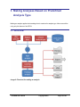
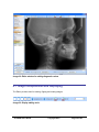
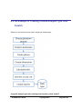
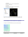
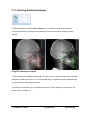
1
AX.CEPH CEPHALOMETRY SOFTWARE DOCUMENTATION Ax.CEPH Users Guide Audax d.o.o. Tehnološki park 18 Ljubljana, SI -1000 Telephone 00 386 1.200.40.50 • Fax 00 386 1.423.47.00 www.axceph.com Ax.CEPH Users Guide Copyright 2010 Page 2 of 98 Table of Contents 1 2 3 4 5 6 ABOUT THIS GUIDE ......................................................................................................................5 1.1 W HO SHOULD USE IT .................................................................................................................6 1.2 TYPOGRAPHICAL CONVENTIONS .................................................................................................6 INTRODUCTION.............................................................................................................................7 2.1 PURPOSE ..................................................................................................................................7 2.2 GLOSSARY ................................................................................................................................8 2.3 PROGRAM W INDOW LAYOUT ......................................................................................................9 MAKING ANALYSES BASED ON PREDEFINED ANALYSIS TYPE ...........................................10 3.1 W ORKFLOW .............................................................................................................................10 3.2 PREPARING DATA FOR THE ANALYSIS .......................................................................................11 3.3 PRINTING AND SAVING .............................................................................................................28 DIGITAL FILTERS IN IMAGE PROCESSING ..............................................................................29 4.1 IMAGE MANIPULATIONS AND DISPLAYING....................................................................................30 4.2 FILTERS ..................................................................................................................................33 4.3 SHOW .....................................................................................................................................38 4.4 ANNOTATIONS, SYMBOLS..........................................................................................................39 4.5 INTERACTIONS .........................................................................................................................42 4.6 HISTORY .................................................................................................................................43 4.7 CHANGING BACKGROUND COLORS ...........................................................................................44 4.8 STORING DERIVED IMAGE.........................................................................................................44 VIEWING ANALYSES PERFORMED ..........................................................................................45 5.1 SOFT COPY..............................................................................................................................45 5.2 HARD COPY .............................................................................................................................45 CREATING A CUSTOM ANALYSIS TYPE ..................................................................................47 6.1 HOW TO START ........................................................................................................................48 6.2 GEOMETRIC FEATURES ............................................................................................................49 6.3 MEASUREMENTS ......................................................................................................................54 6.4 AN EXAMPLE OF CREATING CUSTOM ANALYSIS TYPE FROM SCRATCH .......................................58 6.5 AN EXAMPLE OF HOW TO MEASURE WITS APPRAISAL ................................................................62 6.6 COLORS ..................................................................................................................................65 Ax.CEPH AxCEPH.docx Copyright 2010 Page 3 of 98 6.7 EDITING STANDARD VALUES AND STANDARD DEVIATIONS............................................................66 6.8 LINKING STANDARD VALUES AND STANDARD DEVIATIONS WITH ANGLES AND MEASUREMENTS ....67 6.9 LAYERS ...................................................................................................................................68 6.10 PRINTOUT CUSTOMIZATION .......................................................................................................70 6.11 EXPORT TO MS EXCEL.............................................................................................................73 6.12 CREATE AN EXCEL TEMPLATE ..................................................................................................74 6.13 SAVING ANALYSIS TYPES ..........................................................................................................79 7 CREATING ANALYSIS TYPE FROM PREVIOUSLY STORED TYPE ........................................80 8 CREATING ANALYSIS TYPE USING PREDEFINED ELEMENTS .............................................81 9 SUPERIMPOSITION.....................................................................................................................84 9.1 SUPERIMPOSING ANALYSIS OVER ANALYSIS ..............................................................................85 9.2 SUPERIMPOSING PHOTO IMAGE OVER ANALYSIS .......................................................................89 9.3 USING DISPLAY TOOLS ............................................................................................................90 9.4 TOOLS FOR SETTING POINTS MANUALLY ...................................................................................90 9.5 EXPORT PICTURE ....................................................................................................................92 9.6 ANALYSIS AND SUPERIMPOSITION RELATION .............................................................................92 10 ABOUT PANEL .........................................................................................................................93 10.1 LANGUAGE ..............................................................................................................................93 10.2 DISPLAYING APPLICATION DATA ...............................................................................................93 10.3 ENTERING A PRODUCT KEY ......................................................................................................93 11 AX.CEPH SETUP ......................................................................................................................94 11.1 APPLICATION SETUP ................................................................................................................94 11.2 UNLOCKING APPLICATION FEATURES ........................................................................................96 Ax.CEPH Users Guide Copyright 2010 Page 4 of 98 1 About this guide This document is divided into the following chapters: Chapter 1, “About this guide”. Chapter 2, “Introduction”, introduces our Ax.CEPH software Chapter 3, “Making analyses based on predefined analysis types”, explains how to get started. Chapter 4, “Digital filters in image processing”, describes filters and methods for digitaly enhancing x-ray images. Chapter 5, “Viewing analyses performed”. Chapter 6, “Creating a custom analysis type”, introduces tools to make any analysis type. Chapter 7, “Creating analysis type from previously stored type”, explains how to shorten a new analysis type development by using existing type and changing it. Chapter 8, “Creating analysis type from previously stored type”, explains how to shorten a new analysis type development by using predefined measurements from the database. Chapter 9, “Superimosition”, explains how to place analysis over analysis or photography over analysis. Chapter 10, “About panel”, explains additional features for software setup Chapter 11, “Ax.CEPH setup”, explains how to install the Ax.CEPH software and enter the key to unlock additional functionalities. Ax.CEPH AxCEPH.docx Copyright 2010 Page 5 of 98 1.1 Who Should Use It This guide is intended for users of different degrees of knowledge and experience with the Ax.CEPH software: Users: The users who will use Ax.CEPH as a routine tool Advanced users: The users who will develop their own analysis types Researches: The developers who will use Ax.CEPH as a research tool This guide assumes that you have some knowledge of the Windows operating. 1.2 Typographical Conventions This document uses the following typographical conventions: Command and option names appear in bold type in definitions and examples. The names of directories, files, machines, partitions, and volumes also appear in bold. Variable information appears in italic type. This includes user-supplied information on command lines. In addition, the following symbols appear in command syntax definitions. Square brackets [ ] surround optional items. Angle brackets < > surround keyboard user-supplied values. Pipe symbol | separates mutually exclusive values for an argument. Ax.CEPH Users Guide Copyright 2010 Page 6 of 98 2 Introduction 2.1 Purpose Analyzing a cephalometric x-ray image is a part of diagnostic procedures in jaw and dental orthopedics. In addition dentists can use it to determine a toothless patient's occlusal plane. It is based on a transilluminated radiograph of the head onto which landmark points and lines/planes are placed. Based on the measurement between landmark points in hard and soft tissue, are prepared tables and diagrams, containing deviations from values that are normal for teeth in a given age or race. There are several analyses and analysis interpretations available by authors like Ricketts, Downs, Steiner, Segner and others. Besides standard analyses dentists, orthodontists or surgeons can make additional ones. This makes it easier for them to formalize irregularities, define virtual planes or set a course of treatment. Considering the diversity of cases and the time used, computer software can greatly aid specialists in making routine, but critical calculations in analyses. Ax.CEPH is a program that enables you to integrate your specialist knowledge into the computer and reuse it in cephalometric X-ray image analysis. The program allows users to make their own analysis types or make additional measurements in a given analysis. This User Manual is structured in a way that those completely new to the program can become productive as soon as possible. Advanced users should see follow-up for detailed treatment of designing their own analysis types. Ax.CEPH AxCEPH.docx Copyright 2010 Page 7 of 98 2.2 Glossary This User Manual uses some terms that are specific for the program. This glossary explains those terms. Plane Radiographic cephalometry often refers to straight lines from the two-dimensional world of x-ray images as planes. Planes are represented as lines, because they are perpendicular to the radiograph and viewing them from the side makes one of their dimensions invisible. Both terms plane and line, will be used in this Manual. Point Setting cephalometric points/landmarks is the basic task of an analysis. Measurement A measurement is any determined property, be it a distance, angle or calculated value. Layer Layers are used to group elements as required, for example by properties. When printing, only elements included on the print layer are printed. Analysis An analysis is the concrete processing of a patient's radiograph. Results of analyses are measurements of correlations between hard and soft tissue and their comparison with standard values. Results can be displayed on-screen, printed out or exported to an Excel spreadsheet. Analysis type An analysis type is the computerized correlations between cephalometric points and planes, cephalometric measurements in comparison with standard values, and a specific method of displaying results. Examples are Downs Analysis, Ricketts Analysis, Steiner Analysis, etc. Ax.CEPH Users Guide Copyright 2010 Page 8 of 98 2.3 Program Window Layout The program screen is divided into a number of areas. Image 1: Ax.CEPH program window layout The Command Ribbon changes according to the type of task: making analyses, designing analysis types, superposing images. View Icons allow hiding or revealing single types of primitives in the image. The Model Tree provides easy browsing of the primitives in the analysis. The Splitter allows resizing the canvas at the expense of the tree, and vice versa. The Canvas contains the image and the analysis' primitives. The Dashboard contains information about and settings of the currently selected element. Ax.CEPH AxCEPH.docx Copyright 2010 Page 9 of 98 3 Making Analyses Based on Predefined Analysis Type Making an analysis applies the knowledge that is contained in analysis type. Most users will be using only this feature of Ax.CEPH. 3.1 Workflow Image 2: Flowchart for making an analysis Ax.CEPH Users Guide Copyright 2010 Page 10 of 98 A given analysis type includes data about: 1. geometry (landmarks and planes) and measurements, 2. measurements and their correlations to standard values, 3. printout, and 4. template for exporting to Excel. When making an analysis, these are applied to concrete radiographs. Making an analysis based on a predefined analysis type is simple and involves the following steps: 1. Preparing Data for the Analysis: a) selecting x-ray image, b) entering data about the patient, his or her status, analysis and x-ray procedures, c) selecting analysis type. 2. Identifying landmark points and outlines: a) correctly placing offered landmark points onto the radiograph, b) calibrating the image, c) creating or editing outlines (teeth, hard and soft tissue). 3. Printing and saving: a) printing out, b) exporting to Excel, c) sending by e-mail, d) saving. 3.2 Preparing Data for the Analysis 3.2.1 Selecting an X-ray Image Start a new analysis by clicking the New analysis button. A dialog box opens where you locate and select the desired image. Most standard image file types are supported (BMP, JPG, TIF, GIF) as well as single-image DICOM files. In the case of DICOM files, the dialog offers you the option for extracting metadata (the name of the patient, when the x-ray was taken), so you don't need to enter it manually. Ax.CEPH AxCEPH.docx Copyright 2010 Page 11 of 98 Image 3: Opening an x-ray image for the analysis 3.2.2 Entering Data about the Patient, His or Her Status, Analysis and X-ray Procedures Data about the patient and the analysis are entered into the Dashboard in the bottom section of the program window. The Dashboard changes according to the currently selected element in the tree or on the canvas. Select the Data element for entering patient data. Image 4: Dashboard of the Data element Ax.CEPH Users Guide Copyright 2010 Page 12 of 98 Image 5: Data about the patient and the analysis Data can be entered and changed anytime during the analysis. Ax.CEPH AxCEPH.docx Copyright 2010 Page 13 of 98 3.2.3 Selecting an Analysis Type Select a predefined analysis type by clicking the Add type button in the Dashboard. Image 6: Dashboard section where the analysis type is set, and the analysis type selection dialog box In the analysis type selection dialog, check the analysis type based on which you wish to make the analysis. Click the OK button. Unplaced geometric elements that are used in the analysis appear on the image. This state is called raw analysis. 3.2.4 Correctly Placing Offered Landmark Points onto the Radiograph Ax.CEPH Users Guide Copyright 2010 Page 14 of 98 After identifying reference points and defining outlines, the analysis is ready to be printed, exported, saved or sent by e-mail. 3.2.5 Selecting Elements Elements can be in one of three states. a) Set – a set element is placed onto the canvas and designates a point, plane, etc. b) Highlighted – an element is highlighted when the mouse pointer (green crosshairs) is placed on it; the element turns light blue. An element can be highlighted by moving the mouse pointer near it or its label. c) Selected – an element is selected after left-clicking on a highlighted element. The element turns red. Elements can also be selected in the tree. This comes in particularly handy for elements that are hidden. Image 7: The selected element is highlighted in the tree and colored red on the canvas. If an element depends on other elements (parent – child relationship) and is selected, all parents of that elements turn purple (see Image 10: Moving a point on a line to a new position). 3.2.6 Element Icons in the Tree Ax.CEPH AxCEPH.docx Copyright 2010 Page 15 of 98 The icons of elements in the tree come in different shapes and sizes, each with its own meaning. Colors: A red element is included in the structure and is completely undefined. A yellow element is included in the structure, it identifies a feature, but it is in the initial position. A green element is defined and moved to the designated position. Icons: point measurement – length line measurement – angle outline measurement – calculation A grey icon background (e.g. ) means that the element is currently hidden. 3.2.7 Moving a Point Moving a point behaves differently according to the relation of a point to other geometric elements. 3.2.7.1 Single point Image 8: Selecting a point A single point is one that is not bound to any other geometric element (like a line). It can be moved freely in any direction. First select the point (place the mouse pointer on it to highlight it, then left click), then drag it to the desired position. Ax.CEPH Users Guide Copyright 2010 Page 16 of 98 Image 9: Moving a point to a new position Select a point by clicking it directly (see Error! Reference source not found.or, alternatively nd often more practical, click the point's label (see Image 9b) then drag it to the desired position. 3.2.7.2 Point on a Line Image 10: Moving a point on a line to a new position A point that is on a line is distinguished by its color. It is good practice to give elements of the same type but with different characteristics different colors. By default, a point on a line is creamcolored; its label and outline are olive green. Existence of such point depends on the existence of the line it is on. If the line, which is in that case a parent, is deleted, the point is also deleted, because it is the line's child. If the line is moved, the point on it is moved also. 3.2.7.3 Point at the Intersection of Lines Image 11: A point at the intersection of two lines A point that is on a line is distinguished by its color. By default, a point at the intersection of lines is cream-colored; its label and outline are dark grey. Existence of such a point depends on the existence of two intersecting lines. If the intersecting lines, which are in that case parents, are Ax.CEPH AxCEPH.docx Copyright 2010 Page 17 of 98 deleted, the point is also deleted, because it is the lines' child. Moving any of the lines moves the point to the new intersection. Note: Lines are infinite in length in both directions. But they are displayed as line segments with small extensions at both endpoints. The intersection of two lines can therefore be outside the displayed line segments. Image 12: A point at the implied intersection of two lines (Plane 1 and Plane 2) 3.2.8 Moving a Line/Plane Moving a line behaves differently according to the relation of a point to other geometric elements. 3.2.8.1 Single Line Image 13: Moving a single line A single line can be moved in two ways. Ax.CEPH Users Guide Copyright 2010 Page 18 of 98 a) By moving one of the two green endpoints. The other endpoint remains in place, the line is resized and rotated to follow the moving endpoint. b) Selecting a line anywhere in between the endpoints moves the whole line without resizing it. 3.2.8.2 Line Through One Point Image 14: Moving a line that runs through one point If a line is the child of a point, it can be moved in two ways. a) By moving the green endpoint. The point remains in place; the line is resized and rotated to follow the moving endpoint. b) By moving the line's parent point. Select and move the point as described above. The green endpoint remains in place; the line is resized and rotated to follow the moving point. Such lines cannot be selected as a whole and moved around. 3.2.8.3 Line through two points Image 15: A line that runs through two points A line that is the child of two points can only be moved by moving one of the two points. Such lines are colored blue. Ax.CEPH AxCEPH.docx Copyright 2010 Page 19 of 98 Image 16: Moving a line's endpoint causes the line's child elements to move accordingly It may happen that a point is moved indirectly because its parents are moved. With proper positioning, you can construct a complex "mechanism" (analysis type). 3.2.8.4 Perpendicular Lines Image 17: Moving a perpendicular line A perpendicular line is colored brown. The perpendicular of a selected line turns purple. Move it by clicking anywhere between the endpoints and drag it around. In the special case when the position of a perpendicular is limited with a point, you can move the perpendicular by moving the point. Ax.CEPH Users Guide Copyright 2010 Page 20 of 98 3.2.8.5 Parallel lines Image 18: Moving a parallel line A parallel line is colored brown. The parallel of a selected line turns purple. Move it by clicking anywhere between the endpoints and drag it around. In the special case when the position of a parallel line is defined with a point, you can move the parallel by moving the point. 3.2.8.6 Verticals and horizontals Verticals and horizontals are special lines that are always vertical or horizontal, respectively, no matter how the image is rotated. Move such lines by clicking anywhere between their endpoints and drag them to the desired position. 3.2.9 Image Calibration Image calibration is a procedure whereby the length of and distance between objects is determined based on the known length of any element. An x-ray image usually contains a ruler next to the forehead; the Calibration element has a circle icon in the tree. Image 19: The Calibration element and the ruler Ax.CEPH AxCEPH.docx Copyright 2010 Page 21 of 98 Image calibration starts by selecting the Calibration element in the tree. The Dashboard changes. Image 20: The Dashboard for image calibration Click two points on the radiograph ruler and enter their distance in millimeters. If you want to change the points press <Delete> or the Calibrate again button and repeat the procedure. 3.2.10 Creating and Editing Outlines (hard and soft tissue) Outlines can be predefined (teeth) or created manually by placing points around an area. 3.2.10.1 Teeth Image 21: The Teeth menu Selecting a predefined tooth adds three interdependent elements to the canvas and the tree: two points and the outline of a tooth. The points are the outline's parents; if either point is deleted, so is the whole outline. Delete an element by selecting it and pressing the <Delete> key. Image 22: A tooth in the tree and on the canvas The newly added tooth has a blue dashed bounding box around it. Ax.CEPH Users Guide Copyright 2010 Page 22 of 98 Image 23: Resizing and moving a tooth Width: It can be changed by clicking a tooth’s outline (it turns red from pink and the bounding box appears) and dragging the resize handle on the bounding box to the desired position. Position: a tooth can be moved around by dragging its two points to the desired position. Read more about tooth positioning in the follow-up in chapters about creating analysis types. 3.2.10.2 Hard and soft tissue Other structures can be marked by manually creating outlines with the Outline tool. Image 24: Click to place the outline's nodes Ax.CEPH AxCEPH.docx Copyright 2010 Page 23 of 98 Right click where you want to start the outline then click around the structure you wish to outline. Double-click to finish the outline. Image 25: Selected and deselected outline An outline can be edited: 1.) by clicking and dragging nodes, or 2.) by deleting nodes (hold the <Ctrl> key and click a node). Deleting any of the two end nodes will delete the whole outline. All outlines are by default on the print layer and therefore appear on the printout. Remove them by using the editing tools. 3.2.11 Zoom WIndow The Zoom window can be opened or closed (if it is open) by pressing the <F2> key. It can be resized and moved around. The program remembers the last used size and position of the Zoom window. The Zoom window displays a magnified view around the mouse pointer. No elements are displayed in the zoom view. Ax.CEPH Users Guide Copyright 2010 Page 24 of 98 Image 26: The Zoom window when moving a point When moving a point, the Zoom window displays a crosshairs marking the center of a point, even if the label was selected. Click the Negative button to display the vicinity of the crosshairs in negative, or the Contrast button to improve the contrast. 3.2.12 Info Window The Info window can be opened or closed (if it is open) by pressing the <F3> key. It can be moved around and the program remembers the last used position. The Info window displays information about the currently selected element: name, image and note. Ax.CEPH AxCEPH.docx Copyright 2010 Page 25 of 98 Image 27: The Info window 3.2.13 Element Commands Elements offer a number of advanced options. Select an element in the tree or on the canvas. Right-click to open the context menu with a number of options. Image 28: An element's context menu Ax.CEPH Users Guide Copyright 2010 Page 26 of 98 3.2.13.1 Hide/Show Elements can be hidden and revealed as necessary. The element's icon in the tree changes accordingly. 3.2.13.2 Show text All elements have labels that can be visible or hidden on the canvas. Use this command to toggle a label's visibility. 3.2.13.3 Rotate to Horizontal The image can be arbitrarily rotated. Select a line and right click. Select Rotate to Horizontal from the context menu. This makes the selected line horizontal and the whole image is rotated to match. Image 29: Image rotation Ax.CEPH AxCEPH.docx Copyright 2010 Page 27 of 98 3.3 Printing and Saving 3.3.1 Printing Start printing by clicking the Print button. Printed are: analysis information, x-ray image, analysis elements on the print layer, and the measurements table. The analysis is saved automatically before printing. 3.3.2 Export to Excel Export the analysis to Excel by clicking the Excel button. Excel uses the template that comes with an analysis type. The analysis is saved automatically before printing. 3.3.3 Send by E-Mail Send an analysis by e-mail by clicking the e-mail button. The analysis is sent as a single file containing all information for the recipient to view and edit it. 3.3.4 Saving Save an analysis by clicking the Save Analysis button. The created file's name contains key information, for example the file Jane_Doe_2_4_2008_1.acx tells us: Jane_Doe_: the patient's name is Jane Doe; 2_4_2008_: the analysis was done on April 2, 2008; 1: this is the patient's first analysis on that day. Ax.CEPH Users Guide Copyright 2010 Page 28 of 98 4 Digital Filters in Image Processing At any time during the analysis you can use digital filters to process the image and improve its diagnostic value. That is, make it darker, lighter, use specially designed filters for highlighting soft tissue, etc. Use Ax.CEPH to store images as derived images. Click the Edit button in the Image group of the command ribbon to run the editor. Image 30: Edit button Switch between displaying derived and original images at will. To do so, select them in the tree. The Active image element shows the currently displayed image. Image 31: Active image in the tree Ax.CEPH AxCEPH.docx Copyright 2010 Page 29 of 98 Image 32: Editor window for editing diagnostic values 4.1 Image manipulations and displaying The Editor provides tools for resizing, flipping and rotating images. Image 33: Display editing tools Ax.CEPH Users Guide Copyright 2010 Page 30 of 98 Layout of the derived image. Two-image layout. The original image is displayed on top, the derived image at the bottom. This option is especially useful for digital panoramic dental x-rays – that is, comparing the derived image with the original. Two-image layout. The original image on the left, the derived image on the right. This option is useful for intra-oral x-ray images – comparing the same area in the derived image and the original. Resize image to fit window. Show full-sized image. Flip image horizontally. Flip image vertically. Rotate image 90 degrees counterclockwise. Rotate image 90 degrees clockwise. Set custom zoom. Preset values available are: 50%, 70%, 100%, 200%, and 500%. You can type in any value. Image 34: Description of image manipulation and displaying Use the editor to view and edit derived and original images. The name of the currently open image is displayed in the titlebar. Ax.CEPH AxCEPH.docx Copyright 2010 Page 31 of 98 Image 35: Various layout options Use the mouse wheel to zoom the image in or out. Turn the mouse wheel towards you to zoom out, or away from you to zoom in. If the image is zoomed in to a level where it no longer fits the screen, the Navigator window appears for easier orientation around the image. Image 36: Navigator A dashed bounding box borders appear in the Navigator window, marking which area of the image is displayed. Place the mouse pointer over the box (the pointer changes to a crosshairs), left-click and drag the box to quickly navigate the image. Close the Navigator by clicking the cross (x) icon. It is closed automatically when displaying the whole image. You can also use the sliders on the right and at the bottom to move around the image. Or, simply click in the image, hold and move in the desired direction. In the bottom section you can find a toolbar. Use it to modify brightness and contrast levels. Initially the values are by default set to 0 (zero). That is, contrast and brightness are set at neutral levels. Ax.CEPH Users Guide Copyright 2010 Page 32 of 98 Note: CONTRAST AND BRIGHTNESS LEVELS ARE GENERALLY BEST LEFT AT THEIR DEFAULT VALUES. OTHERWISE SOME INFORMATION IN THE IMAGE MIGHT BE LOST. 4.2 Filters The Filters section contains a selection of digital image processing tools. Apply them to the whole image or just to a selected area. To only change a selected area, click ROI (region of interest) in the Show menu (that is, place the pointer in the top left corner of the selected area and drag it to the bottom right corner and release the button). You can resize and move the selected area after applying specific filters. The filters and area get recorded in the History table in consecutive order. Image 37: Filters The data contained in the History table is important since filters are applied consecutively. The filter commands are assigned the following function keys (except for the Negative option) from <F2> to <F7>. 4.2.1 Median Deletes irregular points which deviate from the image. If a bright dot appears inside a dark field, an error during image capture must have occurred. Using the filter removes such errors. 4.2.2 Softening Use Softening to remove blurred edges between objects in the image. 4.2.3 Sharpening Use Sharpening to emphasize borders between bright and dark areas in the image. For example, sharpen the image in order to highlight the bone structure. Ax.CEPH AxCEPH.docx Copyright 2010 Page 33 of 98 Image 38: Window for setting parameters for sharpening Selecting this filter opens a new window. According to how you set display options, you can simultaneously view the original image (marked with Before) and the resulting image (marked with After). Of course, you can display only the image which is the result of sharpening. The same imaging functions are available as in the editor (zoom, move, and navigator). Use sliders to set the factor and radius and focus the image as best as possible. It is recommended that you take care in setting these two parameters. Warning! Do not change the parameter Stand. Dev. By default it is set to values between 0.1 and 0.8. The radius is used to determine the size of the area for sharpening (the greater the radius the greater the area calculated for sharpening). Proceed by setting the factor to determine the sharpening magnitude. To reset default values, that is, radius=3 and factor=300, click Reset. After setting the values, click Ok. They are saved as default and will be applied when running Sharpening again. Ax.CEPH Users Guide Copyright 2010 Page 34 of 98 4.2.4 Emboss A relief can be generated based on the color information in the image. Increasing the radius raises the embossing height. 4.2.5 Gray Level Correction Use gray level correction to set brightness and contrast of images without diminishing the quality of the original image. The human eye can perceive around 40 different shades of gray. On the other hand, the computer can display 256 shades of gray (8 bits; 28=256). In addition you can print them onto transparencies. The medical image is comprised of 12-bit pieces of information. Hence the image contains 4096 shades of grey (212=4096). The computer displays batches of 16-bit grayscale data as one. Internally, the image is still 12-bit. That is why you can retrieve the quality of the original image by additional transformation of the derived image. Image 39: Preview window for gray level correction Ax.CEPH AxCEPH.docx Copyright 2010 Page 35 of 98 Clicking Gray level or pressing <F6> displays a window, where you can change parameters accordingly. The bottom section displays two charts. The left-hand side chart represents the gray level of the input image. The right-hand one represents the output image. Move the slider under the input image chart to set the desired gray level. Image 40: Parameters for correcting gray levels Move the red handle to the left to make the image brighter, and move it to the right to make it darker. Move the green handle to expand or shrink the range. Only the range between the green and blue handle will be used. Note: Moving these handles to the middle range results in the loss of information however it will result in changing contrast and brightness of an image. Image 41: Example of setting contrast Note: Gray level correction is one of the most important operations. Ax.CEPH Users Guide Copyright 2010 Page 36 of 98 4.2.6 Soft Tissue Cephalometric images are usually quite bright due to transillumination of the head. Use the Gray level filter to make them darker. This way you lose the information on soft tissues which may be crucial in diagnostics, planning, etc. Hence determine the area in the nose (let us say it covers a fifth of the image on the right-hand side) where the soft tissue filter will be applied. Then select Soft tissue to apply it in the selected area. You can repeat the procedure until you get the right results (normally, repeating it twice should do it). Step-by-step preparation of cephalometric image 1. Use Gray level (for darker sections of the image) to display hard tissue properly. 2. Then mark the area (see the next section) to apply the filter. 3. Select the Soft tissue filter or press <F7>. Repeat the procedure until you get a suitable result. Image 42: Using soft tissue filter in grayscale from black to white Set the ROI area to apply Soft tissue operation between the two lines (see above). Ax.CEPH AxCEPH.docx Copyright 2010 Page 37 of 98 4.3 Show The Show menu offers two functions. Use them to specify the area where an operation will be used or for highlighting grays with a different color. Image 43: Show menu 4.3.1 ROI (region of interest) Set an area by clicking the top left corner of the area and drag the pointer to the bottom right corner. Then release the button. Image 44: Area ROI (Region Of Interest) You can modify the area when black squares are displayed in corners and in the middle. Drag and drop the squares to resize it at will. 4.3.2 Pseudo color Use this function to display any grayscale image using red, green and blue. Ax.CEPH Users Guide Copyright 2010 Page 38 of 98 Image 45: Window for setting pseudo colors Changing the amount of red, green and blue in turn changes the color scheme of the derived image on screen. After finishing and closing the window, the image is changed back to grayscale (that is, it is returned to the original version before having used Pseudo-color function). Images where pseudo colors have been applied cannot be stored as derived images. 4.4 Annotations, symbols You can insert annotations to the image. That is, graphical symbols, text or their combination. Image 46: Annotations and symbols 4.4.1 Annotation Ax.CEPH AxCEPH.docx Copyright 2010 Page 39 of 98 Select Annotation from the Annot., symbols menu. Hover over the image and left click thus selecting the area where you can enter text. You can change the annotation at any time (that is, change the content, font, color, positioning). Having entered the text, press <Enter>. Image 47: Inserting annotation To change the size, color or font of the text, you first have to select it (if the field is not selected, use the command Choose object in the Interactions menu). Then right click the text box, to open the menu where you can select Settings. Image 48: Window for editing annotation A new window opens where you can set the style (font, color, size, etc.). The line width is the width of the frame. Here you can also change the text at will. Image 49: Content does not fit frame When the text does not fit the frame or the frame is too big, resize the frame accordingly. That is, select it (left-click the annotation having first selected Choose object in the Interactions menu) and move the black squares to fit accordingly. You can also move the selected text. Ax.CEPH Users Guide Copyright 2010 Page 40 of 98 Image 50: Expanded frame To remove annotation you have to select it first. Then right click it and select the Delete option. You can also delete it by pressing <Delete>. 4.4.2 Line with annotation To insert a line with annotation in the derived image, select Line with annotation from the menu. Left click the image and hold down (see item 1 in the image) and then drag the line to the designated position (see item 2). On releasing the mouse button a new window is opened. Here you can edit annotation (the same options are available as when editing text). Add any text to the field and click OK. Image 51: Line with annotation Whenever you want to make changes to annotation or symbols, you have to select it first. Hover with the pointer over the item 2 and right-click it. Then select Settings. A window for modifying settings is opened. Set the parameters accordingly and click OK. To move the line, you first have to select it. Place the pointer on item 1 and left click it and hold down. Drag it to the desired position. Do the same with item 2. To move the entire object, place the pointer on one of the items so that the pointer changes to a crosshairs. Then left click, hold down and move it to the desired location. Delete the line the same way as the text. Ax.CEPH AxCEPH.docx Copyright 2010 Page 41 of 98 4.4.3 Memo This option is different from the Annotation option because it lets you enter multiple lines to the note. Plus, by default the color of the frame is different than the color of the text. Otherwise all the operations are like the ones mentioned above (see Annotation). The only difference is in how you insert or change text. 4.4.4 Line and Square To mark the area more easily, use lines and rectangles. They can be used like all other objects. Plus, you can change color and line width. 4.5 Interactions We have already dealt with some of the options offered in the Interactions menu. Image 52: Line with annotation 4.5.1 Move Having resized the image so that it does not fit the window (in such a case the Navigator is displayed), you can move in it by left-clicking the image, holding down the button and moving to the desired position. 4.5.2 Zoom to selection Selecting Zoom to selection maximizes the selected section of the image to screen size. Mark the section you want to view with a dotted rectangle and the rest is done automatically. Ax.CEPH Users Guide Copyright 2010 Page 42 of 98 4.5.3 Choose object We have already dealt with the Choose object option but we have always selected only one object. Sometimes you want to select multiple objects (for example to delete them). Place the pointer on the edge of the last object and left click it, hold down the button and select all the other objects. The selection is confirmed with black squares displayed on the edges. 4.6 History 4.6.1 The history table The History table records all the filters that have been applied. The Region column displays whether the operation was performed on the entire image or only on a particular area. If the operation is checked, this means it was performed. You can check the boxes or leave them unchecked. The derived image is changed accordingly. In order not to perform a certain operation, uncheck it so that it will not be applied. To completely remove a specific operation, mark it so that it is selected (blue) and click Delete filter or press <Delete>. Image 53: Operations history list 4.6.2 Storing History – PRESCRIPTION CTRL+R After having entered all modifications and you would like to store operations history, you can store it as a prescription. Press the key combination <CTRL> <R>. A new window is opened where you click Save history as prescription. Then enter the name of the prescription and confirm it. In the next step, assign any of the function keys <F9> to <F12> to the prescription. To assign a function key, drag-and-drop the prescription on it. Ax.CEPH AxCEPH.docx Copyright 2010 Page 43 of 98 Image 54: Assigning key to prescription The operations are displayed together with the parameters in the right-hand side window. You can delete it by marking it and selecting Delete prescription. Selecting the assigned prescription key deletes only this. But having selected prescription, then both the assigned key and the prescription are deleted. 4.7 Changing Background Colors Change background color in the editor by pressing <CTRL><B>. A color scheme is displayed where you can make appropriate changes. Confirm it by clicking Ok. 4.8 Storing Derived Image Having finished operations and you are satisfied with the way the derived image turned out, you can store it. The following options are available: 1. Click Save 90% quality which is suitable for sending by e-mail due to its small size. 2. Or, click Save 100%; which is suitable for later printing. Regardless of the option you use, the image quality is sufficient for performing analyses. Ax.CEPH Users Guide Copyright 2010 Page 44 of 98 5 Viewing Analyses Performed 5.1 Soft copy 5.1.1 Opening an Analysis To open an existing analysis, click the Open analysis button and select the analysis. 5.1.2 Changing an Analysis In an open analysis, the positioning of points and planes can be changed, elements and measurements added and removed. To save the analysis under the old (the existing) name, click Save analysis. But should you want to save the modified analysis under a new name or to keep it before applying changes, click Save as and save the analysis under a different name. The patient’s name is offered by default. 5.1.3 Send Analysis by E-Mail Click to send the analysis by e-mail. An e-mail message is opened. Here you have to enter a recipient, the subject and body of the message. A file containing the analysis with all the required data is attached to the message. 5.2 Hard copy Ax.CEPH AxCEPH.docx Copyright 2010 Page 45 of 98 5.2.1 Print Click the Print button to print an analysis. A preview window is opened where you click in the top left corner to print the analysis. The patient’s radiograph can be found on the left-hand side of the printout. Any additional graphical elements of the analysis can, on the other hand, be found top right. The bottom section displays analysis results organized in columns. Click Prepare report to edit displayed results and order them into lists. For more information on editing printouts see follow-up (topic on how to create analysis type). Image 55 Analysis printout Ax.CEPH Users Guide Copyright 2010 Page 46 of 98 6 Creating a Custom Analysis Type Create an analysis type in one of the following three ways: 1. by modifying an existing type, 2. using predefined elements, 3. from scratch. Image 56: Ways of creating a new analysis type Ax.CEPH AxCEPH.docx Copyright 2010 Page 47 of 98 6.1 How to start To create a new analysis type, first select the Analysis type tab above the tools banner and click New type. A new window is opened where you can enter the name of the new analysis type. Image 57: Entering name of new analysis type Enter the name of the new analysis and confirm it by clicking Ok. A generic window for creating new and phantom analysis is opened. Switch views by clicking Choose phantom picture. Ax.CEPH Users Guide Copyright 2010 Page 48 of 98 Image 58: Basic analysis type window Clicking the first item in tree (item 1 in the image above), opens the Dashboard where you can change the name of the analysis type (2) and add the existing type to a new analysis type (3). The date can also be inserted. 6.2 Geometric Features Geometric features consist of primitives (such as points, planes and outlines). They appear as independent elements or are related to other geometric features (e.g. a point lies on the line). Add these features to the analysis type using the following commands that can be found in the Tools group in the command ribbon: Ax.CEPH AxCEPH.docx Copyright 2010 Page 49 of 98 Image 59: Inserting geometric features Some buttons consist of two parts. Click the upper part to add individual features. On the other hand, clicking the bottom part opens a dropdown menu from which you can select the method for connecting a feature to other elements in the analysis type. The features in the analysis type can have two statuses (colored differently in the tree). The newly-inserted component is always undefined. In contrast to the analysis, the features cannot be colored green when creating analysis type because you cannot determine their precise position. You can only set their initial position. A red element is included in the structure and is completely undefined. The feature is inserted in the image, status identified and it is in initial position. To define the status and determine the initial element position, select it in the tree and place it in the image. Change the name and label of the element (make the label visible or hide it by checking or unchecking Show) in the Dashboard. In addition, you can enter a text description (Desc.) of the element, change its color and filling color, and set layers. You can also add a drawing of its position in the image. All settings can be viewed in the editor which can be opened pressing <F3>. Image 60: Geometric features’ Dashboard where you change various properties Ax.CEPH Users Guide Copyright 2010 Page 50 of 98 6.2.1 Point Click Point on the ribbon to add a point in the analysis type which you can then define as needed. 1. To add a point, click Point and set it anywhere you want in the image. Later you can move it around at will. 2. Click Point, select Point on plane and place the point on the desired line. Move the point along the line. 3. Click the Point icon and select Point on cross section. Place the point on the cross section of two lines. Change the color of a point (border of the point and label) and fill color (point surface) at will. The default color changes according to the type of point, that is, whether it is a point on plane or a point on cross section. Note: Ax.CEPH stores the last element that was inserted in the analysis type. Pressing <F4> creates a new element of the same type. Hence you can use this shortcut instead of continuously clicking the same button in the command ribbon. 6.2.2 Plane Use one of the following types of planes: 1. independent (simply click any two points on the canvas), 2. child of a point: click an existing point and then anywhere on the canvas, 3. child of two points: click two existing points on the canvas. Ax.CEPH AxCEPH.docx Copyright 2010 Page 51 of 98 Create a parallel line in one of the following two ways: 1. Parallel plane through a point: First select a plane parallel to the existing plane and then just select a point through which the parallel plane should go. 2. Parallel plane: First select a plane parallel to the existing plane and click anywhere on the canvas. Create a perpendicular plane in one of the following two ways: 1. Perpendicular plane through a given point: First select a plane perpendicular to the existing plane and then just select a point through which the perpendicular plane should go. 2. Custom perpendicular: First select an existing plane, and then click anywhere on the canvas to add the perpendicular. In addition there are two special planes, that is, the horizontal and vertical plane. You can move these two planes only translationally and their direction remains fixed. That is, regardless of the image rotation used. You can use them in measurement and calculations like all other types of planes. 6.2.3 Outline/Silhouette Insert outlines to analysis types like any other feature. Define outlines by selecting it in the tree, clicking in the canvas and start creating the outline. Additional clicks create new nodes of the outline. Finish by double-clicking. You cannot connect outlines to other elements. Change the shape of the created outline by dragging and dropping individual points, or by deleting them (delete any point by pressing <CTRL> + click outline, deleting an endpoint deletes the outline). To move the outline translationally, click anywhere between the endpoints and move it. Change the label, name, description, color or layer the same way as with other elements. An existing point cannot be an outline's node. Ax.CEPH Users Guide Copyright 2010 Page 52 of 98 6.2.4 Teeth Outline To add a tooth outline into an analysis type, select it from the Teeth dropdown. There are four predefined teeth outlines available, that is, upper and lower incisor; and upper first and lower first molar. In contrast to other features, these outlines are predefined and are set in the default position. Plus, a tooth outline consists of three components, that is, two points and outline. The outline is in child relation to the two points (thus deleting a point deletes the outline as well). Image 61: of tooth outline, tooth in default position in analysis, interactive points of tooth outline Change the position of a tooth outline by moving point 1 and point 2 (the top and bottom arrows in image 64, image on the right). Change the width by moving the blue squares which are displayed after you click the outline. Change the name, label, description, color and layers of visibility of a tooth as for all the other elements. Ax.CEPH AxCEPH.docx Copyright 2010 Page 53 of 98 You cannot connect a tooth outline to any other element. But you can connect all other elements to the points in the outline. Image 62: Line is connected to the apical point and incision inferius (line -1 with analysis type MF UNI-LJ) 6.3 Measurements Use the application to measure distances and angles between geometric features included in the analysis. Inserting measurements in an analysis type creates predefined sets of analysis types. The measurement functions like a geometric feature, that is, you can change its name, label, add a description and image. Plus, you can determine the layers of visibility and change colors. On the other hand, you can also hide measurement and only use it in calculation or printout. Image 63: Entering a new measurement Every measurement (that is, distance or angle measurement) can have two statuses. Each measurement is undefined when newly added. The measurement was inserted in the structure and has undefined status. The measurement was inserted in the structure and has defined status. Ax.CEPH Users Guide Copyright 2010 Page 54 of 98 6.3.1 Distance Distance measurement can be determined as existing between two points, between a point and plane and between two planes. 1. Distance between two points: Click Distance and measure the distance between two points on the canvas. 2. Distance between a point and a plane: Click Distance and measure the distance between a plane and point on the canvas. The order of selection does not matter. You have obtained a perpendicular distance (that is, the shortest distance between the point and line). 3. Distance between two planes: Click Distance and measure the distance between two planes on the canvas. Image 64: Distance between point and plane, distance between two points, distance between parallel planes 6.3.2 Angle Angle measurement can be determined between three points or between two planes. Ax.CEPH AxCEPH.docx Copyright 2010 Page 55 of 98 1. Angles are determined by three points. Here the order of selection is important. The first point determines the first ray, the second point determines the apex and the third determines the second ray. Image 65: Order of setting points must be observed. On the left-hand side we selected K1, Apex, K2; and on the right-hand side we selected K2, Apex, K1 2. The angle can be determined by two planes (p1, p2). That is, first click plane 1 (p1) and then the second one (p2). Image 66: Setting adjacent angle The lines intersect each other so that two adjacent angles (α and β) exist. The following calculation α=180⁰-β can be used. You need not recalculate by simply selecting the corresponding adjacent angle holding down <CTRL> and clicking the adjacent angle. Regardless of how you defined the angle, it always consists of child elements that define it. Deleting them results in deleting the measurement. 6.3.3 Calculated values Clicking Calculated values opens a window for creating calculations: Ax.CEPH Users Guide Copyright 2010 Page 56 of 98 Image 67: Calculation window The above window section offers options that can be found in the dashboard. Here you can enter name of the calculation, label, description (comment) and set a unit of measurement. Select between millimeters (mm), degrees (◦), percentage (%) or leave blank. On the left-hand side of the bottom section are displayed all measurements (plus calculations) included in the analysis type. The right-hand side displays measurements used in creating calculations. The Add number field can be found under the Measures in calculation box. Use it to add number constant to the calculation. There are six buttons in the section between the two boxes. Use the upper two in order to move measurements to be included or excluded from calculation. The other four are operators. In the bottom section you can see the field Calculation which displays the formula used in calculation. Ax.CEPH AxCEPH.docx Copyright 2010 Page 57 of 98 6.4 An Example of Creating Custom Analysis Type from Scratch Below you can see the process used in creating an analysis type. Image 68: Analysis type after entering occlusal plane, points A and B Ax.CEPH Users Guide Copyright 2010 Page 58 of 98 Do the following to create analysis type for calculating ∠ANB. First open Analysis type panel. Click New type and enter name of analysis type. 6.4.1 Choose phantom picture Image 69: Choose phantom picture To display a lateral view of the phantom image, click Choose phantom picture. 6.4.2 Position landmarks First set four single points. Ax.CEPH AxCEPH.docx Copyright 2010 Page 59 of 98 Image 70: Setting points S, N, A and B Then rename them to S, N, A and B. To do so, use the Dashboard. Name Sella Turcica Nasion Point A Point B Label S N A B 6.4.3 Create planes Connect points SN, NA and NB to create planes. Image 71: Setting angles SNA and SNB Ax.CEPH Users Guide Copyright 2010 Page 60 of 98 6.4.4 Create dimensions Set two angles between the created planes (that is, between SN and NAM; and between SN and NB). To select adjacent angles, use <Ctrl> and click the corresponding adjacent angle. Enter names for measurements ∠SNA and ∠SNB. Name SNA SNB Label SNA SNB 6.4.5 Calculated dimensions Enter a mathematical expression to calculate a new measurement which equals the difference between angle measurements: 𝐴𝑁𝐵 = 𝑆𝑁𝐴 − 𝑆𝑁𝐵 Image 72: Angle measurement ANB First enter a name and label, plus the unit of measurement. Calculate in the following way: Ax.CEPH AxCEPH.docx Copyright 2010 Page 61 of 98 1. Select SNA. 2. Double-click it or click > to move it to the right-hand side box. 3. Click the – operator (minus). 4. Select SNB. 5. Double-click it or click > to move it to the right-hand side box. 6. Confirm the result by clicking Ok. Image 73: Tree and analysis type for determining angles SNA, SNB and ANB 6.5 An example of how to measure WITS appraisal For example let us add WITS APPRAISAL to the previously created analysis type. Image 74: Wits appraisal Ax.CEPH Users Guide Copyright 2010 Page 62 of 98 Wits appraisal is the distance between two planes perpendicular to the occlusal plane. One of the perpendicular planes goes through a given point A; the other through point B. The appraisal can be assigned positive or negative value. In case that can be observed above the value is negative. Should the plane going through point A go through point B which is to the right, the value would be positive. Follow steps: 1. The analysis includes points A and B. 2. Click Plane and set it in direction of the occlusal plane as shown on the image (Image 74: Wits appraisal). Enter the name Ocp. 3. Click Point and set it on the occlusal plane. 4. Enter the name PntWits. 5. Set planes perpendicular to the plane Ocp through given points A and B. 6. Enter names A-Pln Wits and B-Pln Wits. 7. Then create two distance measurements: Ax.CEPH AxCEPH.docx Copyright 2010 Page 63 of 98 a. from point PntWits to plane A-Pln Wits and enter the name wa b. from point PntWits to plane B-Pln Wits and enter the name wb 8. Enter the following calculation 9. Proceed by entering a name, label, unit of measurement and equation as stated below: a. Select wa. b. Double-click it or click > to move it to the right-hand side box. c. Click the – operator (minus). d. Select wb. e. Double-click it or click > to move it to the right-hand side box. f. Confirm the result by clicking Ok. Ax.CEPH Users Guide Copyright 2010 Page 64 of 98 Image 75: Analysis type including all elements 6.6 Colors You can change the color of individual elements in an analysis type (consequently also color of the element in the analysis). In addition you can also change default colors of individual elements. To do this, click Colors button. A window is opened listing all elements used in the analysis type. Click color by the element and the following two buttons Clicking appear. opens a dropdown menu where you can set new default color. On the other hand, clicking opens Colors window: In the top section you have basic colors (48 colors), and the bottom section offers custom colors and the button Define Custom Colors. Clicking it opens a new window where you can set a new color and you can add it to custom colors by clicking Add to Custom Colors. To set new default color, select a custom or basic color and confirm it by clicking Ok. Ax.CEPH AxCEPH.docx Copyright 2010 Page 65 of 98 Having finished setting default colors, click Ok to quit the Color window. To discard the new settings, click Cancel. 6.7 Editing standard values and standard deviations Click Edit std. val. to open the window for editing standard values and deviations. Set standard values for each analysis separately. Image 76: Window for editing standard values There is a number of buttons with the following meaning: Save table Add a standard value Delete a standard value Add a new patient type (for example mixed dentition, adult,…) Ax.CEPH Users Guide Copyright 2010 Page 66 of 98 Export to Excel Import from Excel 6.8 Linking Standard Values and Standard Deviations with Angles and Measurements Click Link button to open a window for linking standard values and standard deviations with measurements. Image 77: Window for linking measurements with standard values and deviations On the left-hand side you can see all measurements included in the analysis type. On the right, you can on the other hand see all standard values which were added using the edit button. To open the window for editing mean values, click Ax.CEPH AxCEPH.docx . Copyright 2010 Page 67 of 98 To link measurement with standard value, you first have to select it in the left box and select standard value from the right box. In the end click You can remove a link by selecting it and clicking to link them up. . 6.9 Layers Set layers in order to group elements. The following two layers have been predefined: 1. The Analysis layer which includes elements used in creating analysis. 2. The Print layer which is used to print an image of analysis. In the dashboard, set for individual element of the analysis type whether it is included in the analysis layer or print layer. You can also select an element and right click it to display a context menu which you can use to change layer settings. Image 78: Change layer for individual element using dashboard or by right-clicking Click to manage layers. A dropdown menu is opened where you can select the print or analysis layer. You can also save the layer. When saving layers, you can store all visible elements to the selected layer. This way you can immediately save the visible elements to the print layer and subsequently print them. Ax.CEPH Users Guide Copyright 2010 Page 68 of 98 Trying to use the existing analysis type with a new analysis, all elements that are visible in the analysis type will be visible here also. That is why certain elements (e.g. outline) are visible, but you cannot see it after setting it and opening the analysis layer. Image 79: All elements used in analysis type, elements required to create analysis, elements on print layer 6.9.1 Analysis layer The analysis layer enables you to join all required elements of the analysis. When creating analyses, the group is visible, but all the other elements are hidden. By default, no component in the analysis type is included in the analysis layer. Hence it is recommended to add all elements that must be visible during the analysis to the analysis layer. 6.9.2 Print Layer The print layer enables you to join all elements required for printing an analysis. To subsequently print the element, it has to be included in the print layer. To make elements visible, add them on the print layer when creating the analysis type. Outlines are by default included on the print layer. Ax.CEPH AxCEPH.docx Copyright 2010 Page 69 of 98 6.10 Printout customization Click Print customize button to open the Print customisation window. On the left you can view all the measurements included in the analysis type, and on the right there is a box for editing groups. In the bottom section there is a box with data which will be grouped together. Image 80: Print customisation and groups windows The Groups box is empty when creating the analysis type. Clicking editing groups. Add a new group by clicking existing group with opens a window for , and delete a group by clicking . Change the . Before printing, do the following: First click to add a group. Then add measurements to the group. Proceed by entering a new group and add measurements. Ax.CEPH Users Guide Copyright 2010 Page 70 of 98 Image 81: Final printout customisation Click Preview to check the printout. Ax.CEPH AxCEPH.docx Copyright 2010 Page 71 of 98 Image 82: Example of printout, radiograph on the left, elements on print layer on the right, measurement groups in the bottom section Ax.CEPH Users Guide Copyright 2010 Page 72 of 98 6.11 Export to MS Excel Click Excel button to export measurements, patient information, the radiograph and print layer to MS Excel. Click the upper part to automatically export data in the predefined template. On the other hand, click the bottom part to select a template (if more than one is available). A template can be included in each analysis type. Analysis data get exported to three Excel worksheets, that is, Measurements, Image and Patient. The Measurements worksheet includes measurements (together with calculations) set in the Print customisation window. Here are also included additional and standard data on measurements. The Image worksheet includes the radiograph and print layer. The Patient worksheet includes patient information. Image 83: Worksheets: image (top left), patient (top right), and measurements (in the bottom) Ax.CEPH AxCEPH.docx Copyright 2010 Page 73 of 98 6.12 Create an Excel Template To create a template, click the export button. Excel opens, displaying the following three worksheets: Measurement, Image and Patient. The Measurements worksheet lists the following measurements in the order you defined in the Printout customization window: Group, Name, Value, Normal value, Difference, Bias, ValueS, Measure unit, Std. deviation. The Measurements worksheet lists the following columns in the order you defined in the Printout customization window: Patient's name, Patient's birthday, Date of image, Sex, Status, Age, Date of analysis. The Image worksheet includes the following: the radiograph and image of analysis. Finally, save the template taking care to set the template file type (that is, format .xlt; format .xltx is not supported). Quit MS Excel. Now you can use all the available options the template offers. Let us take a closer look at the following example. 6.12.1 Example 1 6.12.1.1 Starting a new template Open an analysis in the selected type and export data into the template. The open Excel file has three worksheets containing exported data: 1. Measurements – where all measurements are exported according to the print customization 2. Image – where the X-ray image and analysis image are exported 3. Patient – where the patient data is exported Ax.CEPH Users Guide Copyright 2010 Page 74 of 98 6.12.1.2 Adding a new worksheet Add a new worksheet (Shift+F11) and rename it to Analysis. You may use the Insert Worksheet button to insere a new worksheet. Image 84: Inserting a new list when creating template, renaming worksheet to Analysis (optional) Rightclick on a new sheet tab and rename it to Analysis. Drag the Analysis worksheet to the first position (you may leave it where it is as well). 6.12.1.3 Image To display the patient's radiograph and print layer in the Analysis worksheet, do the following: Select cells of the image in the Image worksheet (or, delete the image to make selecting easier.). The radiograph covers cells from A1 (top left corner) to D14 (bottom right corner). Mark them. Ax.CEPH AxCEPH.docx Copyright 2010 Page 75 of 98 Image 85: Copy of the radiograph to the Analysis worksheet. Rightclick outside the image and somewhere inside the marked fields area (for example on the red x point in the Image 86). Use Copy from the pop down menu. Select the Analysis layer and choose appropriate field for pasting. Paste the copy by using Paste > As Picture > Paste Picture Link. Changing anything inside A1 to D14 area will reflect in this linked copy. This is more like a dynamically changing snapshot of A1 to D14 area. You may do the same with analysis image. 6.12.1.4 Measurements You can copy other measurement values, that is, standard values, names; plus, patient information and examination data (date the radiograph was made, analysis date). Copy exported values in the following way: Select a cell in the Analysis worksheet and enter the equals (=) sign. Then select for example the Patient worksheet, select the desired data and press <Enter>. The cell value in the Analysis worksheet is “=Patient!A2” if you copied the patient’s name. Edit the exported values at will. That is, change font, use them in calculations, etc. This is beyond the scope of these instructions. Ax.CEPH Users Guide Copyright 2010 Page 76 of 98 Image 87: Copying patient’s name to the Analysis worksheet. Do the same, to copy for example names of measurements, measurement values,etc. At this point it is wise to save the template. That is why you should delete all data in Measurements, Images and Patient worksheets. Leave the Analysis worksheet as is. Proceed by saving the template. Click a button to select template and save analysis type as .xlt file. Note: You need to save a template as template file format *.xlt. Leave Excel and load the saved excel template using Choose template button. Note: In order to make the template file smaller and faster to load, you should delete both images from Image worksheet before saving. Note: We recommend to choose Analysis worksheet before saving so that it will open on export. Ax.CEPH AxCEPH.docx Copyright 2010 Page 77 of 98 Image 88: A part of a final Excel template Ax.CEPH Users Guide Copyright 2010 Page 78 of 98 6.13 Saving analysis types Click Save type button to save the analysis type under the name you specified before creating it. Of course, you can click Save as button to change name at will. Clicking Save as opens a window where you can enter the name of new analysis type. Click Ok to save it. Ax.CEPH AxCEPH.docx Copyright 2010 Page 79 of 98 7 Creating Analysis Type from Previously Stored Type When creating analysis type, you can add existing types. This way you can use predefined types and create new analysis types more easily. Image 89: Using already stored analysis type to create a new one New analysis type will be a copy of the chosen one from the list. Ax.CEPH Users Guide Copyright 2010 Page 80 of 98 8 Creating Analysis Type Using Predefined Elements 8.1.1 Using Predefined elements Use predefined elements to create analysis types more easily. Here you can use geometric features defined in the Ax.CEPH library. Click the Predefined button to open a window offering predefined elements. Image 90: Window with predefined elements Ax.CEPH AxCEPH.docx Copyright 2010 Page 81 of 98 The window is divided into three sections: In the middle section you can find predefined elements. There are three panels from which you can select: Measurement, Points, and Planes. Use the filter to narrow down your search. Or click to display predefined elements in panels (see above) or in rows. See the left-hand side to view a specific element's details. You can change them but take care since the actions cannot be undone. See the right-hand side to view elements included in the analysis type. They are displayed in separate panels. To insert a new feature into the analysis type, first select it in the predefined elements window and click to add it. On the other hand, click to remove it from the analysis type. Adding more complex features or measurements adds its constituent elements as well. That is why, when for example adding Wits appraisal, three points, an occlusal plane and two auxiliary planes get added as well. Click Add elements button to add all selected elements into the analysis type. These elements can be applied in the same way as the ones added manually. The only difference is that their values are preset (name, label, picture, description). You can repeat the procedure of adding as many times you need. 8.1.2 How to store elements to the Predefined database Each newly created element can be stored into the Predefined database by using Save to predefined button which is placed on the Details box in the elements dashboard. Ax.CEPH Users Guide Copyright 2010 Page 82 of 98 Click Save to predefined after manually specifying the element (that is, after placing it in the image, entering description, name, label and image). Should you choose to save a more complex element (or measurement), also all its constituent elements that have not been saved as predefined will be saved. After saving Save to predefined button changes into Update predefined element button. It allows to do changes to an existing element in the database Ax.CEPH AxCEPH.docx Copyright 2010 Page 83 of 98 9 Superimposition Superimposition tools allow you to place one analysis over another analysis or a photograph over an analysis. Any number of analyses and patient photographs may be used. Image 91: Superimposition process in Ax.CEPH To superimpose analysis over analysis, you have to set cephalometric landmarks. For example, by setting both landmarks S (Sella turcica) and N (Nasion), both analyses are superimposed according to the interrelation and location of the two points. The size of images and image rotation are adjusted accordingly. Ax.CEPH Users Guide Copyright 2010 Page 84 of 98 9.1 Superimposing Analysis over Analysis 9.1.1 Selecting the Superimposition Panel First, you have to open the Superimposition panel. You can work in the Analysis and Analysis Type panels simultaneously. But you can only work with a stored analysis. Image 92: Selecting the Superimposition panel 9.1.2 Selecting an Analysis Clicking the New superimposition button opens the window where you can select an analysis. For example, let us open the oldest analysis version and click Ok. Image 93: Selecting analysis for superimposition Ax.CEPH AxCEPH.docx Copyright 2010 Page 85 of 98 9.1.3 Selecting Additional Analyses To add new analyses, click the Add analysis button. A window is opened (see image 3). Proceed by selecting an analysis and superimpose it over the one which is being currently opened. Image 94: Selecting an analysis The two analyses are displayed side by side. The first one is on the left, the last one on the right. Analyses are added one by one. It is recommended that you superimpose each added analysis as you go along to keep things organized. The colors are preset. But you can change them at will. The first analysis is red, the next one green, sky blue, purple, etc. Ax.CEPH Users Guide Copyright 2010 Page 86 of 98 9.1.4 Linking up Analyses Select an analysis in tree structure view to superimpose it over the first analysis. Image 95: Linking up analyses Click the Create link button in the dashboard and the linked fields will color yellow. Image 96: Setting up linking constraints The elements of the first analysis are linked up with the elements of the dependent analysis. Ax.CEPH AxCEPH.docx Copyright 2010 Page 87 of 98 Click the Assemble button to superimpose analysis over analysis. You can rename the new superimposed image at will. Image 97: Renaming link You can create any number of superimposed images. Image 98:: Adding links Click the Add link button to return to the panel for linking analyses. Just repeat the above procedure. Ax.CEPH Users Guide Copyright 2010 Page 88 of 98 9.2 Superimposing Photo Image over Analysis Photo images can be viewed in profile, that is, as one-dimensional lateral radiograph. Hence, it is impossible to expect that they will be a 100% match. To add an image, click the Add picture button. The window for adding image is opened. Select it and then click Ok. The image is then opened in a special window. There you can observe two points: First point and Second point. Move the First point to the position Subnasale; and the Second point to the position under the chin. Image 99: Moving the First and Second point After having set the points, click the Save analysis and return button to return to the window for superimposing. Ax.CEPH AxCEPH.docx Copyright 2010 Page 89 of 98 Repeat the procedure to superimpose photo image over analysis. Then select any two points in the patient’s soft tissue. Note: In case the first analysis does not include points otherwise included in the superimposed photo image, select it from the tree and click the Change analysis button. A window is opened where you can change elements at will. They can be added and deleted. All changes can be viewed in the Superimposition window. 9.3 Using Display Tools You can set specific settings for each analysis individually. To do this, use the Settings section of the dashboard: Image 100:: Moving the First and Second point Here you can set color, transparency levels and check whether the analysis will be shown or not. 9.4 Tools for Setting Points Manually The analysis or photo image can be positioned manually. This way you can match them with more precision. Ax.CEPH Users Guide Copyright 2010 Page 90 of 98 Image 101:: Moving analysis or photo image 9.4.1 Translation First, select the analysis or photo image on the canvas and move it anywhere on the screen holding down the left mouse button. 9.4.2 Rotation Or, move it by clicking the green crosshairs by the First point, all the time holding down the left mouse key. The analysis or image will be rotated around the First point. To reset values of the analysis or image, click the Reset button which can be found in the Link box in the dashboard. Ax.CEPH AxCEPH.docx Copyright 2010 Page 91 of 98 9.5 Export Picture You can export the superimposed image by clicking the Export picture button. 9.6 Analysis and Superimposition Relation Any changes made to the analysis can be observed in the corresponding superimposed image. This means, were you to move the linking points, the interrelated positions of the superimposed analysis will change as well. You can make changes to the analysis in these two ways: Change analysis in the Analysis panel, save it to disk and then open the corresponding superimposition containing the analysis. You can also change analysis by clicking the Change analysis button in the Superimposition panel. A window is opened where you can make according changes to the analysis. To accept the changes you made and return to the previous window, click the Save analysis and return button. Otherwise click Cancel. Having deleted the linking points by mistake, the original analysis' version will be kept. Ax.CEPH Users Guide Copyright 2010 Page 92 of 98 10 About panel In this panel you can set and view the following: language, application data and license data. 10.1 Language Set language using a dropdown menu. Set language and the menu and reports will be changed accordingly. 10.2 Displaying Application Data Ax.CEPH is the copyright of AUDAX d.o.o., the head office of which is located at Tehnološki park 18, SI 1000 Ljubljana, Slovenia. Audax d.o.o. Tehnoloski park 18 Ljubljana, SI -1000 Telephone 00 386 1.200.40.50 • Fax 00 386 1.423.47.00 • www.axceph.com 10.3 Entering a Product Key Use Ax.CEPH to view the out-of-the-box analyses or create new ones. To create new analyses, analysis types and superimpose images and analyses, you need to have a licensed product key. The latter is computer-specific and cannot be transferred. You can receive a time-restricted or no-restriction key. For detailed treatment of the setup process see the follow-up chapter on how to install the application. Ax.CEPH AxCEPH.docx Copyright 2010 Page 93 of 98 11 Ax.CEPH Setup Ax.CEPH application setup can be done in two steps. First you have to install the application on the computer from CD or by running a setup file that can be downloaded from the website www.axceph.com. Then you have to unlock the application to make it fully functional. 11.1 Application Setup You can download the setup file from the website www.axceph.com. There are two versions available: the demo and full version. Using the demo version you cannot create new documents. However, it includes some sample documents which you can view and study. The full version offers all features. First you have to unlock it by supplying the product key. For more information on how to unlock the application see follow-up. 11.1.1 Start Setup Select an appropriate file version (demo or full version) and run it by double-clicking it. Image 102: Selecting setup language A window is opened where you can select setup language. To continue, click the Ok button. Ax.CEPH Users Guide Copyright 2010 Page 94 of 98 Image 103: Setup wizard Please read the warning and after reading it proceed by clicking the Next button. You can terminate the process by clicking Cancel anytime during the setup. Image 104:: Customer End User License Agreement for Ax.CEPH A Licensing Agreement is displayed. Please read the agreement carefully. If you agree with what you have read, select I accept the agreement and click the Next button. Ax.CEPH AxCEPH.docx Copyright 2010 Page 95 of 98 Image 105:: Setting application folder and group name in Start menu Proceed by specifying the application folder and group name in Start menu. You can also create a shortcut, view setup summary and finally click Install to begin installing. 11.2 Unlocking Application Features Having installed the application you have to enter the product key. Otherwise you can only use it to view analyses and superimposed images. You can change the existing documents. Plus add new elements and save them. However, you cannot create new documents. After having purchased the application, you first have to install it on the computer (see Application Setup). After installation you can observe the following tabs: Analysis, Superimposition and About. Then select the About tab and License data. A window is opened including the following two tabs: 1. Personal data 2. License Ax.CEPH Users Guide Copyright 2010 Page 96 of 98 Image 106: Generate unique key Open the Personal data panel and enter your name in the Name field (e.g. Bernard Shield, Doctor of Medical Dentistry). That is, here you supply name of license owner which can be a company or individual. Click the Generate unique key button to obtain computer-specific data string in the Key field. Then copy paste to e-mail and send the license to Code department of Audax. Based on the type of license you purchased, you will receive a corresponding activation key. Image 107: An email from Ax.CEPH code department with the activation key Ax.CEPH AxCEPH.docx Copyright 2010 Page 97 of 98 Copy and paste the returned key in the license dialog box. To activate full functionality, you have to click the Unlock the application button. The top box in the window displays user and license validity information. Image 108: Entering product key for enabling full functionality Quit Ax.CEPH and reopen it. The installation has completed successfully if the Analysis type tab appears in the ribbon. Note: Please verify the product key when the installation fails. It should end in ==. Ax.CEPH Users Guide Copyright 2010 Page 98 of 98