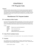
1
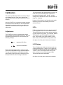
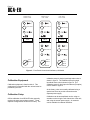
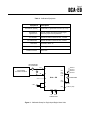
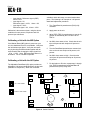
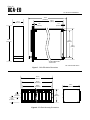
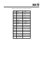
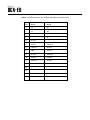
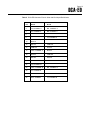
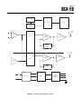
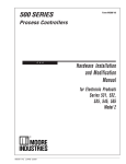
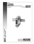
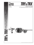
DCA-ED
Direct Current Alarm,
Eurocard-style with Display
USER’S MANUAL
May1990
© 1990 by Moore Industries-International, Inc.
No. 192-762-00B
Table of Contents
Introduction
1
Description
1
Calibration
3
Installation
9
Operation
9
Theory of Operation
14
Maintenance
14
Troubleshooting
14
HR.
Moore Industries’ STAR* Center has a
wide variety of quality instrumentation
in stock and ready to ship.
DELIVERY
8
4
UnitedStates/Canada
TOLLFREE
1-800-999-2900
United Kingdom
FREEPHONE
0800 525107
Australia
TOLLFREE
008 251928
• Signal Transmitters
• Temperature Transmitters
• P/I and I/P Converters
• Isolators and Converters
• Indicators and Displays
• Alarm Trips
• Integrators and Totalizers
• Power Transducers
• Instrument Power Supplies
• Racks, Rails and Enclosures
16650 Schoenborn Street
Sepulveda, California 91343, U.S.A.
Tel: (818) 894-7111 • Tlx: 65-1322
FAX: (818) 891-3297
CONNECT (MacNet): MIISEPULVEDA
Most instruments can be customized
to meet your needs. Even then, you’ll
never have to wait more than a few days.
18 Royce Road, Crawley
W. Sussex RH10-2NX, United Kingdom
Tel: 0293 514488 • Tlx: 87667
FAX: 0293 36852
Moore Industries
3/18 Resolution Drive, Caringbah
New South Wales 2229, Australia
Tel: (02) 525-9177 • Tlx: 790-75914
FAX: (02) 525-7296
CENTER
* Support, Technical Assistance, and Repair (our Quick-Ship Facility)
Ask for the STAR Center
i
DCA-ED
Page 1
Introduction
This manual contains descriptive, calibration, and
maintenance information on the Direct Current Alarm,
Eurocard-style with Display (DCA-ED). The DCA-ED
accepts all standard process inputs and produces a
signal that operates an alarm system. The DCA-ED
may be configured as a single alarm with one relay, a
dual alarm with two relays operating from one input
signal, or dual input (two isolated channels operating
independently from two inputs).
Each relay has an LED indicator in series, which
indicates when the relay is energized. The unit
operates in fail-safe mode; the relay is energized in
the normal condition and is de-energized under alarm
conditions or power loss.
Description
The DCA-ED is a 4-wire alarm unit on a Eurocard.
The unit features an LCD display in 0.25-inch high
black numerals over a reflective background. There
are 3-1/2 active digits with a decimal point and minus
sign to show ranges from -199.9 to +199.9. The
display shows the trip point value and input value as a
percent of span. These values are switch-selectable
by a rotary switch on the front panel of the unit.
The main board of the DCA-ED is divided into two
identical halves (channels) with separate power
supplies. A single alarm uses only one channel
(single input, single output). A dual alarm uses both
channels, with the inputs cross-linked (single input,
dual output). For a dual-input unit, both channels
operate independently without crosslinking. This
provides two single alarms on one board (dual input,
dual output).
The dual input (DI option) unit has two channels: A
and B. Channel A is normally set to the higher trip
point, but both channels are totally interchangeable.
A complete set of specifications for the DCA-ED is
shown in table 1. This specification contains complete information on input, output and performance.
Model Number. Moore Industries' model numbers
identify the type of instrument, functional characteristics, operating parameters, any options ordered, and
housing. If all accompanying documentation of a unit
is missing, the model number can be used to obtain
technical information. The model number for the
DCA-ED is located on the plug-in connector.
Serial Number. A complete history is kept on every
Moore Industries' unit. This information is keyed to
the serial number. Whenever service data is required
on a unit, it is necessary to provide the factory with
the serial number. This information is engraved on
the printed circuit board of the unit.
HIGH ALARM
100%
Analog
Value
TRIP POINT
DEAD BAND
RESET
0%
SAFE STATE
RELAY ENERGIZED, LED ON
RELAY DE-ENERGIZED, LED OFF
LOW ALARM
100%
Two slide-switches on the printed circuit board allow
each channel to be set to a high or a low alarm (both
fail-safe). Trip point controls allow the alarm to be
set to trip at any point over the input range. Trip point
potentiometers are provided to set the point at which
each of the alarm relays change state. With a high
alarm, the relay is de-energized when the input signal
is above the trip point. The relay is de-energized
when the input signal is below the trip point for a low
alarm. See figure 1.
ALARM STATE
Analog
Value
0%
SAFE STATE
RESET
DEAD BAND
TRIP POINT
ALARM STATE
Figure 1. High and Low Alarm Configurations
DCA-ED
Page 2
Table 1. DCA-ED Specifications
Characteristic
Input
Output
Input Power
Performance
Controls
Operating
Temperature
Feature
Display
Specification
Current:
1-5 mA @ 200-ohm nominal input impedance
4-20 mA @ 50-ohm nominal input impedance
10-50 mA @ 20-ohm nominal input impedance
0-20 mA @ 50-ohm nominal input impedance
Voltage: Input impedance 1 Mý, minimum; 200 Ký with DA or
ATL option
0-5 V, 1-5 V, 0.25-1.25 V, 0-1 V
1 or 2 DPDT relay contacts rated @ 5 A, 117 Vac non-inductive or 28 Vdc
TXA Output: 25 mA @ 24 Vdc, ±5%
TXB Output: 25 mA @ 24 Vdc ±5%
24 Vdc ±10%, 5 watts, nominal
Repeatability: Trip point repeats within ±0.1% of full span
Dead band: 1% of span, standard
Response: 150 milliseconds for a step change of 1% of span beyond
trip points
Line Voltage Effect: ±0.005% / 1% line change
Set Point: Multiturn potentiometer adjustable over 0-100% of span
Dead Band: Externally adjustable dead band 1-20% of span, nominal
Selection Switch: Enables User to display input or trip point value
Range: -18 to 65 °C (0 to 150 °F)
Effect: Less than ±0.018% / °C (±0.01% / °F) over above range
Relay status: LEDs light when relays are energized; switchselectable for high/low status
Shows trip point value and input value as a percentage of span;
switch-selectable
Type: LCD, 0.25-inch high black numerals over reflective background
Format: 3-1/2 digits
Range: -199.9 to +199.9
Decimal point: One
Rate: Two readings per second
Resolution: 0.1% ±1 LSD
DCA-ED
Page 3
Calibration
This section provides information necessary to adjust
and calibrate the unit. Each unit is adjusted and
checked at the factory for proper performance before
shipping.
After the DCA-ED unit is unpacked, general operation
level checks of the individual unit are recommended.
Generally, these checks, which are specified in the
Calibration Procedures Section, require little or no
adjustments.
Adjustments
The DCA-ED has trip point and dead band adjustments located on the front panel of the unit. They are
represented symbolically on the front panel by the
following markings:
The potentiometers are equipped with a slip clutch at
each end to prevent damage if the adjustment is
turned beyond the wiper stop. Usually, a slight
change can be felt when the clutch is at the end of a
range (i.e., slipping).
However, if this change is not felt, either end can be
reached by turning the shaft twenty turns in the
desired direction.
LEDs
LEDs associated with each output relay are included
on the front panel of the unit as a standard feature.
These LEDs inform the user when an alarm condition
or power failure has occurred. The LEDs are labeled
TRIP POINT A and TRIP POINT B on dual input
units, TRIP POINT A and TRIP POINT B on dual
alarm units, and TRIP POINT for single alarm units.
See figure 2 for front panel controls and indicators.
represents Trip Point
LCD Display
represents Dead Band
Each of these adjustments has a multiturn potentiometer that is adjustable using a slotted screwdriver.
The type of potentiometer used with these adjustments usually require 20 turns of the shaft to move
the wiper from one end of its range to the other.
The LCD display has 0.25-inch black numerals over
a reflective background. There are 3-1/2 digits with
a decimal point and minus sign to show ranges from
-199.9 to +199.9. The display shows the trip point
value and input value as a percentage of span.
These values are switch-selectable.
See figure 2 for front panel controls and indicators.
DCA-ED
Page 4
SX
SINGLE INPUT/
SINGLE ALARM
DX
SINGLE INPUT/
DUAL ALARM
TRIP POINT
76.8
%
TRIP
INPUT
TRIP POINT A
89.4
DI
DUAL INPUT/
DUAL ALARM
TRIP POINT A
42.3
%
%
TRIP POINT B
TRIP POINT B
TRIP A
INPUT
TRIP A
IN A
IN B
TRIP B
TRIP B
Figure 2. Front Panel Controls and Indicators, All Models
.
Calibration Equipment
Calibration equipment is listed in table 2. This
equipment is not supplied with the unit and must be
provided by the user.
Calibration Setup
Off-line calibration for all DCA-ED units generally
requires the same test equipment setup. Three
separate configurations are shown for clarity. The
calibration setup for single input/single alarm units is
shown in figure 3. The calibration setup for single
input/dual alarm units is shown in figure 4. The
calibration setup for dual input dual alarms (DI option)
units is shown in figure 5.
At the factory, units are normally calibrated using a
special test fixture to provide connection and a
separate power supply.
Calibration can be accomplished on-site, using an
extender card to bring the unit forward out of the rack,
and using the normal power supply. An extender
card is available from Moore Industries.
DCA-ED
Page 5
Table 2. Calibration Equipment
Equipment
Screwdriver (slotted)
Description
Head width no greater than 2.54 mm (0.1 inch)
Adjustable dc
signal source
Must be capable of producing signal ranges
defined by input level requirements
Dc voltmeter
Must be accurate to within ±0.05%, or better
Dc milliammeter
Must be accurate to within ±0.05%, or better
Ohmmeter
Power supply
Female connector
Accurate to within 1%
24 Vdc @ 1 A
DIN 41612
MILLIAMMETER
OR VOLTMETER
+ IN
M
ADJUSTABLE
DC SIGNAL SOURCE
Z12
Z10
D16
D14
V
– IN
– TX
NO K1/1
NC K1/1
NO K1/2
NC K1/2
Z2
Z4
D8
DCA – ED
M
Z14
D12
D4
– MR
COM K1/1
COM K1/2
Z16
D2
Z30
Z32
+ –
DC
OHMMETER
DCC
POWER INPUT
Figure 3. Calibration Setup for Single Input/Single Alarm Units
+ REF A (–DA)
DCA-ED
Page 6
FIG. 03 SI/DA
NO K2/2
NC K2/2
NO K2/1
NC K2/1
MILLIAMMETER
OR VOLTMETER
+ IN
M
ADJUSTABLE
DC SIGNAL SOURCE
Z2
V
– IN
– TX A
OHMMETER
M
COM K 2/2
COM K 2/1
D18
Z22
D20
D22
Z20
Z18
Z4
D8
NO K1/1
NC K1/1
NO K1/2
NC K1/2
Z12
Z10
D16
D14
M
DCA – ED
Z14
D12
D4
– MR
OHMMETER
COM K1/1
COM K1/2
D2
Z16
Z30
+
DC
+ REF A (–DA)
Z32
–
DCC
POWER INPUT
Figure 4. Calibration Setup for Single Input/Dual Alarm Units
Figure 5. Calibration Setup for Dual Input/Dual Alarm Units
DCA-ED
Page 7
Display Calibration Procedure
Calibration consists of simulating an input signal to
the DCA-ED, monitoring the input value on the LCD
display of the unit, and adjusting the controls to obtain
the desired value. Trip point settings are also set and
verified. The DCA-ED unit has an LCD display, which
shows the trip point value and input value as a
percent of span.
NOTE
For units configured with the DI option,
use the corresponding reference designation for DI, and repeat the test for the
B channel.
12. If the display does not read 100.0 percent, adjust
the display Span potentiometer, R6, for 100.0
percent.
13. For dual alarm units, set the input selector switch
to the blank position between input and TRIP B.
Adjust R51 for 100.0 percent on the display.
(DI=R51)
14. Repeat steps 8, 9 and 10 to verify a zero
percent input reading.
15. Apply 0, 25, 50 and 75 percent input.
1. Disconnect power from the EU-Rack.
16. Observe the LCD display at each setting in step
15 and verify that the input is linear for the
operating range selected.
2. Remove the DCA-ED to be calibrated from the
EU-Rack.
17. Turn the selector switch on the front of the unit to
TRIP A.
3. Insert the extender card into the Eurorack.
18. Set the TRIP A potentiometer (R102), located on
the front panel of the unit, to the desired trip point
value in percent of span.
4. Insert the DCA-ED into the extender card.
5. Verify that switches SW1 and SW2 (dual alarm)
are set for a high or low alarm, as specified. See
figure 6.
UP = high alarm
DOWN = low alarm
19. For dual alarm and DI units, repeat steps 17 and
18 for TRIP B potentiometer (R104).
6. Connect a precision signal source to the input of
the DCA-ED. Connect a 24 Vdc power source.
Refer to figures 3, 4 and 5.
The Alarm Response Delay (AR) option introduces a
time delay in the unit. This makes calibration difficult
because the user must wait for the delay time to see if
the setpoints have been tripped. The delay may be
defeated by short circuiting diodes CR4 and/or CR16.
Take extreme care in shorting diodes, as damage
may occur if diodes are accidentally shorted to other
parts.
7. Turn the selector switch to the INPUT position.
(DI=IN B)
8. Apply power to the unit and set the signal source
to an input equal to zero percent of the input
range.
Calibrating a Unit with AR Option
9. The display should read 000.0 percent.
Calibrating a Unit with the DA Option
10. If the display does not read 000.0 percent, adjust
the display Zero potentiometer, R109, for 000.0
percent. (DI=R112)
The Deviation Alarm (DA) option requires two inputs:
one reference signal and one input signal. The
deviation alarm detects any variation of the control
signal from the reference signal in either direction.
11. Adjust the signal source to 100 percent of the
input range.
DCA-ED
Page 8
1. Turn Dead Band A potentiometer (R103) fully
clockwise.
2. Apply power to the unit.
Calibration is the same as shown, using the above
conditions for zero percent, 50 percent and 100
percent input references.
3. Adjust TRIP (TRIP A) potentiometer to exactly 60
percent as indicated by the LCD when set to
TRIP A.
Calibrating a Unit with the MR Option
4. Set SW1 alarm status to low. Check that the unit
trips at 60 percent and untrips at 80 percent or
greater.
If the Manual Reset (MR) option is present on your
unit, the dead band circuit is not available. Verify that
the unit latches upon alarm. Verify the unit resets
only by shorting the MR terminals together with an
exernal switch after changing the input signal from
-25 to + 125%. Note: MR resets both alarms in a
dual alarm. For DI units MR is separate.
5. Turn the Dead Band potentiometer counterclockwise so the unit now untrips at 80 percent, ±0.1
percent.
6. Set SW1 alarm status to high. Check that the
unit trips at 60 percent and untrips at 40 percent,
±2 percent.
Calibrating a Unit with the AD Option
7. For dual alarm or DI units, repeat steps 1 through
6 for TRIP B potentiometer and Dead Band B
potentiometer (R105) using SW2.
SW1
1
R43
U2
R112
UP = HIGH ALARM
8
R106
R103
U1
CR4
R39
CR4
R6
R102
R109
The Adjustable Dead Band (AD) option provides an
adjustable 1-20 percent dead band from the trip point
(available to 100 percent). When the controlled
R36
CR16
K1
U3
DOWN = LOW ALARM
SW2
K2
T1
U4
Q5
Q6
Figure 6. Switch Positions
R101
R105
1
R98
8
R104
R96
•
R93
•
variable is within this range, no control action takes
place. The following is an example of a 20 percent
dead band adjustment procedure:
Input signal = Reference signal (+REF)
Alarm = 50%
Input signal = 0%
Reference signal = 100%, Alarm = 0%
Input signal = 100%
Reference signal = 0%, Alarm = 100%
R51
•
DCA-ED
Page 9
Any amount of dead band between 0.5 percent and
greater than 20 percent may be set using this procedure.
pending on the type of Eurocard selected. It is
available without a terminal block for applications
where terminal connectors (i.e., solder tags, wire
wrap pins, etc.) are used.
Completion of Calibration
Outline dimensions of the DCA-ED and the 19-inch
EU-Rack are shown in figures 7 and 8.
1. Remove power from the EU-Rack.
2. Disconnect the calibration equipment and reconnect the input leads.
3. Remove the extender card and the DCA-ED.
4. Replace the DCA-ED in the EU-Rack.
Electrical Connections
All electrical connections to the DCA-ED are made to
the terminals on the mating connector of the unit,
located in the rack. Refer to table 3, 4, or 5. The
terminals are designed for 16 AWG, maximum, wire
size.
5. Re-connect power to the EU-Rack.
Installation
This section contains physical mounting dimensions
and electrical connections for the DCA-ED. Although
the units are designed to operate in free air at a high
ambient temperature, it is recommended that if a
large number of units are mounted together in a rack
or cabinet, attention should be given to adequate
ventilation. In addition, input and output values
should be checked, on-site, before the unit is placed
into service.
Mounting
The DCA-ED is a plug-in card that mounts in a rack.
Moore Industries' EU-Rack is designed for highdensity mounting of Moore Industries' Eurocards.
Up to 12 individual cards can be installed in this
standard 19-inch rack.
The EU-Rack has 16-point screw connectors or 32point screw connectors on the terminal block, de-
The DCA-ED operates directly from a 24 Vdc power
source. The dc power source should be regulated to
within ±10 percent of the nominal voltage and should
be capable of delivering 5 watts.
Operation
Once the DCA-ED has been calibrated and installed,
it may be left unattended. The only controls for the
unit are the Setpoint and Dead Band potentiometers,
which after initial adjustment require no further
attention.
The LEDs on the front of the unit indicate when an
alarm is energized. Because the circuit uses highly
reliable solid-state components with no moving parts,
the DCA-ED operates maintenance-free for extended
periods of time.
The DCA-ED may become warm during operation,
especially when a large number of cards are mounted
together in a rack or cabinet, and the ambient temperature is above normal. This is perfectly acceptable and should not be cause for alarm, unless a
malfunction is also observed.
DCA-ED
Page 10
FIG. 06 DCA-EU DIMENSION
7.50 in
(190.5mm)
1.37 in
(35.3mm)
6.30 in
(160mm)
.14 in
(3.57mm)
.11 in
(2.76mm)
5.06 in
(128.4mm)
3.50 in
(88.9mm)
3.94 in
(100mm)
32 PIN CONNECTOR
TO DIN 41612
FIG. 07 EUROCARD RACK
Figure 7. DCA-ED Outline Dimensions
19.01 in
(483mm)
18.31 in
(465.10mm)
8.13 in
(206.5mm)
16.80 in
(426.70mm)
2.25 in
(57.10mm)
5.22 in
(132.5mm)
1.48 in
(37.70mm)
Figure 8. EU-Rack Mounting Dimensions
DCA-ED
Page 11
Table 3. DCA-ED Connector Pins for Units with Single Alarm
Pin
Row Z
Row D
2
+IN
MR
4
-IN
MR
6
8
TXA
10
NC K1/1
12
NO K1/1
COM K1/2
14
COM K1/1
NC K1/2
16
+REF
NO K1/2
18
20
22
24
26
28
30
DC +24
32
DCC COMMON
DCA-ED
Page 12
Table 4. DCA-ED Connector Pins for Units with Single Input/Dual Alarms
Pin
Row Z
Row D
2
+IN
MR
4
-IN
MR
6
8
TX
10
NC K1/1
12
NO K1/1
COM K1/2
14
COM K1/1
NC K1/2
16
+REF
NO K1/2
18
NC K2/1
COM K2/2
20
NO K2/1
NO K2/2
22
COM K2/1
NC K2/2
24
26
28
30
DC +24
32
DCC COMMON
DCA-ED
Page 13
Table 5. DCA-ED Connector Pins for Units with Dual Input/Dual Alarms
Pin
Row Z
Row D
2
+IN, CHANNEL A
MR , CHANNEL A
4
-IN, CHANNEL A
MR, CHANNEL A
6
8
TX, CHANNEL A
10
NC K1/1
12
NO K1/1
COM K1/2
14
COM K1/1
NC K1/2
16
+REF, CHANNEL A
NO K1/2
18
NC K2/1
COM K2/2
20
NO K2/1
NO K2/2
22
COM K2/1
NC K2/2
24
+IN, CHANNEL B
26
+REF, CHANNEL B
28
-IN, CHANNEL B
30
DC +24
MR, CHANNEL B
32
DCC COMMON
TX, CHANNEL B
MR , CHANNEL B
DCA-ED
Page 14
Theory of Operation
Maintenance
This section describes the unit operation. The
functional description is based on the block diagram
in figure 9.
Maintenance of the DCA-ED is limited to keeping the
terminals clean and tight, and ensuring there is
adequate ventilation or heat dissipation for the unit.
It is recommended that the user check the terminals
every six months.
Power Supply Circuit
Units are supplied for use with a dc power input that
is applied directly to the power inverter, with diode
protection to prevent damage to the power inverter if
the dc power input is accidentally connected with
reverse polarity.
Manual Reset
The manual reset option configures U2 and U3 such
that they latch in an alarm condition. An additional
input is provided (external contact closure) to overcome the latched condition of U2 and U3 when the
input returns to normal.
Adjustable Dead Band
The adjustable dead band circuit adjusts the hysteresis between the trip point and reset points. The adjustment is available for both single and dual alarm
units. The dead band is adjusted by the potentiometer(s) on the front of the unit. After the trip point
has occurred, the affect of the inverting input (pin 9)
on amplifier output (pin 8) occurs only after the noninverting amplifier input (pin 10) is overcome. The
Dead Band potentiometer varies this non-inverting
amplifier input level by adjusting the amount of
feedback to pin 10. The Dead Band potentiometer
varies the difference between the trip point and reset
point within the signal span. The greater amount
of feedback to pin 10, the greater the dead band.
Troubleshooting
Troubleshooting the DCA-ED involves determining
whether the unit is functioning abnormally. The
calibration equipment listed in table 2 can be used to
verify that the DCA-ED outputs are within specified
limits (refer to specifications, table 1). It is recommended that any unit found performing below specifications be returned to the factory for service in
accordance with the instructions on the back cover of
this manual.
If a problem is suspected with the DCA-ED, it is
suggested that the following check list be reviewed as
a preliminary step:
1. Verify that all electrical connections are clean and
tight.
2. Verify that the measuring instrument used for
input voltage or current is of the proper range and
accuracy.
3. Verify that the output circuit is electrically isolated
from the input circuit.
If a unit is performing below specifications, and the
unit cannot immediately be sent back to the factory
without affecting operations, contact Moore Industries'
Customer Service Department toll free at 1-800-9992900.
DCA-ED
Page 15
Power Supply
A/D Converter
Display
Input and Offset
Circuit
+
Output
Relay
+ In
Input Buffer
Latch and
Comparator
Upper
- In
Relay Driver
Adjustable
Feedback
(Ad Option)
+
Dual Trip Unit
Output
Relay
Latch and
Comparator
Lower
Relay Driver
Input Buffer
Adjustable
Feedback
(Ad Option)
DC
Power Inverter
Rectifier
Voltage
Regulator and
Rectifier
DC Power
Figure 9. DCA-ED Simplified Block Diagram
RETURN PROCEDURES
To return equipment to Moore Industries for repair, follow these four steps:
1. Call Moore Industries and request a Returned Material Authorization (RMA) number.
Warranty Repair –
If you are unsure if your unit is still under warranty, we can use the unit’s serial number
to verify the warranty status for you over the phone. Be sure to include the RMA
number on all documentation.
Non-Warranty Repair –
If your unit is out of warranty, be prepared to give us a Purchase Order number when
you call. In most cases, we will be able to quote you the repair costs at that time.
The repair price you are quoted will be a “Not To Exceed” price, which means that the
actual repair costs may be less than the quote. Be sure to include the RMA number on
all documentation.
2. Provide us with the following documentation:
a) A note listing the symptoms that indicate the unit needs repair
b) Complete shipping information for return of the equipment after repair
c) The name and phone number of the person to contact if questions arise at the factory
3. Use sufficient packing material and carefully pack the equipment in a sturdy shipping
container.
4. Ship the equipment to the Moore Industries location nearest you.
The returned equipment will be inspected and tested at the factory. A Moore Industries
representative will contact the person designated on your documentation if more information is
needed. The repaired equipment, or its replacement, will be returned to you in accordance with
the shipping instructions furnished in your documentation.
WARRANTY DISCLAIMER
THE COMPANY MAKES NO EXPRESS, IMPLIED OR STATUTORY WARRANTIES (INCLUDING ANY WARRANTY OF MERCHANTABILITY OR OF FITNESS
FOR A PARTICULAR PURPOSE) WITH RESPECT TO ANY GOODS OR SERVICES SOLD BY THE COMPANY. THE COMPANY DISCLAIMS ALL WARRANTIES ARISING FROM ANY COURSE OF DEALING OR TRADE USAGE, AND
ANY BUYER OF GOODS OR SERVICES FROM THE COMPANY ACKNOWLEDGES THAT THERE ARE NO WARRANTIES IMPLIED BY CUSTOM OR
USAGE IN THE TRADE OF THE BUYER AND OF THE COMPANY, AND THAT
ANY PRIOR DEALINGS OF THE BUYER WITH THE COMPANY DO NOT IMPLY THAT THE COMPANY WARRANTS THE GOODS OR SERVICES IN ANY
WAY.
ANY BUYER OF GOODS OR SERVICES FROM THE COMPANY AGREES
WITH THE COMPANY THAT THE SOLE AND EXCLUSIVE REMEDIES FOR
BREACH OF ANY WARRANTY CONCERNING THE GOODS OR SERVICES
SHALL BE FOR THE COMPANY, AT ITS OPTION, TO REPAIR OR REPLACE
THE GOODS OR SERVICES OR REFUND THE PURCHASE PRICE. THE
COMPANY SHALL IN NO EVENT BE LIABLE FOR ANY CONSEQUENTIAL OR
INCIDENTAL DAMAGES EVEN IF THE COMPANY FAILS IN ANY ATTEMPT
TO REMEDY DEFECTS IN THE GOODS OR SERVICES , BUT IN SUCH CASE
THE BUYER SHALL BE ENTITLED TO NO MORE THAN A REFUND OF ALL
MONIES PAID TO THE COMPANY BY THE BUYER FOR PURCHASE OF THE
GOODS OR SERVICES.
United States • [email protected]
Tel: (818) 894-7111 • FAX: (818) 891-2816
Australia • [email protected]
Tel: (02) 8536-7200 • FAX: (02) 9525-7296
© 2007 Moore Industries-International, Inc.
ANY CAUSE OF ACTION FOR BREACH OF ANY WARRANTY BY THE
COMPANY SHALL BE BARRED UNLESS THE COMPANY RECEIVES
FROM THE BUYER A WRITTEN NOTICE OF THE ALLEGED DEFECT OR
BREACH WITHIN TEN DAYS FROM THE EARLIEST DATE ON WHICH THE
BUYER COULD REASONABLY HAVE DISCOVERED THE ALLEGED DEFECT OR BREACH, AND NO ACTION FOR THE BREACH OF ANY WARRANTY SHALL BE COMMENCED BY THE BUYER ANY LATER THAN
TWELVE MONTHS FROM THE EARLIEST DATE ON WHICH THE BUYER
COULD REASONABLY HAVE DISCOVERED THE ALLEGED DEFECT OR
BREACH.
RETURN POLICY
For a period of thirty-six (36) months from the date of shipment, and under
normal conditions of use and service, Moore Industries ("The Company") will
at its option replace, repair or refund the purchase price for any of its manufactured products found, upon return to the Company (transportation charges
prepaid and otherwise in accordance with the return procedures established
by The Company), to be defective in material or workmanship. This policy
extends to the original Buyer only and not to Buyer's customers or the users
of Buyer's products, unless Buyer is an engineering contractor in which case
the policy shall extend to Buyer's immediate customer only. This policy shall
not apply if the product has been subject to alteration, misuse, accident, neglect or improper application, installation, or operation. THE COMPANY
SHALL IN NO EVENT BE LIABLE FOR ANY INCIDENTAL OR CONSEQUENTIAL DAMAGES.
Belgium • [email protected]
Tel: 03/448.10.18 • FAX: 03/440.17.97
The Netherlands • [email protected]
Tel: (0)344-617971 • FAX: (0)344-615920
China • [email protected]
Tel: 86-21-62491499 • FAX: 86-21-62490635
United Kingdom • [email protected]
Tel: 01293 514488 • FAX: 01293 536852
Specifications and Information subject to change without notice.