1
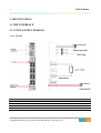
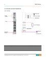
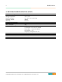
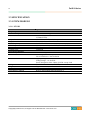
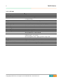
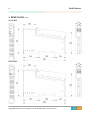
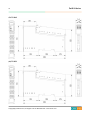
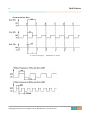
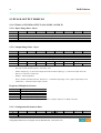
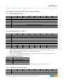
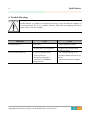
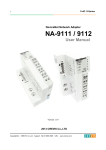
1 FnIO S-Series PWM & Pulse Output (Pulse Width Modulation) PWM: ST-5422 Pulse: ST-5641 ST-5442 ST-5642 ST-5444 ST-5651 User Manual Version 1.03 2013 CREVIS Co.,Ltd Copyright(C) CREVIS Co.,Ltd Support +82-31-899-4599 URL: www.crevis.co.kr 2 FnIO S-Series DOCUMENT CHANGE SUMMARY REV PAGE 1.0 New Document 1.01 6 REMARKS DATE EDITOR Draft 2010/12/6 JE KANG Add your experience 2012/1/13 JE KANG 1.02 Changed Crevis TEL 2013/4/4 JE KANG 1.03 Environment Spec. 50℃→55℃ (UL Temp) 2013/7/3 JE Kang Copyright(C) CREVIS Co.,Ltd Support +82-31-899-4599 URL: www.crevis.co.kr 3 FnIO S-Series Table of Contents 1. Important Notes ............................................................................................................................................ 6 1.1 Safety Instruction ................................................................................................................................... 7 1.1.1 Symbols............................................................................................................................................... 7 1.1.2 Safety Notes ..................................................................................................................................... 7 1.1.3 Certification ....................................................................................................................................... 7 2. MODULE LIST ................................................................................................................................................. 8 2.1 PWM OUTPUT MODULE LIST ........................................................................................................... 8 2.2 PULSE OUTPUT MODULE LIST ......................................................................................................... 8 3. SPECIFICATION ............................................................................................................................................... 9 3.1 THE INTERFACE ....................................................................................................................................... 9 3.1.1 PWM OUTPUT MODULE ............................................................................................................. 9 3.1.1.1 ST-5422 ....................................................................................................................................... 9 3.1.1.2 ST-5442 .................................................................................................................................... 10 3.1.1.3 ST-5444 .................................................................................................................................... 11 3.1.2 PULSE OUTPUT MODULE ......................................................................................................... 12 3.1.2.1 ST-5641 .................................................................................................................................... 12 3.1.2.2 ST-5642 .................................................................................................................................... 13 3.1.2.3 ST-5651 .................................................................................................................................... 14 3.2 ENVIRONMENT SPECIFICATION ................................................................................................... 15 3.3 SPECIFICATION ..................................................................................................................................... 16 3.3.1 PWM MODULE ............................................................................................................................. 16 3.3.1.1 ST-5422 .................................................................................................................................... 16 3.3.1.2 ST-5442 .................................................................................................................................... 17 Copyright(C) CREVIS Co.,Ltd Support +82-31-899-4599 URL: www.crevis.co.kr 4 FnIO S-Series 3.3.1.3 ST-5444 .................................................................................................................................... 18 3.3.2 PULSE MODULE............................................................................................................................ 19 3.3.2.1 ST-5641 .................................................................................................................................... 19 3.3.2.1 ST-5642 .................................................................................................................................... 20 3.3.2.1 ST-5651 .................................................................................................................................... 21 4. DIMENSION .................................................................................................................................................. 22 5. CONFIGURATION AND OPERATIONAL FUNCTION..................................................................... 25 5.1 PWM OUTPUT MODULE .................................................................................................................. 25 5.1.1 ST-5422 ( 2 CH PWM OUTPUT, 1.5A/24VDC, SOURCE ) ........................................... 25 5.1.1.1 Input Image Data - 2byte ................................................................................................ 25 5.1.1.2 Output Image Data - 6byte ............................................................................................ 25 5.1.1.3 Configuration Parameter Data ....................................................................................... 25 5.1.2 ST-5442 ( 2 CH PWM OUTPUT, 0.5A/24VDC, SOURCE ) ........................................... 27 5.1.2.1 Input Image Data - 2byte ................................................................................................ 27 5.1.2.2 Output Image Data - 6byte ............................................................................................ 27 5.1.2.3 Configuration Parameter Data ....................................................................................... 27 5.1.3 ST-5444 ( 4 CH PWM OUTPUT, 0.5A/24VDC, SOURCE ) ........................................... 28 5.1.3.1 Input Image Data - 4byte ................................................................................................ 28 5.1.3.2 Output Image Data - 12byte ......................................................................................... 28 5.1.3.3 Configuration Parameter Data ....................................................................................... 28 5.2 PULSE OUTPUT MODULE ................................................................................................................ 29 5.2.1 ST-5641 ( 1 CH PWM OUTPUT, 0.5A/24VDC, SOURCE ) ........................................... 29 5.2.1.1 Input Image Data - 4byte ................................................................................................ 29 5.2.1.2 Output Image Data - 6byte ............................................................................................ 29 Copyright(C) CREVIS Co.,Ltd Support +82-31-899-4599 URL: www.crevis.co.kr 5 FnIO S-Series 5.2.1.3 Configuration Parameter Data ....................................................................................... 29 5.2.2 ST-5642 ( 2 CH PWM OUTPUT, 0.5A/24VDC, SOURCE ) ........................................... 30 5.2.2.1 Input Image Data - 8byte ................................................................................................ 30 5.2.2.2 Output Image Data - 10byte ......................................................................................... 30 5.2.2.3 Configuration Parameter Data ....................................................................................... 30 5.2.3 ST-5651 ( 1 CH PWM OUTPUT, 0.5A/24VDC, SOURCE ) ........................................... 31 5.2.3.1 Input Image Data - 4byte ................................................................................................ 31 5.2.3.2 Output Image Data - 6byte ............................................................................................ 31 5.2.3.3 Configuration Parameter Data ....................................................................................... 31 6. Trouble Shooting........................................................................................................................................ 32 Copyright(C) CREVIS Co.,Ltd Support +82-31-899-4599 URL: www.crevis.co.kr 6 FnIO S-Series 1. Important Notes Solid state equipment has operational characteristics differing from those of electromechanical equipment. Safety Guidelines for the Application, Installation and Maintenance of Solid State Controls describes some important differences between solid state equipment and hard-wired electromechanical devices. Because of this difference, and also because of the wide variety of uses for solid state equipment, all persons responsible for applying this equipment must satisfy themselves that each intended application of this equipment is acceptable. In no event will CREVIS be responsible or liable for indirect or consequential damages resulting from the use or application of this equipment. The examples and diagrams in this manual are included solely for illustrative purposes. Because of the many variables and requirements associated with any particular installation, CREVIS cannot assume responsibility or liability for actual use based on the examples and diagrams. Warning! If you don’t follow the directions, it could cause a personal injury, damage to the equipment or explosion Do not assemble the products and wire with power applied to the system. Else it may cause an electric arc, which can result into unexpected and potentially dangerous action by field devices. Arching is explosion risk in hazardous locations. Be sure that the area is non-hazardous or remove system power appropriately before assembling or wiring the modules. Do not touch any terminal blocks or IO modules when system is running. Else it may cause the unit to an electric shock or malfunction. Keep away from the strange metallic materials not related to the unit and wiring works should be controlled by the electric expert engineer. Else it may cause the unit to a fire, electric shock or malfunction. Caution! If you disobey the instructions, there may be possibility of personal injury, damage to equipment or explosion. Please follow below Instructions. Check the rated voltage and terminal array before wiring. Avoid the circumstances over 55℃ of temperature. Avoid placing it directly in the sunlight. Avoid the place under circumstances over 85% of humidity. Do not place Modules near by the inflammable material. Else it may cause a fire. Do not permit any vibration approaching it directly. Go through module specification carefully, ensure inputs, output connections are made with the specifications. Use standard cables for wiring. Use Product under pollution degree 2 environment. Copyright(C) CREVIS Co.,Ltd Support +82-31-899-4599 URL: www.crevis.co.kr 7 FnIO S-Series 1.1 Safety Instruction 1.1.1 Symbols Identifies information about practices or circumstances that can cause an explosion in a hazardous environment, which may lead to personal injury or death property damage, or economic loss. Identifies information that is critical for successful application and understanding of the product Identifies information about practices or circumstances that can lead to personal injury, property damage, or economic loss. Attentions help you to identity a hazard, avoid a hazard, and recognize the consequences 1.1.2 Safety Notes The modules are equipped with electronic components that may be destroyed by electrostatic discharge. When handling the modules, ensure that the environment (persons, workplace and packing) is well grounded. Avoid touching conductive components, e.g. FnBUS Pin. 1.1.3 Certification c-UL-us UL Listed Industrial Control Equipment, certified for U.S. and Canada See UL File E235505 DNV CERTIFICATE No. A-10666 CE Certificate EN 61000-6-2; Industrial Immunity EN 61000-6-4; Industrial Emissions Copyright(C) CREVIS Co.,Ltd Support +82-31-899-4599 URL: www.crevis.co.kr 8 FnIO S-Series 2. MODULE LIST 2.1 PWM OUTPUT MODULE LIST ST-Number ST-5422 ST-5442 ST-5444 Description ID(hex) 2 CH PWM OUTPUT, 1.5A/24VDC, SOURCE 2 CH PWM OUTPUT, 0.5A/24VDC, SOURCE 4 CH PWM OUTPUT, 0.5A/24VDC, SOURCE 57 56 54 Production status Active Active Active 2.2 PULSE OUTPUT MODULE LIST ST-Number ST-5641 ST-5642 ST-5651 Description ID(hex) 1 CH Pulse OUTPUT, 0.5A/24VDC, SOURCE 2 CH Pulse OUTPUT, 0.5A/24VDC, SOURCE 1 CH Pulse OUTPUT, RS422 92 90 98 Copyright(C) CREVIS Co.,Ltd Support +82-31-899-4599 URL: www.crevis.co.kr Production status Active Active Active 9 FnIO S-Series 3. SPECIFICATION 3.1 THE INTERFACE 3.1.1 PWM OUTPUT MODULE 3.1.1.1 ST-5422 Pin No. 0 2 4 6 Description PWM Output Channel #0 --Field Power 0V, Common Field Power 24V Pin No. 1 3 5 7 Description PWM Output Channel #1 --Field Power 0V, Common Field Power 24V Copyright(C) CREVIS Co.,Ltd Support +82-31-899-4599 URL: www.crevis.co.kr 10 FnIO S-Series 3.1.1.2 ST-5442 Pin No. 0 2 4 6 Description PWM Output Channel #0 --Field Power 0V, Common Field Power 24V Pin No. 1 3 5 7 Description PWM Output Channel #1 --Field Power 0V, Common Field Power 24V Copyright(C) CREVIS Co.,Ltd Support +82-31-899-4599 URL: www.crevis.co.kr 11 FnIO S-Series 3.1.1.3 ST-5444 Pin No. 0 2 4 6 Description PWM Output Channel #0 PWM Output Channel #2 Field Power 0V, Common Field Power 24V Pin No. 1 3 5 7 Description PWM Output Channel #1 PWM Output Channel #3 Field Power 0V, Common Field Power 24V Copyright(C) CREVIS Co.,Ltd Support +82-31-899-4599 URL: www.crevis.co.kr 12 FnIO S-Series 3.1.2 PULSE OUTPUT MODULE 3.1.2.1 ST-5641 Pin No. 0 2 4 6 Description Pulse Output Channel #0 --Field Power 0V, Common Field Power 24V Pin No. 1 3 5 7 Description Pulse Direction Output Channel #0 --Field Power 0V, Common Field Power 24V Copyright(C) CREVIS Co.,Ltd Support +82-31-899-4599 URL: www.crevis.co.kr 13 FnIO S-Series 3.1.2.2 ST-5642 Pin No. 0 2 4 6 Description Pulse Output Channel #0 Pulse Output Channel #1 Field Power 0V, Common Field Power 24V Pin No. 1 3 5 7 Description Pulse Direction Output Channel #0 Pulse Direction Output Channel #1 Field Power 0V, Common Field Power 24V Copyright(C) CREVIS Co.,Ltd Support +82-31-899-4599 URL: www.crevis.co.kr 14 FnIO S-Series 3.1.2.3 ST-5651 Pin No. 0 2 4 6 Description Pulse+ (RS422 Differential Output) Direction+ (RS422 Differential Output) ---Field Power 24V Pin No. 1 3 5 7 Description Pulse- (RS422 Differential Output) Direction- (RS422 Differential Output) Shield Field Power 0V, Common Copyright(C) CREVIS Co.,Ltd Support +82-31-899-4599 URL: www.crevis.co.kr 15 FnIO S-Series 3.2 ENVIRONMENT SPECIFICATION Environmental Specifications Operating Temperature Storage Temperature Relative Humidity Operating Altitude Mounting -20℃~55℃ -40℃~85℃ 5% ~ 90% non-condensing 2000m DIN rail General Specifications Shock Operating Shock Non-Operating Vibration/Shock resistance 10g 30g Displacement : 0.012Inch p-p from 10~57Hz Acceleration : 2G’s from 57~500Hz Sweep Rate : 1 octave Per Minute Axes to test : x, y, z Frequency Sweeps Per Axis : 10 EMC resistance burst/ESD Installation Pos. / Protect. Class Product Certifications EMC Directive Variable/IP20 UL/cUL, CE Copyright(C) CREVIS Co.,Ltd Support +82-31-899-4599 URL: www.crevis.co.kr 16 FnIO S-Series 3.3 SPECIFICATION 3.3.1 PWM MODULE 3.3.1.1 ST-5422 Items Output Specification Number of Outputs Indicators Output Current Output Inrush Current PWM Frequency PWM Duty Diagnostic Common Type General Specification Power Dissipation Isolation Field Power Wiring Weight Module Size Environment Condition Specification 2 Channel, Source Type 1 Green/Red FnBus Status 2 Channel LEDs 1.5A/Ch, 3A/All Channel, short protection. Max. 2A, 100ms / Ch 1~2500Hz±0.5% 0.0~100.0%±1.0% (0.1%/1LSB), Ton>5us, Toff>5us Short Protection 2Common Max. 150mA @5.0Vdc I/O to Logic : Photocoupler Isolation I/O to Field Power : Non-Isolation Supply Voltage : 24Vdc nominal Voltage Range : 18~28.8Vdc Power Dissipation: Max. 50mA @24Vdc except Load I/O Cable Max. 2.0mm²(AWG#14) 70g 12mm x 99mm x 70mm Refer to Environment Specification.(p13) Copyright(C) CREVIS Co.,Ltd Support +82-31-899-4599 URL: www.crevis.co.kr 17 FnIO S-Series 3.3.1.2 ST-5442 Items Output Specification Number of Outputs Indicators Output Current Output Inrush Current PWM Frequency PWM Duty Diagnostic Common Type General Specification Power Dissipation Isolation Field Power Wiring Weight Module Size Environment Condition Specification 2 Channel, Source Type 1 Green/Red FnBus Status 2 Channel LEDs 0.5A/Ch, 2A/All Channel, short protection. Max. 1.5A, 100ms / Ch 1~2500Hz±0.5% 0.0~100.0%±1.0% (0.1%/1LSB), Ton>5us, Toff>5us Short Protection 2Common Max. 150mA @5.0Vdc I/O to Logic : Photocoupler Isolation I/O to Field Power : Non-Isolation Supply Voltage : 24Vdc nominal Voltage Range : 18~28.8Vdc Power Dissipation: Max. 50mA @24Vdc except Load I/O Cable Max. 2.0mm²(AWG#14) 70g 12mm x 99mm x 70mm Refer to Environment Specification.(p13) Copyright(C) CREVIS Co.,Ltd Support +82-31-899-4599 URL: www.crevis.co.kr 18 FnIO S-Series 3.3.1.3 ST-5444 Items Output Specification Number of Outputs Indicators Output Current Output Inrush Current PWM Frequency PWM Duty Diagnostic Common Type General Specification Power Dissipation Isolation Field Power Wiring Weight Module Size Environment Condition Specification 4 Channel, Source Type 1 Green/Red FnBus Status 4 Channel LEDs 0.5A/Ch, 2A/All Channel, short protection. Max. 1.5A, 100ms / Ch 1~2500Hz±0.5% 0.0~100.0%±1.0% (0.1%/1LSB), Ton>5us, Toff>5us Short Protection 2Common Max. 150mA @5.0Vdc I/O to Logic : Photocoupler Isolation I/O to Field Power : Non-Isolation Supply Voltage : 24Vdc nominal Voltage Range : 18~28.8Vdc Power Dissipation: Max. 50mA @24Vdc except Load I/O Cable Max. 2.0mm²(AWG#14) 70g 12mm x 99mm x 70mm Refer to Environment Specification.(p13) Copyright(C) CREVIS Co.,Ltd Support +82-31-899-4599 URL: www.crevis.co.kr 19 FnIO S-Series 3.3.2 PULSE MODULE 3.3.2.1 ST-5641 Items Output Specification Number of Channel Number of Output Indicators Output Current Pulse Output Frequency Pulse Output Duty Pulse Output Quantity with One Command Pulse Output Counter Diagnostic Common Type General Specification Power Dissipation Isolation Field Power Wiring Weight Module Size Environment Condition Specification 1 Channel, Source Type 2 Output/Channel 2 Output (1 Pulse Output, 1 Pulse Direction Output) 1 Green/Red FnBus Status 1 Pulse Output LED, 1Pulse Direction Output LED 0.5A/Output, 1A/All Output, short protection 1~20,000Hz±0.5% 50%±3.0% Fixed, Ton>5us, Toff>5us Continuous Pulse Output Max. +1~32767 : Pulse Direction Output OFF Max. -1~32767 : Pulse Direction Output ON Signed 32bit-wide Yes, Short Protection 2Common Max. 150mA @5.0Vdc I/O to Logic : Photocoupler Isolation I/O to Field Power : Non-Isolation Supply Voltage : 24Vdc nominal Voltage Range : 18~28.8Vdc Power Dissipation: Max. 60mA @24Vdc except Load I/O Cable Max. 2.0mm²(AWG#14) 70g 12mm x 99mm x 70mm Refer to Environment Specification.(p13) Copyright(C) CREVIS Co.,Ltd Support +82-31-899-4599 URL: www.crevis.co.kr 20 FnIO S-Series 3.3.2.1 ST-5642 Items Output Specification Number of Channel Number of Output Indicators Output Current Pulse Output Frequency Pulse Output Duty Pulse Output Quantity with One Command Pulse Output Counter Diagnostic Common Type General Specification Power Dissipation Isolation Field Power Wiring Weight Module Size Environment Condition Specification 2 Channel, Source Type 2 Output/Channel 4 Output (2 Pulse Output, 2 Pulse Direction Output) 1 Green/Red FnBus Status 2 Pulse Output LED, 2 Pulse Direction Output LED 0.5A/Output, 2A/All Output, short protection 1~20,000Hz±0.5% 50%±3.0% Fixed, Ton>5us, Toff>5us Continuous Pulse Output Max. +1~32767 : Pulse Direction Output OFF Max. -1~32767 : Pulse Direction Output ON Signed 32bit-wide Yes, Short Protection 2Common Max. 150mA @5.0Vdc I/O to Logic : Photocoupler Isolation I/O to Field Power : Non-Isolation Supply Voltage : 24Vdc nominal Voltage Range : 18~28.8Vdc Power Dissipation: Max. 60mA @24Vdc except Load I/O Cable Max. 2.0mm²(AWG#14) 70g 12mm x 99mm x 70mm Refer to Environment Specification.(p13) Copyright(C) CREVIS Co.,Ltd Support +82-31-899-4599 URL: www.crevis.co.kr 21 FnIO S-Series 3.3.2.1 ST-5651 Items Output Specification Number of Channel Number of Output Indicators Pulse Output Frequency Pulse Output Duty Pulse Output Quantity with One Command Pulse Output Counter Common Type General Specification Power Dissipation Isolation Field Power Wiring Weight Module Size Environment Condition Specification 1 Channel, RS422 Differential Output 2 Output (1 Pulse Output, 1 Pulse Direction Output) 1 Green/Red FnBus Status 1 Pulse Output LED, 1Pulse Direction Output LED 5~200,000Hz±1.0% 50%±0.1% Fixed, Ton>10us, Toff>10us Continuous Pulse Output Max. +1~32767 : Pulse Direction Output OFF Max. -1~32767 : Pulse Direction Output ON Signed 32bit-wide 1Common, 1 Shield Max. 150mA @5.0Vdc I/O to Logic : Photocoupler Isolation I/O to Field Power : Non-Isolation Supply Voltage : 24Vdc nominal Voltage Range : 11~28.8Vdc Power Dissipation: Max. 40mA @24Vdc I/O Cable Max. 2.0mm²(AWG#14) 70g 12mm x 99mm x 70mm Refer to Environment Specification.(p13) Copyright(C) CREVIS Co.,Ltd Support +82-31-899-4599 URL: www.crevis.co.kr 22 4. DIMENSION (mm) (1)ST-5422 (2)ST-5442 Copyright(C) CREVIS Co.,Ltd Support +82-31-899-4599 URL: www.crevis.co.kr FnIO S-Series 23 (3)ST-5444 (4)ST-5641 Copyright(C) CREVIS Co.,Ltd Support +82-31-899-4599 URL: www.crevis.co.kr FnIO S-Series 24 (5)ST-5642 (6)ST-5651 Copyright(C) CREVIS Co.,Ltd Support +82-31-899-4599 URL: www.crevis.co.kr FnIO S-Series 25 FnIO S-Series 5. CONFIGURATION AND OPERATIONAL FUNCTION 5.1 PWM OUTPUT MODULE 5.1.1 ST-5422 (2 CH PWM OUTPUT, 1.5A/24VDC, SOURCE) 5.1.1.1 Input Image Data - 2byte Byte Bit 7 Bit 6 Bit 5 0 1 Bit 4 Bit 3 Bit 2 Bit 1 Bit 0 Bit 2 Bit 1 Bit 0 Reserved Reserved 5.1.1.2 Output Image Data - 6byte Byte Bit 7 Bit 6 Bit 5 0 1 2 3 4 5 Bit 4 Bit 3 Frequency Ch#0,1 Low Byte Frequency Ch#0,1 High Byte Duty Ch#0 Low Byte Duty Ch#0 High Byte Duty Ch#1 Low Byte Duty Ch#1 High Byte - Ch#0, 1 is using the same frequency. - Range of each Duty is 0(0.0%) ~ 1000(100.0%). If Duty value is 250, then Duty rate is 25.0% 5.1.1.3 Configuration Parameter Data Byte 0 1 Bit 7 Bit 6 Bit 5 Bit 4 Bit 3 Reserved Reserved Copyright(C) CREVIS Co.,Ltd Support +82-31-899-4599 URL: www.crevis.co.kr Bit 2 Bit 1 Bit 0 26 FnIO S-Series *Compared Duty Rate T = Time (If Frequency = 10 KHz then T= 0.1ms) Copyright(C) CREVIS Co.,Ltd Support +82-31-899-4599 URL: www.crevis.co.kr 27 FnIO S-Series 5.1.2 ST-5442 (2 CH PWM OUTPUT, 0.5A/24VDC, SOURCE) 5.1.2.1 Input Image Data - 2byte Byte Bit 7 Bit 6 Bit 5 0 1 Bit 4 Bit 3 Bit 2 Bit 1 Bit 0 Bit 2 Bit 1 Bit 0 Reserved Reserved 5.1.2.2 Output Image Data - 6byte Byte Bit 7 Bit 6 Bit 5 0 1 2 3 4 5 Bit 4 Bit 3 Frequency Ch#0,1 Low Byte Frequency Ch#0,1 High Byte Duty Ch#0 Low Byte Duty Ch#0 High Byte Duty Ch#1 Low Byte Duty Ch#1 High Byte - Ch#0, 1 is using the same frequency. - Range of each Duty is 0(0.0%) ~ 1000(100.0%). If Duty value is 250, then Duty rate is 25.0% 5.1.2.3 Configuration Parameter Data Byte 0 1 Bit 7 Bit 6 Bit 5 Bit 4 Bit 3 Reserved Reserved Copyright(C) CREVIS Co.,Ltd Support +82-31-899-4599 URL: www.crevis.co.kr Bit 2 Bit 1 Bit 0 28 FnIO S-Series 5.1.3 ST-5444 (4 CH PWM OUTPUT, 0.5A/24VDC, SOURCE) 5.1.3.1 Input Image Data - 4byte Byte Bit 7 Bit 6 Bit 5 0 1 2 3 Bit 4 Bit 3 Bit 2 Bit 1 Bit 0 Bit 2 Bit 1 Bit 0 Reserved Reserved Reserved Reserved 5.1.3.2 Output Image Data - 12byte Byte Bit 7 Bit 6 Bit 5 Bit 4 Bit 3 0 1 2 3 4 5 Frequency Ch#0,1 Low Byte Frequency Ch#0,1 High Byte Duty Ch#0 Low Byte Duty Ch#0 High Byte Duty Ch#1 Low Byte Duty Ch#1 High Byte 6 7 8 9 10 11 Frequency Ch#2,3 Low Byte Frequency Ch#2,3 High Byte Duty Ch#2 Low Byte Duty Ch#2 High Byte Duty Ch#3 Low Byte Duty Ch#3 High Byte - Ch#0, 1 is using the same frequency. - Ch#2, 3 are using the same frequency. - Range of each Duty is 0(0.0%) ~ 1000(100.0%). If Duty value is 250, then duty rate is 25.0% 5.1.3.3 Configuration Parameter Data Byte 0 1 Bit 7 Bit 6 Bit 5 Bit 4 Bit 3 Reserved Reserved Copyright(C) CREVIS Co.,Ltd Support +82-31-899-4599 URL: www.crevis.co.kr Bit 2 Bit 1 Bit 0 29 FnIO S-Series 5.2 PULSE OUTPUT MODULE 5.2.1 ST-5641 (1 CH PWM OUTPUT, 0.5A/24VDC, SOURCE) 5.2.1.1 Input Image Data - 4byte Byte Bit 7 Bit 6 Bit 5 0 1 2 3 Bit 4 Bit 3 Bit 2 Bit 1 Bit 0 Bit 1 Bit 0 Real Pulse Output Counter Ch#0 LL Real Pulse Output Counter Ch#0 LH Real Pulse Output Counter Ch#0 HL Real Pulse Output Counter Ch#0 HH 5.2.1.2 Output Image Data - 6byte Byte 0 1 2 3 4 5 Bit 7 RUN0 ---- Bit 6 Bit 5 Bit 4 Bit 3 Bit 2 Pulse Frequency Ch#0 Low Byte Pulse Frequency Ch#0 High Byte Pulse Output Qty Ch#0 Low Byte Pulse Output Qty Ch#0 High Byte ---CLRCNT0 ------------------- ECP0 ---- Frequency Multiple0 ------- - Pulse Output Qty is a signed 16bit-wide data. - The duty of each channel frequency is fixed by 50%. - If Pulse Output Qty≥ 0, Direction Output turns OFF. If Pulse Output Qty < 0, Direction Output turns ON. - Byte 8 is a control for Channel #0. - RUN0,1 : Pulse Output Run - ECP0, 1(Enable Continuous Pulse): If this bit is ‘1’ and Pulse Output Qty is not 0, pulse output always runs. - CLRCNT0,1 : Clear Real Pulse Output Counter Frequency Multiple 0 Selection Value Description 0 (B’00) 1(B’01) 2(B’10) 3(B’11) x1 Frequency Multiple x10 Frequency Multiple x100 Frequency Multiple x1000 Frequency Multiple - If Pulse Frequency=123 and Frequency Multiple=2, real pulse output is 12.3KHz (123*100) 5.2.1.3 Configuration Parameter Data Byte 0 1 Bit 7 Bit 6 Bit 5 Bit 4 Bit 3 Reserved Reserved Copyright(C) CREVIS Co.,Ltd Support +82-31-899-4599 URL: www.crevis.co.kr Bit 2 Bit 1 Bit 0 30 FnIO S-Series 5.2.2 ST-5642 (2 CH PWM OUTPUT, 0.5A/24VDC, SOURCE) 5.2.2.1 Input Image Data - 8byte Byte 0 1 2 3 4 5 6 7 - Bit 7 Bit 6 Bit 5 Bit 4 Bit 3 Bit 2 Bit 1 Bit 0 Bit 1 Bit 0 Real Pulse Output Counter Ch#0 LL Real Pulse Output Counter Ch#0 LH Real Pulse Output Counter Ch#0 HL Real Pulse Output Counter Ch#0 HH Real Pulse Output Counter Ch#1 LL Real Pulse Output Counter Ch#1 LH Real Pulse Output Counter Ch#1 HL Real Pulse Output Counter Ch#1 HH A Pulse Output Counter is a signed 32bit-wide data. 5.2.2.2 Output Image Data - 10byte Byte 0 1 2 3 4 5 6 7 8 9 - Bit 7 Bit 6 Bit 5 Bit 4 Bit 3 Bit 2 Pulse Frequency Ch#0 Low Byte Pulse Frequency Ch#0 High Byte Pulse Output Qty Ch#0 Low Byte Pulse Output Qty Ch#0 High Byte Pulse Frequency Ch#1 Low Byte Pulse Frequency Ch#1 High Byte Pulse Output Qty Ch#1 Low Byte Pulse Output Qty Ch#1 High Byte RUN0 ECP0 ---CLRCNT0 ------Frequency Multiple0 RUN1 ECP1 ---CLRCNT1 ------Frequency Multiple1 Pulse Output Qty is a signed 16bit-wide data. The duty of each channel frequency is fixed by 50%. If Pulse Output Qty≥ 0, Direction Output turns OFF. If Pulse Output Qty < 0, Direction Output turns ON. Byte 8 is a control for Channel #0; Byte 9 is a control for Channel #1. RUN0,1 : Pulse Output Run ECP0, 1(Enable Continuous Pulse): If this bit is ‘1’ and Pulse Output Qty is not 0, pulse output always runs. CLRCNT0,1 : Clear Real Pulse Output Counter Frequency Multiple 0 Selection Value Description 0 (B’00) 1(B’01) 2(B’10) 3(B’11) x1 Frequency Multiple x10 Frequency Multiple x100 Frequency Multiple x1000 Frequency Multiple - If Pulse Frequency=123 and Frequency Multiple=2, real pulse output is 12.3KHz (123*100) 5.2.2.3 Configuration Parameter Data Byte 0 1 Bit 7 Bit 6 Bit 5 Bit 4 Bit 3 Reserved Reserved Copyright(C) CREVIS Co.,Ltd Support +82-31-899-4599 URL: www.crevis.co.kr Bit 2 Bit 1 Bit 0 31 FnIO S-Series 5.2.3 ST-5651 (1 CH PWM OUTPUT, 0.5A/24VDC, SOURCE) 5.2.3.1 Input Image Data - 4byte Byte Bit 7 Bit 6 Bit 5 0 1 2 3 - Bit 4 Bit 3 Bit 2 Bit 1 Bit 0 Bit 1 Bit 0 Real Pulse Output Counter Ch#0 LL Real Pulse Output Counter Ch#0 LH Real Pulse Output Counter Ch#0 HL Real Pulse Output Counter Ch#0 HH A Pulse Output Counter is a signed 32bit-wide data. 5.2.3.2 Output Image Data - 6byte Byte 0 1 2 3 4 5 Bit 7 RUN0 ---- Bit 6 Bit 5 Bit 4 Bit 3 Bit 2 Pulse Frequency Ch#0 Low Byte Pulse Frequency Ch#0 High Byte Pulse Output Qty Ch#0 Low Byte Pulse Output Qty Ch#0 High Byte ---CLRCNT0 ------------------- ECP0 ---- Frequency Multiple0 ------- - Pulse Output Qty is a signed 16bit-wide data. - The duty of each channel frequency is fixed by 50%. - If Pulse Output Qty≥ 0, Direction Output turns OFF. If Pulse Output Qty < 0, Direction Output turns ON. - Byte 8 is a control for Channel #0. - RUN0,1 : Pulse Output Run - ECP0, 1(Enable Continuous Pulse): If this bit is ‘1’ and Pulse Output Qty is not 0, pulse output always runs. - CLRCNT0,1 : Clear Real Pulse Output Counter Frequency Multiple 0 Selection Value Description 0 (B’00) 1(B’01) 2(B’10) 3(B’11) x1 Frequency Multiple x10 Frequency Multiple x100 Frequency Multiple x1000 Frequency Multiple - If Pulse Frequency=123 and Frequency Multiple=2, real pulse output is 12.3KHz (123*100) 5.2.3.3 Configuration Parameter Data Byte 0 1 Bit 7 Bit 6 Bit 5 Bit 4 Bit 3 Reserved Reserved Copyright(C) CREVIS Co.,Ltd Support +82-31-899-4599 URL: www.crevis.co.kr Bit 2 Bit 1 Bit 0 32 FnIO S-Series 6. Trouble Shooting In this manual, it couldn’t be described all variety case with Network Adapter of several protocols. So if you couldn’t find any fault after investigating all below cases, refer to NA user manual. LED Status All LED turns off STATUS LED flashes red Cause Action - No power - Check main power Cable - System power is not supplied. - Contact Sales team and send module for repair. - Excess of expansion slot - Use expansion slot up to 32. - Excess of IO size - Compose that IO total size is not excess. - Wrong IO composition - Occurrence of EEPROM checksum error Copyright(C) CREVIS Co.,Ltd Support +82-31-899-4599 URL: www.crevis.co.kr - Check composition I/O Module