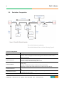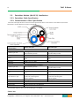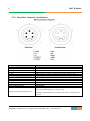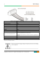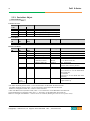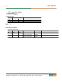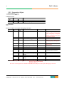
1
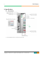
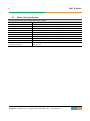
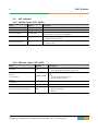
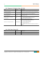
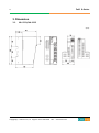
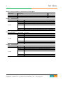
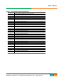
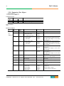
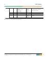
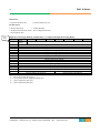
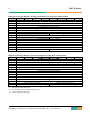
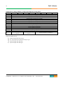
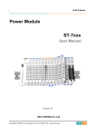
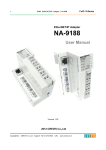
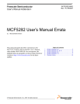
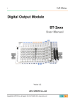
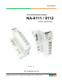
1 FnIO S-Series DeviceNet Network Adapter NA-9111 / 9112 User Manual Version 1.10 2013 CREVIS Co.,LTD Copyright(C) CREVIS Co.,Ltd Support +82-31-899-4599 URL : www.crevis.co.kr 2 FnIO S-Series DOCUMENT CHANGE SUMMARY REV 1.0 PAGE New Document 1.01 1.02 1.03 1.04 36 11 All 6 1.05 All 1.06 25 REMARKS DATE EDITOR Draft 2011/05/27 MH Lee Default status byte is 0 byte both NA-9111 and 9112 IO LED status All page Revision (Rename to Table) Add your experience Modify the wrong letters, 2011/06/22 2011/10/21 2011/10/31 2012/1/13 MH Lee JE Kang JE Kang JE Kang 2012/2/10 JE Kang 2012/3/08 2012/3/22 JE Kang JE Kang 2013/4/4 2013/7/3 JE Kang JE Kang Changed Object, Changed Cover Add ‘Description of Status byte’ Add certificate RoHS 1.07 1.08 1.09 Changed Crevis TEL Environment Spec. 50℃→55℃ (UL Temp) Changed Power Dissipation 2013/7/17 JE Kang 1.10 Modify the Pin Description 2014/05/08 YMKIM Copyright(C) CREVIS Co.,Ltd Support +82-31-899-4599 URL : www.crevis.co.kr 3 FnIO S-Series CONTENTS 1. Important Notes ......................................................................................................................................................... 6 1.1. Safety Instruction ...................................................................................................................................... 7 1.1.1. Symbols ......................................................................................................................................................... 7 1.1.2. Safety Notes ................................................................................................................................................ 7 1.1.3. Certification ................................................................................................................................................. 7 2. Specification ..................................................................................................................................................................... 8 3. 2.1. The Interface ............................................................................................................................................... 8 2.2. General Specification............................................................................................................................... 9 2.3. Device Net Specification...................................................................................................................... 10 2.4. LED Indicator............................................................................................................................................. 11 2.4.1. Module Status LED (MOD) ................................................................................................................. 11 2.4.2. Network Status LED (NET) .................................................................................................................. 11 2.4.3. Expansion I/O Module Status LED (I/O) ....................................................................................... 12 2.4.4. Field Power Status LED ........................................................................................................................ 12 Dimension.................................................................................................................................................................... 13 3.1. 4. 5. NA-9111/NA-9112.................................................................................................................................. 13 Mechanical Set Up................................................................................................................................................... 14 4.1. Total Expansion........................................................................................................................................ 14 4.1. Plugging and Removal of the Components. .............................................................................. 14 Configuration and Operation ............................................................................................................................. 15 5.1. 5.1.1. FnBus Specification ................................................................................................................................ 15 FnBus System ............................................................................................................................................ 15 Copyright(C) CREVIS Co.,Ltd Support +82-31-899-4599 URL : www.crevis.co.kr 4 FnIO S-Series 5.1.1. FnBus Pin Description ........................................................................................................................... 17 5.2. DeviceNet Composition ....................................................................................................................... 18 5.3. DeviceNet Module (NA-9112) Installations ................................................................................ 19 5.3.1. DeviceNet Cable Specification .......................................................................................................... 19 5.3.2. Communication Cable Specification .............................................................................................. 19 5.3.3. DeviceNet Connector Specification ................................................................................................ 21 5.3.4. Terminator Resistor Specification .................................................................................................... 23 5.4. DeviceNet Module (NA-9112/9111) Configurations ............................................................... 24 5.4.1. DeviceNet MAC ID Setup .................................................................................................................... 24 5.4.2. I/O Process Image Map ....................................................................................................................... 25 5.4.3. Object Models .......................................................................................................................................... 25 5.5. Object Setting .......................................................................................................................................... 27 5.5.1. Identity Object ......................................................................................................................................... 27 5.5.2. Message Router Object ....................................................................................................................... 28 5.5.3. DeviceNet Object .................................................................................................................................... 29 5.5.4. Assembly Object...................................................................................................................................... 30 5.5.5. Connection Object ................................................................................................................................. 31 5.5.6. Acknowledge Handler Object ........................................................................................................... 34 5.5.7. FnBus Manager Object ......................................................................................................................... 35 5.5.8. Expansion Slot Object ........................................................................................................................... 38 5.5.9. I/O Format Setting ................................................................................................................................. 42 5.5.10. EDS Setting ................................................................................................................................................ 46 5.6. Example ....................................................................................................................................................... 51 Copyright(C) CREVIS Co.,Ltd Support +82-31-899-4599 URL : www.crevis.co.kr 5 FnIO S-Series 5.6.1. Example of Input Process Image Map ....................................................................................... 51 5.6.2. Example of Output Process Image Map ...................................................................................... 54 5.7. 6. Check List ................................................................................................................................................... 56 Trouble Shooting...................................................................................................................................................... 57 Appendix ............................................................................................................................................................................... 59 A.1. Product List............................................................................................................................................................. 59 A.2. Glossary .................................................................................................................................................................... 60 Copyright(C) CREVIS Co.,Ltd Support +82-31-899-4599 URL : www.crevis.co.kr 6 FnIO S-Series 1. Important Notes Solid state equipment has operational characteristics differing from those of electromechanical equipment. Safety Guidelines for the Application, Installation and Maintenance of Solid State Controls describes some important differences between solid state equipment and hard-wired electromechanical devices. Because of this difference, and also because of the wide variety of uses for solid state equipment, all persons responsible for applying this equipment must satisfy themselves that each intended application of this equipment is acceptable. In no event will CREVIS be responsible or liable for indirect or consequential damages resulting from the use or application of this equipment. The examples and diagrams in this manual are included solely for illustrative purposes. Because of the many variables and requirements associated with any particular installation, CREVIS cannot assume responsibility or liability for actual use based on the examples and diagrams. Warning! If you don’t follow the directions, it could cause a personal injury, damage to the equipment or explosion Do not assemble the products and wire with power applied to the system. Else it may cause an electric arc, which can result into unexpected and potentially dangerous action by field devices. Arching is explosion risk in hazardous locations. Be sure that the area is non-hazardous or remove system power appropriately before assembling or wiring the modules. Do not touch any terminal blocks or IO modules when system is running. Else it may cause the unit to an electric shock or malfunction. Keep away from the strange metallic materials not related to the unit and wiring works should be controlled by the electric expert engineer. Else it may cause the unit to a fire, electric shock or malfunction. Caution! If you disobey the instructions, there may be possibility of personal injury, damage to equipment or explosion. Please follow below Instructions. • Check the rated voltage and terminal array before wiring. Avoid the circumstances over 55℃ of temperature. Avoid placing it directly in the sunlight. • Avoid the place under circumstances over 85% of humidity. • Do not place Modules near by the inflammable material. Else it may cause a fire. • Do not permit any vibration approaching it directly. • Go through module specification carefully, ensure inputs, output connections are made with the specifications. Use standard cables for wiring. • Use Product under pollution degree 2 environment. Copyright(C) CREVIS Co.,Ltd Support +82-31-899-4599 URL : www.crevis.co.kr 7 FnIO S-Series 1.1. Safety Instruction 1.1.1. Symbols Identifies information about practices or circumstances that can cause an explosion in a hazardous environment, which may lead to personal injury or death property damage or economic loss Identifies information that is critical for successful application and understanding of the product Identifies information about practices or circumstances that can lead to personal injury, property damage, or economic loss. Attentions help you to identity a hazard, avoid a hazard, and recognize the consequences 1.1.2. Safety Notes The modules are equipped with electronic components that may be destroyed by electrostatic discharge. When handling the modules, ensure that the environment (persons, workplace and packing) is well grounded. Avoid touching conductive components, e.g. FnBUS Pin. 1.1.3. Certification c-UL-us UL Listed Industrial Control Equipment, certified for U.S. and Canada See UL File E235505 CE Certificate EN 61000-6-2; Industrial Immunity EN 61000-6-4; Industrial Emissions FCC RoHS (EU, CHINA) Copyright(C) CREVIS Co.,Ltd Support +82-31-899-4599 URL : www.crevis.co.kr 8 FnIO S-Series 2. Specification 2.1. The Interface The wiring diagram of NA-9111 and NA-9112 are the same. Copyright(C) CREVIS Co.,Ltd Support +82-31-899-4599 URL : www.crevis.co.kr 9 FnIO S-Series 2.2. General Specification General Specification Supply voltage : 24Vdc nominal Supply voltage range : 11~28.8Vdc System Power Protection : Output current limit(Min. 1.5A) Reverse polarity protection Power Dissipation 40mA typical @24Vdc Current for I/O Module 1.2A @5Vdc Isolation DeviceNet to internal logic : Non-isolation Internal logic to I/O driver : Isolation Field Power Max. Current Field Power Supply voltage : 24Vdc nominal Supply voltage range : 11~28.8Vdc DC 10A Max. Contact Weight 155g Module Size 42mm x 99mm x 70mm Environment Condition Environmental Specifications Operating Temperature -20℃~55℃ Storage Temperature -40℃~85℃ Relative Humidity 5% ~ 90% non-condensing Operating Altitude 2000m Mounting DIN rail General Specifications Shock Operating 10g Shock Non-Operating 30g Vibration/shock resistance EMC resistance burst/ESD Installation Pos. / Protect. Class Product Certifications Copyright(C) CREVIS Co.,Ltd Displacement : 0.012Inch p-p from 10~57Hz Acceleration : 2G’s from 57~500Hz Sweep Rate : 1 octave Per Minute Axes to test : x, y, z Frequency Sweeps Per Axis : 10 EMC Directive Variable/IP20 UL/cUL, CE, FCC, DeviceNet(ODVA) Support +82-31-899-4599 URL : www.crevis.co.kr 10 FnIO S-Series 2.3. Device Net Specification Interface Specification, NA-9111/9112 (DeviceNet Adapter) Adapter Type Max. Expansion Module Max. Input Size Max. Output Size Max. Length Bus Line Max. Nodes Communication Speed Network Protocol Interface Connector Node MAC ID Setup Module Location Field Power Detection Copyright(C) CREVIS Co.,Ltd Group 2 Only Slave 32 slots NA-9111 : 32 bytes , NA-9112 : 252 bytes NA-9111 : 32 bytes , NA-9112 : 252 bytes Max.100m@500Kbps, Max. 250m@250Kbps, Max. 500m@125Kbps 64 nodes 125Kbps, 250Kbps, 500Kbps, auto baud supported Poll, Bit-Strobe, Cyclic, COS 5pin Open male connector 2 Rotary Switches Starter module – left side of FnIO system About 11Vdc Support +82-31-899-4599 URL : www.crevis.co.kr 11 FnIO S-Series 2.4. LED Indicator 2.4.1. Module Status LED (MOD) State LED is: To indicate: No Power Device Operational Off Green Device in Standby Flashing Green Minor Fault Flashing Red Unrecoverable Fault Red No power is supplied to the unit. The unit is operating in normal condition. The EEPROM parameter is not initialized yet. Serial Number is zero value (0x00000000) The unit has occurred recoverable fault in self-testing. - EEPROM checksum fault The unit has occurred unrecoverable fault in self-testing. - Firmware fault 2.4.2. Network Status LED (NET) State LED is: No Power Off On-line, Not connected Flashing Green On-line, Connected Connection Time-out Critical Communication Failure Copyright(C) CREVIS Co.,Ltd To indicate: Device is not on-line or may not be powered - Not completed the Dup-MAC_ID test yet Device is on-line but has no connections in the established state. - Passed the Dup-MAC_ID test - Not allocated to a master Green Device is on-line and allocated to a master Flashing Red One or more I/O connections are in the time-out state. Failed communication - Duplicate MAC ID - Bus-off Red Support +82-31-899-4599 URL : www.crevis.co.kr 12 FnIO S-Series 2.4.3. Expansion I/O Module Status LED (I/O) State Not Powered No Expansion Module FnBus On-line, Do not Exchanging I/O FnBus Connection, Run Exchanging IO LED is: To indicate: Off Device has no expansion module or may not be powered Flashing Green FnBus is normal but does not exchanging I/O data (Passed the expansion module configuration). Green Exchanging I/O data FnBus connection fault during exchanging IO Red Expansion Configuration Failed Flashing Red One or more expansion module occurred in fault state. - Changed expansion module configuration. - FnBus communication failure. Failed to initialize expansion module - Detected invalid expansion module ID. - Overflowed Input/output Size - Too many expansion module - Initial protocol failure - Mismatch vendor code between adapter and expansion module. 2.4.4. Field Power Status LED State LED is : To indicate : Not Supplied Field Power Off Not supplied 24V dc field power Supplied Field Power Green Supplied 24V dc field power Copyright(C) CREVIS Co.,Ltd Support +82-31-899-4599 URL : www.crevis.co.kr 13 FnIO S-Series 3. Dimension 3.1. NA-9111/NA-9112 (mm) Copyright(C) CREVIS Co.,Ltd Support +82-31-899-4599 URL : www.crevis.co.kr 14 FnIO S-Series 4. Mechanical Set Up 4.1. Total Expansion The number of the module assembly that can be connected is 32. So the maximum length is 426mm Exception ST-2748 is excepted to calculate maximum length because that is double width module. 4.2. Plugging and Removal of the Components. As above figure in order to safeguard the FnIO module from jamming, it should be fixed onto the DIN rail with locking level. To do so, fold on the upper of the locking lever. To pull out the FnIO module, unfold the locking lever as below figure. Before work is done on the components, the voltage supply must be turned off. Copyright(C) CREVIS Co.,Ltd Support +82-31-899-4599 URL : www.crevis.co.kr 15 FnIO S-Series 5. Configuration and Operation 5.1. FnBus Specification 5.1.1. FnBus System Copyright(C) CREVIS Co.,Ltd Support +82-31-899-4599 URL : www.crevis.co.kr 16 FnIO S-Series • Network Adapter Module The Network Adapter Module forms the link between the field bus and the field devices with the Expansion Modules. The connection to different field bus systems can be established by each of the corresponding Network Adapter Module, e.g. for SyncNet, PROFIBUS, CANopen, DeviceNet, Ethernet/IP, CC-Link, MODBUS/Serial, MODBUS/TCP etc. • Expansion Module The Expansion Modules are supported a variety of input and output field devices. There are digital and analog input/output modules and special function modules. • Two types of FnBus Message - Service Messaging - I/O Messaging Copyright(C) CREVIS Co.,Ltd Support +82-31-899-4599 URL : www.crevis.co.kr 17 FnIO S-Series 5.1.2. FnBus Pin Description Communication between the NA series and the expansion module as well as system / field power supply of the bus modules is carried out via the internal bus. It is comprised of 6 data pin and 2 field power pin. No. 1 2 3 4 5 6 7 8 Name Vcc GND Token Output Serial Output Serial Input Reserved Field GND Field Vcc Description System supply voltage (5V dc). System Ground. Token output port of Processor module. Transmitter output port of Processor module. Receiver input port of Processor module. Reserved for bypass Token. Field Ground. Field supply voltage (24Vdc). Do not touch data and field power pins in order to avoid soiling and damage by ESD noise. Copyright(C) CREVIS Co.,Ltd Support +82-31-899-4599 URL : www.crevis.co.kr 18 FnIO S-Series 5.2. DeviceNet Composition DeviceNet Network Installation DeviceNet Network Set up is like following figure2. Network Composition Name Node Trunk / Drop Line Connection Mode Terminator Resistor Communication Power Copyright(C) CREVIS Co.,Ltd Description Node is Slave that is charged each address number. DeviceNet is comprised of Master and Slave. Master manages DeviceNet and organizes external I/O in Slave. Slave contacts external I/O. Trunk line is cable that is installed terminator resistor. Drop line is cable that branch from trunk line In the DeviceNet, both trunk and drop line is used. Number of Connection mode for DeviceNet is 2 modes. First is T-branch and Second is multi-drop. T-branch is method that branches off drop-line by T-branch tap Multi drop is method what trunk and drop line contacts with node directly. Terminator resistor is that is installed for reduction a reflected wave in both ends trunk line. For using DeviceNet, user must supply communication power to each node connector through the DeviceNet cable. Support +82-31-899-4599 URL : www.crevis.co.kr 19 FnIO S-Series 5.3. DeviceNet Module (NA-9112) Installations 5.3.1. DeviceNet Cable Specification 5.3.2. Communication Cable Specification DeviceNet Cable Specification. In the DeviceNet Specification There is the exclusive cable bellows (DeviceNet Specification Volume Release2.0 Errate2, appendix B) Physical Characteristics Communication cable Conductor pair size Insulation diameter Colors Pair twist/ft Impedance Power pair Conductor pair size Insulation diameter Color Tape shield over pair Drain wire Roundness Agency certification Jacket marker Thick Cable Spec Thin Cable Spec #18 Copper(minimum) : 19 strand min(individually tinned) 0.150 inches Light blue White 3(approx.) 120Ω ± 10% (at 1MHz) #24 Copper(minimum) : 19 strand min(individually tinned) 0.077 inches Light blue White 5(approx.) #15 Copper(minimum) : 19 strand min(individually tinned) #22 Copper(minimum) : 19 strand min(individually tinned) 0.098 inches Red Black 1.0mil/1mil,Al/Mylar Al side out w/shorting fold (pull-on applied) #18 Copper(minimum) : 19 strand min Radius delta to be within 15% of 0.5 0.D NEC(UL) type CL2(min.) Vender name & part#, and additional 0.055 inches Red Black 1.0mil/1mil,Al/Mylar Al side out w/shorting fold (pull-on applied) #22 Copper(minimum) : 19 strand min The maximum length of network for each cable type is as follows. -Thick Cable Copyright(C) CREVIS Co.,Ltd Support +82-31-899-4599 URL : www.crevis.co.kr 20 Communication rate 125Kb 250Kb 500Kb FnIO S-Series Truck Length 500m(1640ft) 250m(820ft) 100m(328ft) Truck Exchange (Thick Cable) 1.0 1.0 1.0 Cumulative drop Maximum drop 156m(512ft) 76m(256ft) 38m(128ft) 6m(20ft) 6m(20ft) 6m(20ft) Cumulative drop Maximum drop 156m(512ft) 76m(256ft) 38m(128ft) 6m(20ft) 6m(20ft) 6m(20ft) -Thin Cable Communication rate 125Kb 250Kb 500Kb Truck Length 100m(328ft) 100m(328ft) 100m(328ft) Copyright(C) CREVIS Co.,Ltd Truck Exchange (Thick Cable) 5.0 2.5 1.0 Support +82-31-899-4599 URL : www.crevis.co.kr 21 FnIO S-Series 5.3.3. DeviceNet Connector Specification Male General Characteristics Number of Pins Coupling Nut Coupling Nut Thread Rotation Pin out Female General Characteristics Number of Pins Coupling Nut Coupling Nut Thread Rotation Pin out Physical Characteristics Specification 5 Male 7/8–166 UN-2A THD Optional Drain : Pin1, V+ : Pin2, V- : Pin3, CAN_H : Pin4, CAN_L : Pin5 Specification 5 Female 7/8–166 UN-2B THD Required Drain : Pin1, V+ : Pin2, V- : Pin3, CAN_H : Pin4, CAN_L : Pin5 Specification 30 micro inch gold minimum over 50 micro inch nickel minimum or 5 micro inch gold minimum over 20 micro inch Wiping Contact Plating Requirements Palladium-nickel minimum over 50 micro inch nickels. All gold must be 24 karat Copyright(C) CREVIS Co.,Ltd Support +82-31-899-4599 URL : www.crevis.co.kr 22 FnIO S-Series Male General Characteristics Number of Pins Coupling Nut Coupling Nut Thread Rotation Pin out Female General Characteristics Number of Pins Coupling Nut Coupling Nut Thread Rotation Pin out Physical Characteristics Specification 5 None None None V- : Pin1, CAN_L : Pin2, Shield : Pin3, CAN_H : Pin4, V+ : Pin5 Specification 5 None None None V- : Pin1, CAN_L : Pin2, Shield : Pin3, CAN_H : Pin4, V+ : Pin5 Specification 30 micro inch gold minimum over 50 micro inch nickel minimum or 5 micro inch gold minimum over 20 micro inch Wiping Contact Plating Requirements Palladium-nickel minimum over 50 micro inch nickels. All gold must be 24 karat Wiping Contract Life 1000 insertion - extractions Electrical Characteristics Specification Operating Voltage 25 Volt minimum Contact Rating 8 Amps minimum Device network power is 24V. Network and I/O field power must be separated One power is provided per network The use of an incorrect supply voltage or frequency can cause severe damage to the component. Copyright(C) CREVIS Co.,Ltd Support +82-31-899-4599 URL : www.crevis.co.kr 23 FnIO S-Series 5.3.4. Terminator Resistor Specification Terminator Resistor Specification of terminator Resistors are Carbon film Resistor what Resistance Specification is 120Ω, 1%, 1/4W Copyright(C) CREVIS Co.,Ltd Support +82-31-899-4599 URL : www.crevis.co.kr 24 FnIO S-Series 5.4. DeviceNet Module (NA-9112/9111) Configurations 5.4.1. DeviceNet MAC ID Setup Each DeviceNet Adapter must have a unique MAC ID (from 0 to 63) so that it can be addressed independently from other nodes. If value range of 2 rotary switches is 64~99, the MAC ID can be set by from network (software). X 10 (MSD) X 1 (LSD) The above figure shows MAC ID 27(=2*10 + 7*1) of a slave MAC ID addresses have to be unique throughout the entire interconnected Networks. Copyright(C) CREVIS Co.,Ltd Support +82-31-899-4599 URL : www.crevis.co.kr 25 FnIO S-Series 5.4.2. I/O Process Image Map An expansion module may have 3 types of data as I/O data, configuration parameter and memory register. The data exchange between network adapter and expansion modules is done via an I/O process image data by FnBus protocol. The following figure shows the data flow of process image between network adapter and expansion modules. Status byte is set by default as not. How to set the Status byte is refer to 5.5.7. Description of Status byte Bit Description Explanation Decimal Bit 00-03 Reserved Field Power Status 04-06 07 Explanation 0: Exchange IO data(normal operation) 1: Stop Exchanging IO(ready to exchange IO) 2: Fn-Bus Communication Fault 3: Slot Configuration Fault 4: No Expansion Slot Reserved 0: 24Vdc Field Power On 1: 24Vdc Field Power Off 5.4.3. Object Models A DeviceNet node is modeled as a collection of Objects. An Object provides an abstract representation of a particular component within a product. The realization of this abstract object model within a product is implementation dependent. In other words, a product internally maps this object model in a fashion specific to its implementation. The objects and their components are addressed by a uniform addressing scheme consisting of: Media Access Control Identifier (MAC ID), an integer identification value assigned to each node on a DeviceNet network. Class Identifier (Class ID), an integer identification value assigned to each Object Class accessible from the network. Instance Identifier (Instance ID), an integer identification value assigned to an Object Instance that identifies it among all Instances of the same Class. Copyright(C) CREVIS Co.,Ltd Support +82-31-899-4599 URL : www.crevis.co.kr 26 FnIO S-Series Attribute Identifier (Attribute ID), an integer identification value assigned to a Class and/or Instance Attribute. Service Code, an integer identification value which denotes a particular Object Instance and/or Object Class function. Supported Objects - Device Type Number: 0CHEX (Communications Adapter) Name of Object Identity Message Router DeviceNet Assembly Connection Acknowledge Handler FnBus Manager Expansion Slot Type Required Required Required Required Required Required Vendor-specific Vendor-specific Number of Instances 1 1 1 2 4 1 1 1~32 Class Code 01HEX 02 HEX 03 HEX 04 HEX 05 HEX 2B HEX 70 HEX 71 HEX Objects Behavior, Interface Object Identity DeviceNet Assembly Connection Acknowledge Handler FnBus Manager Expansion Slot Behavior Device identification, reset service Configures port attributes Defines I/O data format and concatenates configuration data Contains the number of logical ports into or out-of the device Manage the reception of message acknowledgments Management functions for the Fn-Bus Management functions for the expansion slot Copyright(C) CREVIS Co.,Ltd Support +82-31-899-4599 Interface Message Router Message Router I/O Connection or Message Router Message Router Message Router Message Router Message Router URL : www.crevis.co.kr 27 FnIO S-Series 5.5. Object Setting 5.5.1. Identity Object Class Code: 01HEX Common Services Service Implemented for Code Class Instance 0x05 No Yes 0x0E No Service Name Value Reset 0: Reset Only 1: Reset and Factory Default Yes Get_Attribute_Single Access Rule Get Get Get Get Name Data Type Value Vendor ID Device Type Product Code Revision - Major - Minor Status Serial Number Product Name - String Length - ASCII String CRC Device Fault Code UINT UINT UINT Structure of: USINT USINT WORD UDINT Structure of: USINT STRING UINT USINT 741 (Crevis Co., Ltd) 0CHEX (Communications Adapter) 256(NA-9111), 257(NA-9112) USINT UINT 111: NA-9111, 112 : NA-9112 0x0A17 “A-17” UDINT UDINT 0xYYYYMMDD ex) 0x20030417 2003/04/17 0xYYYYMMDD Class Attributes None Instance Attributes Instance Attribute ID ID 1 1 2 3 4 5 6 7 Get Get Get 9 100(64h) Get Get Vendor-specific 102(66h) Get 103(67h) Get 104(68h) Get Firmware Code ODVA Conformance Test Revision Firmware Release Date 107(6Bh) Get Inspection Date Copyright(C) CREVIS Co.,Ltd Support +82-31-899-4599 1~9 1 ~ 255 Defined in Spec Unique Number 24 “NA9112_DeviceNet_Adapter” or “NA9111_DeviceNet_Adapter” EEPROM Checksum Code *0x11B8 00 HEX : Normal Operation Bit 0: No expansion slot Bit 1: Too many expansion slot Bit 2: Overflow I/O size Bit 3: I/O Configuration failure Bit 4: EEPROM Checksum fault Bit 6: Invalid Module ID Bit 7: Firmware fault URL : www.crevis.co.kr 28 FnIO S-Series 5.5.2. Message Router Object Class Code: 02HEX Common Services None Class Attributes None Instance Attributes None Copyright(C) CREVIS Co.,Ltd Support +82-31-899-4599 URL : www.crevis.co.kr 29 FnIO S-Series 5.5.3. DeviceNet Object Class Code: 03HEX Common Services Service Implemented for Code Class Instance 0x0E Yes Yes 0x10 No Yes 0x4B No Yes 0x4C No Yes Service Name Get_Attribute_Single Set_Attribute_Single Allocate_Master/Slave_Connection_Set Release_Master/Slave_Connection_Set Class Attributes Instance Attribute ID ID 0 1 Access Rule Get Name Data Type Value Revision UINT 02, 00 Instance Attributes Instance Attribute ID ID 1 1 2 3 4 5 Access Rule Get/Set* Get/Set** Get/Set Get Get Name Data Type Value MAC ID Baud Rate Bus off Interrupt Bus-Off Counter Allocation Information - Allocation Choice - Master's MAC ID MACID Switch Value USINT USINT BOOL USINT Structure of: BYTE USINT USINT 0 ~ 63 0=125K, 1=250K, 2=500K faulted node recovery 0 ~ 255 Auto-Baud Action BOOL Quick Start, TBD BOOL 0: Enabled (default) (Not allowed to set the Baud Rate from Network) 1: Disabled (Allowed to set the Baud Rate from Network) 0:Noarmal Start-up 1:Quick Start-up 8 Get Vendor-specific 100(64h) Get/Set 101(65h) (Only NA-9112) Get/Set 0~63: Master MAC ID, 255: unallocated 0 ~ 99 Actual value of Rotary Switch *The MAC ID Rotary Switch value = 0~63: Not allowed to set the MAC ID from Network. The MAC ID Rotary Switch value = 64~99: Allowed to set the MAC ID from Network. Behavior: Changed new MAC ID → Device will be restarted. **The Auto-Baud Action (attribute #100) value = 0: Not allowed to set the Baud Rate form Network The Auto-Baud Action (attribute #100) value = 1: Allowed to set the Baud Rate form Network Behavior: Changed new Baudrate → Device won’t be restarted. (Waiting for reset service or power reset) Copyright(C) CREVIS Co.,Ltd Support +82-31-899-4599 URL : www.crevis.co.kr 30 FnIO S-Series 5.5.4. Assembly Object Class Code: 04HEX Common Services Service Implemented for Code Class Instance 0x0E No Yes 0x10 No Yes Service Name Get_Attribute_Single Set_Attribute_Single Class Attributes None Input Instance Attributes Input/output Instance ID Instance Attribute Access ID ID Rule 100(64h) 3 Get 150(96h) 3 Set/Get Copyright(C) CREVIS Co.,Ltd Name Data Type Value Input (Produced) Process Image Data Output (Consumed) Process Image Data Array n BYTE Array n BYTE Input process current image data Support +82-31-899-4599 Output process current image data URL : www.crevis.co.kr 31 FnIO S-Series 5.5.5. Connection Object Class Code: 05HEX Common Services Service Implemented for Code Class Instance 0x0E No Yes 0x10 No No Service Name Get_Attribute_Single Set_Attribute_Single Class Attributes None Instance Attributes for Explicit Messaging Connection Instance Attribute Access Name ID ID Rule 1 1 Get state Data Type Value USINT Defined in Spec * 0x03 : The connection has been validly/fully configured and the configuration has been successfully applied. 0: Explicit Message 83HEX *0x040B : MAC ID=01, Message group 2, Message ID 3 *0x040C : MAC ID=01, Message ID 4 21HEX NA-9111: 38, NA-9112 : 259 NA-9111: 38, NA-9112 : 259 2504 (default) Timer Resolution of 8msec 3 : Deferred Delete (default) 00, 00 2 3 4 Get Get Get instance_type transportClass_trigger produced_connection_id USINT BYTE UINT 5 Get consumed_connection_id UINT 6 7 8 9 Get Get Get Get/Set initial_comm_characteristics produced_connection_size consumed_connection_size expacted_packet_rate BYTE UINT UINT UINT 12 13 Get/Set Get watchdog_timeout_action USINT produced_connection_path_ UINT length 14 Get produced_connection_path Array of USINT Empty 15 Get consumed_connection_path_ UINT 00, 00 length 16 Get consumed_connection_path Array of USINT Empty attribute 3 transport Class trigger = 0x83 → Direction=Server, Production Trigger=IGNORED, Transport Class = 3. This is the value assigned to this attribute within the server end-point of an Explicit Messaging Connection Copyright(C) CREVIS Co.,Ltd Support +82-31-899-4599 URL : www.crevis.co.kr 32 FnIO S-Series Instance Attributes for Poll I/O Connection Instance Attribute Access Name ID ID Rule 2 1 Get State 2 Get instance_type 3 Get transportClass_trigger 4 Get produced_connection_id Data Type Value USINT USINT BYTE UINT 5 Get consumed_connection_id UINT 6 7 8 9 Get Get Get Get/Set initial_comm_characteristics produced_connection_size consumed_connection_size expacted_packet_rate BYTE UINT UINT UINT 12 13 Get Get USINT UINT 14 15 Get Get Array of USINT UINT 0 or 6 16 Get watchdog_timeout_action produced_connection_path_ length produced_connection_path consumed_connection_path_ length consumed_connection_path Defined in Spec 1: I/O Message 82HEX * 0x03C1 : MAC ID=01, Message ID=6, Unconnected Explicit Request Message * 0x040D : MAC ID=01, Message ID=5, Group 2 message Identifier 01HEX 9111 : 0 to 33, 9112 : 0 to 252 9111 : 0 to 32, 9112 : 0 to 252 Timer Resolution of 8msec * 200(decimal) 0: Time Out (default) 0 or 6 Instance Attributes for Bit-Strobe I/O Connection Instance Attribute Access Name ID ID Rule 3 1 Get state 2 Get instance_type 3 Get transportClass_trigger 4 Get produced_connection_id Array of USINT Data Type Value USINT USINT BYTE UINT 5 Get consumed_connection_id UINT 6 7 8 9 Get Get Get Get/Set initial_comm_characteristics produced_connection_size consumed_connection_size expacted_packet_rate BYTE UINT UINT UINT 12 13 Get Get USINT UINT 14 15 Get Get Array of USINT UINT 0 or 6 16 Get watchdog_timeout_action produced_connection_path_ length produced_connection_path consumed_connection_path_ length consumed_connection_path Defined in Spec 1: I/O Message 82HEX *0x0381 : MAC ID=01, Message ID=14, Message group 1 *0X0400 : MAC ID = 00, Message ID = 0, Message group 2 02HEX 0 to 8 8 Timer Resolution of 8msec * 200 0: Time Out (default) 0 or 6 Copyright(C) CREVIS Co.,Ltd Support +82-31-899-4599 Array of USINT URL : www.crevis.co.kr 33 FnIO S-Series Instance Attributes for COS I/O Connection (Acknowledged) Instance Attribute Access Name ID ID Rule 4 1 Get State 2 Get instance_type 3 Get transportClass_trigger 4 Get produced_connection_id 5 Get consumed_connection_id 6 Get initial_comm_characteristics 7 Get produced_connection_size 8 Get consumed_connection_size 9 Get/Set expacted_packet_rate 12 Get/Set watchdog_timeout_action 13 Get produced_connection_path_ length 14 Get produced_connection_path 15 Get consumed_connection_path_ length 16 Get consumed_connection_path 17 Get/Set production_inhibit_time Instance Attributes for COS I/O Connection (Unacknowledged) Instance Attribute Access Name ID ID Rule 4 1 Get State Data Type Value USINT USINT BYTE UINT UINT BYTE UINT UINT UINT USINT UINT Defined in Spec 1: I/O Message 12HEX 1 9111 : 0 to 33, 9112 : 0 to 252 0 Timer Resolution of 8msec 0: Time Out (default) 0 or 6 Array of USINT UINT 4 Array of USINT UINT 20 2B 24 01 00, 00 Data Type Value USINT 2 3 4 Get Get Get instance_type transportClass_trigger produced_connection_id USINT BYTE UINT 5 6 7 8 9 Get Get Get Get Get/Set consumed_connection_id initial_comm_characteristics produced_connection_size consumed_connection_size expacted_packet_rate UINT BYTE UINT UINT UINT 12 13 Get/Set Get USINT UINT 14 15 Get Get Array of USINT UINT 0 16 17 Get Get/Set watchdog_timeout_action produced_connection_path_ length produced_connection_path consumed_connection_path_ length consumed_connection_path production_inhibit_time Defined in Spec * 0x01 : Configuring 1: I/O Message 10HEX * 0x0341 MAC ID : 01, Message ID=13, Message Group 1 0FFFFHEX 0FHEX 9111 : 0 to 33, 9112 : 0 to 252 0 Timer Resolution of 8msec * 0x00 0: Time Out (default) 0 or 6 Array of USINT UINT Empty 00, 00 Copyright(C) CREVIS Co.,Ltd Support +82-31-899-4599 URL : www.crevis.co.kr 34 FnIO S-Series 5.5.6. Acknowledge Handler Object Class Code: 2BHEX Common Services Service Implemented for Code Class Instance 0x0E Yes Yes Service Name Get_Attribute_Single Class Attributes None Instance Attributes Instance Attribute ID ID 1 1 2 3 Access Rule Set Get Get Copyright(C) CREVIS Co.,Ltd Name Data Type Value Acknowledge Timer Retry Limit COS Producing Connection Instance UNIT USINT UINT Default: 16 1 4 Support +82-31-899-4599 URL : www.crevis.co.kr 35 FnIO S-Series 5.5.7. FnBus Manager Object Class Code: 70HEX Common Services Service Implemented for Code Class Instance 0x0E No Yes 0x10 No Yes Service Name Get_Attribute_Single Set_Attribute_Single Class Attributes None Instance Attributes Instance Attribute ID ID 1 1 2 3 4 Access Rule Get Get Get Get Name Data Type Value Number of Slot Num of Activated Slot Num of Deactivated Slot External IDs (include deactivated slot) 5 Get/Set* Selection of Produced Connection Type USINT USINT USINT Array of 33 BYTE USINT 6 Get/Set* Selection of Consumed Connection Type USINT 7 8 9 10 Get/Set* Get Get Get Slot Active Flag Slot Live List Slot Alarm List Fn-Bus Status DWORD DWORD DWORD USINT 11 Get UINT 12 Get Input (Produced) Byte Size Output (Consumed) Byte Size See Table 5.6. See Appendix A.1. See Table 5.1. Valid value range is 0,1,2,3 (default 2) See Table 5.2. Valid value range is 0,1 (default 0) See Table 5.3 See Table 5.4. See Table 5.5. 0: Normal Operation 1: Fn-Bus Standby 2: Fn-Bus Connection Fault 3: Expansion Configuration Fault 4: No Expansion Module IO input byte size(only NA-9112) UINT IO output byte size(only NA-9112) *After the system is reset, the new “Set Value” action is applied. If changed slot location, set default value automatically. Table 5.1. Selection of Input (Produced) Process Image Mode Selection Input Description Image Mode 0 Status(1byte) + Uncompressed Input Processing Data 1 Status(1byte) + Compressed Input Processing Data 2 Uncompressed Input Processing Data 3 Compressed Input Processing Data Copyright(C) CREVIS Co.,Ltd Support +82-31-899-4599 URL : www.crevis.co.kr Default 36 FnIO S-Series Table 5.2. Selection of Output (Consumed) Process Image Mode Selection Output Description Image Mode 0 Uncompressed Output Processing Data 1 Compressed Output Processing Data default Table 5.3. Slot Active Flag DWORD(32bits) Decimal Bit Bit 00 Bit 01 Bit 02 . Get/Set . . Bit 30 Bit 31 Description Activate/Deactivate flag for slot position #1 (0:Active, 1:Decative) Activate/Deactivate flag for slot position #2 (0:Active, 1:Decative) Activate/Deactivate flag for slot position #3 (0:Active, 1:Decative) . . . Activate/Deactivate flag for slot position #31 (0:Active, 1:Decative) Activate/Deactivate flag for slot position #32 (0:Active, 1:Decative) Table 5.4. Slot Live List DWORD(32bits) Decimal Bit Bit 00 Bit 01 Bit 02 . Get/Set . . Bit 30 Bit 31 Description This bit is set (1) when slot position #1 is available to exchange IO This bit is set (1) when slot position #2 is available to exchange IO This bit is set (1) when slot position #3 is available to exchange IO . . . This bit is set (1) when slot position #31 is available to exchange IO This bit is set (1) when slot position #32 is available to exchange IO Table 5.5. Slot Alarm List DWORD(32bits) Decimal Bit Bit 00 Bit 01 Bit 02 . Get/Set . . Bit 30 Bit 31 Description This bit is set (1) when an error is detected in slot position #1 This bit is set (1) when an error is detected in slot position #2 This bit is set (1) when an error is detected in slot position #3 . . . This bit is set (1) when an error is detected in slot position #31 This bit is set (1) when an error is detected in slot position #32 Copyright(C) CREVIS Co.,Ltd Support +82-31-899-4599 URL : www.crevis.co.kr 37 FnIO S-Series Table 5.6. Byte External IDs (=Expansion Module ID) Description 0 Network Adapter Module External ID = 0x00 1 External ID for slot position #1 2 External ID for slot position #2 3 External ID for slot position #3 4 External ID for slot position #4 5 External ID for slot position #5 6 External ID for slot position #6 7 External ID for slot position #7 8 External ID for slot position #8 9 External ID for slot position #9 10 External ID for slot position #10 11 External ID for slot position #11 12 External ID for slot position #12 13 External ID for slot position #13 14 External ID for slot position #14 15 External ID for slot position #15 16 External ID for slot position #16 17 External ID for slot position #17 18 External ID for slot position #18 19 External ID for slot position #19 20 External ID for slot position #20 21 External ID for slot position #21 22 External ID for slot position #22 23 External ID for slot position #23 24 External ID for slot position #24 25 External ID for slot position #25 26 External ID for slot position #26 27 External ID for slot position #27 28 External ID for slot position #28 29 External ID for slot position #29 30 External ID for slot position #30 31 External ID for slot position #31 32 External ID for slot position #32 Copyright(C) CREVIS Co.,Ltd Support +82-31-899-4599 URL : www.crevis.co.kr 38 FnIO S-Series 5.5.8. Expansion Slot Object Class Code: 71HEX Common Services Service Implemented for Code Class Instance 0x0E No Yes 0x10 No Yes Service Name Get_Attribute_Single Set_Attribute_Single Class Attributes None Instance Attributes Instance Attribute ID ID 1~32 1 2 (Slot Address) 3 Access Rule Get Get Get Name Data Type Value Module External ID I/O Data Code - Input Data Code - Output Data Code Input Offset Table - Byte Offset - Bit Offset USINT Structure of: USINT USINT Structure of: USINT USINT See Appendix A.1. See Table 5.7. 4 Get Output Offset Table - Byte Offset - Bit Offset 5 Get Input Data 6 Get/Set Output Data 7 Get/Set* Active Flag 8 Get 9 Get/Set Configuration Parameter Data length R/W Configuration Data 10 Get Register Data Length 11 Get/Set R/W Register Data - Offset Low - Offset High - R/W Length - Write Data Copyright(C) CREVIS Co.,Ltd Support +82-31-899-4599 Byte offset in the Input Assembly Corresponding bit offset in the byte (If Input data length is zero, then return Empty.) Structure of: Byte offset in the Output Assembly USINT Corresponding bit offset in the byte USINT (If Output data length is zero, then return Empty.) Array of Read Input data size defined by BYTE attributes 2. If Input data length is zero, then return Empty. Array of Read/Write Output data size defined BYTE by attributes 2. If Output data length is zero, then return Empty. BOOL 0: This slot is activated 1: This slot is deactivated USINT Refer to Configuration Parameter document n Byte Data array size defined by attributes 8. USINT Refer to Configuration Parameter document Structure of: Read data array size defined by USINT attribute 10. USINT . R/W Length 32byte USINT . Offset Length attribute 9 n Byte URL : www.crevis.co.kr 39 FnIO S-Series 15 Get/Set R/W Maintenance Data - Module Serial ID - Offset - R/W Length - Write Data Structure of: USINT USINT USINT n Byte Vendor only Module Serial ID = Attribute 1 R/W Length 32byte 100 101 102 Get Get Get Product Code Catalog Number Firmware Revision 4 Byte 4 Byte Structure of: USINT USINT See Table 5.8. And Appendix A.1. See Appendix A.1. Expansion Module Firmware Revision *After the system is reset, the new “Set Value” action is applied. If changed slot location, set default value automatically. Copyright(C) CREVIS Co.,Ltd Support +82-31-899-4599 URL : www.crevis.co.kr 40 FnIO S-Series Table 5.7. I/O Data Code Format Byte# Bit 7 Bit 6 +0 Input Data Type +1 Output Data Type Bit 5 Bit 4 Input Data Length Output Data Length Bit 3 Bit 2 Input/output Type: 0 0: No I/O Data 0 1: Byte Data 1 0: Word Data 1 1: Bit Data Input/output Data Length: 0 0 0 0 0 0 0: 0 Bit/Byte/Word 0 0 0 0 0 0 1: 1 Bit/Byte/Word 0 0 0 0 0 1 0: 2 Bit/Byte/Word 0 0 0 0 0 1 1: 3 Bit/Byte/Word … 1 1 1 1 1 1 1: 63 Bit/Byte/Word Table 5.8. Product Code Format Byte# Bit 7 Bit 6 Bit 5 +0 Connection Type +1 Assembly Type +2 Output Information +3 Input Information Bit 4 Bit 3 Bit 2 Bit 1 Bit 0 Bit 4 Bit 3 Bit 2 Bit 1 Bit 0 Mem IO Connection Type Byte# Bit 7 Bit 6 +0 Reserved Bit 5 IO (Input/output Connection): IO = 0: does not support Input/output Connection IO = 1: support Input/output Connection MEM (Memory Register Service): MEM = 0: does not support Memory Register Service Connection MEM = 1: support Memory Register Service Connection Assembly Type Byte# Bit 7 Bit 6 +1 Unit_Type Bit 5 Priority Bit 4 Bit 3 Bit 2 Bit 1 S Reserved Bit 0 Unit_Type: 0 0: Not Used 0 1: Input Module 1 0: Output Module 1 1: I/O Both Modules Copyright(C) CREVIS Co.,Ltd Support +82-31-899-4599 URL : www.crevis.co.kr Bit 1 Bit 0 41 FnIO S-Series Priority (Input/output Data Priority for assembly): 0 0: Priority 0 (low) - usually it is used by Byte/Bit Type Discrete module. 0 1: Priority 1 1 0: Priority 2 - usually it is used by Analog I/O module. 1 1: Priority 3 (high) S (Status for Profibus Slot Diagnostic) : 0: No Status 1: Support Word Input Diagnostic(0x8000 = -32678) for example: ST-3234(current analog input 4~20mA, 14bit) Status Input Data Normal 0x0000 (4mA) ~ 0x3FFF (20mA) Open Wire 0x8000 (-32678) or Underrange (0~3mA) Input/ Output Information Byte# Bit 7 Bit 6 Bit 5 Bit 4 Bit 3 Bit 2 Bit 1 Bit 0 +2 Data_Type Data_Length Output Information +3 Data_Type Data_Length Input Information Data_Type : 0 0 : Byte Data 0 1 : Word Data 1 0 : Bit Data 1 1 : have no Input or Output Data Data_Length : 0000000: 0000001: 0000010: 0000011: 0000100: 0000101: 0000110: 0000111: 0001000: … 1111110: 1111111: 1 Bit/Byte/Word 2 Bit/Byte/Word 3 Bit/Byte/Word 4 Bit/Byte/Word 5 Bit/Byte/Word 6 Bit/Byte/Word 7 Bit/Byte/Word 8 Byte/Word 9 Byte/Word 63 Byte/Word 64 Byte/Word Copyright(C) CREVIS Co.,Ltd Support +82-31-899-4599 URL : www.crevis.co.kr 42 FnIO S-Series 5.5.9. I/O Format Setting DeviceNet I/O Data Format Setting I/O Data Format of NA-9111/9112 can be changed by DeviceNet Configuration Software Data format is set by change FnBUS Manager Object value in Configuration Software. Refer FnBUS Manager Object for detail values. 5.5.9.1. Example Example what Produced Connection Type of NA-9111 is changed from “Status(1byte) +Exp. Uncompressed Input Processing Data” to Exp. “Uncompressed Input Processing Data” with Sycon Sycon - After setting up NA-9111 and configuration system with Sycon, select NA-9111 as follows - After Execution “Get Device Attribute / Set Device Attribute” menu in Online Menu, set 70hex(112dec) to Class Code, 1 to Instance ID, 5 to Attribute ID for ‘Change Produced Connection Type’ and execute “Get” command for confirming current value. Copyright(C) CREVIS Co.,Ltd Support +82-31-899-4599 URL : www.crevis.co.kr 43 FnIO S-Series - Fill 02(refer to table 1) in setting value and execute “Set” command and then confirm what current value is 02 by executing “Get” command. DeviceNet RSNetworx - After setting up NA-9111 and configuration system with DeviceNet RSNetworx then select NA-9111and execute ‘Class Instance Editor’ command as follows Copyright(C) CREVIS Co.,Ltd Support +82-31-899-4599 URL : www.crevis.co.kr 44 FnIO S-Series - This message is only that you have to understand its command in details. Click ‘Yes’. - After setting below, click ‘execute’. The ‘Transmit data size’, ‘Output size format’ and ‘Output radix format is only format to show value. So that is not important. After execution if you can see ‘The execurtion was completed’ in region of ‘Data received from the device’, ‘Set’ command is completed. Copyright(C) CREVIS Co.,Ltd Support +82-31-899-4599 URL : www.crevis.co.kr 45 FnIO S-Series - For confirming changed mode value, click ‘execute’ after setting below. Copyright(C) CREVIS Co.,Ltd Support +82-31-899-4599 URL : www.crevis.co.kr 46 FnIO S-Series 5.5.10. EDS Setting EDS Setting An Electronic Data Sheet(EDS) Provides information necessary to access and alter the configuration parameter of a device. EDS is an external file that contains information about configurable attributes for the debive, including object addresses of each parameter the application objects in a device represent the destination addresses for configuartion data. These addresses art encoded in EDS General block diagram of an EDS fine When Configuration toll is started, it automatically retrieves all the EDS files stored in the EDS directory. The device names are placed into an internal list. During the configuration, the device- specific data is retrieved directly from EDS files. If a DeviceNet device does not appear in the selection list, a corresponding EDS file can be copied in to the EDS directory with File > Copy EDS. Copyright(C) CREVIS Co.,Ltd Support +82-31-899-4599 URL : www.crevis.co.kr 47 FnIO S-Series The EDS files of some vendors are available on the DeviceNet homepage http://www.odva.org or visit he homepage of the manufacturer. The EDS directory is adjustable. In order to alter the directory from a previous setting in another directory, use the menu Settings > Path. All EDS files must be places in this directory. Exmple for addition EDS file with Sycon - Execute “Copy EDS” command in File menu - After selection EDS file of NA-9111 and NA-9111_Chass, click “Open”. (It is necessary to register Chassis EDS file because NA Series is product what can add Expansion Module.) Copyright(C) CREVIS Co.,Ltd Support +82-31-899-4599 URL : www.crevis.co.kr 48 FnIO S-Series - Click Yes. Exmple for addition EDS file with Hardware Installation Tool in RS Linx - Execute ‘Add’ command. - ‘Register a single file’ is that registers one EDS file and ‘Register a directory of EDS files’ is that registers all EDS files in selected directory. In this example, it chooses ‘Register a single file’. Check ‘Register a single file’ and find out that you want to register EDS file to execute ‘Browser’ command. Click ‘Next’. Copyright(C) CREVIS Co.,Ltd Support +82-31-899-4599 URL : www.crevis.co.kr 49 FnIO S-Series - If error doesn’t occur, Click ‘Next’. - This window is that registers icon image, Click ‘Next’ after selecting image. - If the summary is valid, Click ‘Next’. Copyright(C) CREVIS Co.,Ltd Support +82-31-899-4599 URL : www.crevis.co.kr 50 FnIO S-Series - This window means all process is done, Click ‘Finish’. Copyright(C) CREVIS Co.,Ltd Support +82-31-899-4599 URL : www.crevis.co.kr 51 FnIO S-Series 5.6. Example 5.6.1. Example of Input Process Image Map Input image data depends on slot position and expansion slot data type. Input process image data is only ordered by expansion slot position when input image mode is uncompressed (mode 0, 2). But, when input image mode is compressed (mode 1, 3), input process image data is ordered by expansion slot position and slot data type. Input process image mode can be set by FnBus Manager Object attribute#5. For example slot configuration Slot Address #0 #1 #2 #3 #4 #5 #6 #7 #8 #9 #10 Module Description DeviceNet Adapter 4-discrete input 8-discrete input 2-analog input 16-discrete input 4-discrete input 8-discrete input 4-discrete input 2-analog input 16-discrete input 4-discrete input Input Process Image Mode#0 (Status(1byte) + Uncompressed Input Processing Data) Byte 0 1 2 3 4 5 6 7 8 9 10 11 12 13 14 15 16 17 18 Bit 7 Bit 6 Bti 5 Field Fn-Bus Status Power Empty, Always 0 Empty, Always 0 Empty, Always 0 Empty, Always 0 Copyright(C) CREVIS Co.,Ltd Bit 4 Bit 3 Bit 2 Bit 1 Discrete Input 4 pts (Slot#1) Discrete Input 8 pts (Slot#2) Analog Input Ch0 low byte (Slot#3) Analog Input Ch0 high byte (Slot#3) Analog Input Ch1 low byte (Slot#3) Analog Input Ch1 high byte (Slot#3) Discrete Input low 8 pts (Slot#4) Discrete Input high 8 pts (Slot#4) Discrete Input 4 pts (Slot#5) Discrete Input 8 pts (Slot#6) Discrete Input 4 pts (Slot#7) Analog Input Ch0 low byte (Slot#8) Analog Input Ch0 high byte (Slot#8) Analog Input Ch1 low byte (Slot#8) Analog Input Ch1 high byte (Slot#8) Discrete Input low 8 pts (Slot#9) Discrete Input high 8 pts (Slot#9) Discrete Input 4 pts (Slot#10) Support +82-31-899-4599 URL : www.crevis.co.kr Bit 0 52 FnIO S-Series Field Power: 0: 24Vdc Field Power On. 1: 24Vdc Field Power Off Fn-Bus Status: 0: Normal Operation 1: Fn-Bus Standby 2: Fn-Bus Communication Fault 3: Slot Configuration Failed 4: No Expansion Slot Status (1byte) Input Process Image Mode#1 (Status(1byte) + Compressed Input Processing Data) Byte 0 Bit 7 Field Power Bit 6 Bti 5 Bit 4 Bit 3 Bit 2 Bit 1 Fn-Bus Status 1 Analog Input Ch0 low byte (Slot#3) 2 Analog Input Ch0 high byte (Slot#3) 3 Analog Input Ch1 low byte (Slot#3) 4 Analog Input Ch1 high byte (Slot#3) 5 Analog Input Ch0 low byte (Slot#8) 6 Analog Input Ch0 high byte (Slot#8) 7 Analog Input Ch1 low byte (Slot#8) 8 Analog Input Ch1 high byte (Slot#8) 9 Discrete Input 8 pts (Slot#2) 10 Discrete Input low 8 pts (Slot#4) 11 Discrete Input high 8 pts (Slot#4) 12 Discrete Input 8 pts (Slot#6) 13 Discrete Input low 8 pts (Slot#9) 14 Discrete Input high 8 pts (Slot#9) 15 Discrete Input 4 pts (Slot#5) Discrete Input 4 pts (Slot#1) 16 Discrete Input 4 pts (Slot#10) Discrete Input 4 pts (Slot#7) Input Assembly Priority: 1) Analog Input Data (Word type) 2) 8 or 16 points Discrete Input Data (Byte type) 3) 4 points Input Data (Bit type) 4) 2 points Input Data (Bit type) Copyright(C) CREVIS Co.,Ltd Support +82-31-899-4599 URL : www.crevis.co.kr Bit 0 53 FnIO S-Series Input Process Image Mode#2 (Uncompressed Input Processing Data without Status) Byte 0 1 2 3 4 5 6 7 8 9 10 11 12 13 14 15 16 17 Bit 7 Bit 6 Empty, Always 0 Empty, Always 0 Empty, Always 0 Empty, Always 0 Bti 5 Bit 4 Bit 3 Bit 2 Bit 1 Bit 0 Discrete Input 4 pts (Slot#1) Discrete Input 8 pts (Slot#2) Analog Input Ch0 low byte (Slot#3) Analog Input Ch0 high byte (Slot#3) Analog Input Ch1 low byte (Slot#3) Analog Input Ch1 high byte (Slot#3) Discrete Input low 8 pts (Slot#4) Discrete Input high 8 pts (Slot#4) Discrete Input 4 pts (Slot#5) Discrete Input 8 pts (Slot#6) Discrete Input 4 pts (Slot#7) Analog Input Ch0 low byte (Slot#8) Analog Input Ch0 high byte (Slot#8) Analog Input Ch1 low byte (Slot#8) Analog Input Ch1 high byte (Slot#8) Discrete Input low 8 pts (Slot#9) Discrete Input high 8 pts (Slot#9) Discrete Input 4 pts (Slot#10) Input Process Image Mode#3 (Compressed Input Processing Data without Status) Byte Bit7 Bit6 Bit5 Bit4 Bit3 Bit2 Bit1 Bit0 0 Analog Input Ch0 low byte (Slot#3) 1 Analog Input Ch0 high byte (Slot#3) 2 Analog Input Ch1 low byte (Slot#3) 3 Analog Input Ch1 high byte (Slot#3) 4 Analog Input Ch0 low byte (Slot#8) 5 Analog Input Ch0 high byte (Slot#8) 6 Analog Input Ch1 low byte (Slot#8) 7 Analog Input Ch1 high byte (Slot#8) 8 Discrete Input 8 pts (Slot#2) 9 Discrete Input low 8 pts (Slot#4) 10 Discrete Input high 8 pts (Slot#4) 11 Discrete Input 8 pts (Slot#6) 12 Discrete Input low 8 pts (Slot#9) 13 Discrete Input high 8 pts (Slot#9) 14 Discrete Input 4 pts (Slot#5) Discrete Input 4 pts (Slot#1) 15 Discrete Input 4 pts (Slot#10) Discrete Input 4 pts (Slot#7) Input Assembly Priority: 1) Analog Input Data (Word type) 2) 8 or 16 points Discrete Input Data (Byte type) 3) 4 points Input Data (Bit type) 4) 2 points Input Data (Bit type) Copyright(C) CREVIS Co.,Ltd Support +82-31-899-4599 URL : www.crevis.co.kr 54 FnIO S-Series 5.6.2. Example of Output Process Image Map Output image data depends on slot position and expansion slot data type. Output process image data is only ordered by expansion slot position when output image mode is uncompressed (mode 0). But, when output image mode is compressed (mode 1), output process image data is ordered by expansion slot position and slot data type. Output process image mode can be set by FnBus Manager Object attribute#6. For example slot configuration Slot Address #0 #1 #2 #3 #4 #5 #6 #7 #8 #9 #10 #11 Module Description DeviceNet Adapter 4-discrete output 8-discrete output 2-analog output 16-discrete output 4-discrete output 8-discrete output 2-realy output 2-realy output 2-analog output 16-discrete output 4-discrete output Input Process Image Mode#0 (Status(1byte) + Uncompressed Input Processing Data) Byte 0 1 2 3 4 5 6 7 8 9 10 11 12 13 14 15 16 17 18 Bit 7 Bit 6 Bit 5 Empty, Don’t care Bit 2 Bit 1 Bit 0 Discrete Output 4 pts (Slot#1) Discrete Output 8 pts (Slot#2) Analog Output Ch0 low byte (Slot#3) Analog Output Ch0 high byte (Slot#3) Analog Output Ch1 low byte (Slot#3) Analog Output Ch1 high byte (Slot#3) Discrete Output low 8 pts (Slot#4) Discrete Output high 8 pts (Slot#4) Empty, Don’t care Discrete Output 4 pts (Slot#5) Discrete Input 8 pts (Slot#6) Discrete Output 2 pts Empty, Don’t care (Slot#7) Discrete Output 2 pts Empty, Don’t care (Slot#8) Analog Output Ch0 low byte (Slot#9) Analog Output Ch0 high byte (Slot#9) Analog Output Ch1 low byte (Slot#9) Analog Output Ch1 high byte (Slot#9) Discrete Output low 8 pts (Slot#10) Discrete Output high 8 pts (Slot#10) Empty, Don’t care Discrete Output 4 pts (Slot#11) Copyright(C) CREVIS Co.,Ltd Bit 4 Support +82-31-899-4599 Bit 3 URL : www.crevis.co.kr 55 FnIO S-Series Output Process Image Mode#1 (Compressed Output Processing Data) Byte 0 1 2 3 4 5 6 7 8 9 10 11 12 13 14 15 Bit 7 Bit 6 Bit 5 Bit 4 Bit 3 Bit 2 Bit 1 Bit 0 Analog Output Ch0 low byte (Slot#3) Analog Output Ch0 high byte (Slot#3) Analog Output Ch1 low byte (Slot#3) Analog Output Ch1 high byte (Slot#3) Analog Output Ch0 low byte (Slot#9) Analog Output Ch0 high byte (Slot#9) Analog Output Ch1 low byte (Slot#9) Analog Output Ch1 high byte (Slot#9) Discrete Output 8 pts (Slot#2) Discrete Output low 8 pts (Slot#4) Discrete Output high 8 pts (Slot#4) Discrete Input 8 pts (Slot#6) Discrete Output low 8 pts (Slot#10) Discrete Output high 8 pts (Slot#10) Discrete Output 4 pts (Slot#5) Discrete Output 4 pts (Slot#1) Discrete Output 2 pts Discrete Output 2 pts Discrete Output 4 pts (Slot#11) (Slot#8) (Slot#7) Output Assembly Priority: 1) Analog Output Data (Word type) 2) 8 or 16 points Discrete Output Data (Byte type) 3) 4 points Output Data (Bit type) 4) 2 points Output Data (Bit type) Copyright(C) CREVIS Co.,Ltd Support +82-31-899-4599 URL : www.crevis.co.kr 56 FnIO S-Series 5.7. Check List Configuration for master and slaves Target Description Master Did you configurate communication baud rate? Was communication baud rate same between master and slaves? Did you configurate node address? Didn’t you configurate duplication node address each device? Slave Did you configurate communication baud rate? Were all devices same baud rate on the network? Did you configurate node address? Didn’t you configurate duplication node address each device? Cabling Target Connector Terminator Resistor Length of network Length of drop line Cable Description Was connector and cable for master certainly contacted? Was connector and cable for slave certainly contacted? Was connector certainly connected? Was not there risk what connector is fallen out by weight? Did you install terminator resistor on the each edge of trunk line? Result □ □ □ □ □ □ □ □ Result □ □ □ □ □ Was length of network cable in less than regular limit? □ Was length of drop line in less than 6m? Was total length of drop line in less than regular limit? Did you use regular cable for consumption current □ □ □ Power Supply Target Description Power Was capacity of your system considered inrush current? capacity Isolation Was your system isolated between AC input line and DC output line? Copyright(C) CREVIS Co.,Ltd Support +82-31-899-4599 URL : www.crevis.co.kr Result □ □ 57 FnIO S-Series 6. Trouble Shooting How to diagnose by LED indicator LED Status All LED turns off Cause -No power -System power is not supplied. MOD LED flashes green MOD LED flashes red MOD LED is red I/O LED turns off I/O LED flashes red -Failure of initialization EEPROM parameter. -Excess of expansion slot - Excess of IO size - Wrong IO composition -Occurrence of EEPROM checksum error -Wrong address ID -Occurrence critical error in firmware -Failure of realization expansion Module -None expansion Module Failure of configuration baud rate Failure of initialization I/O I/O LED is red Failure of exchanging I/O data NET LED turns off Failure of communication with Master Failure of exchanging data with master NET LED flashed green NET LED is red Copyright(C) CREVIS Co.,Ltd Communication connecting lost Support +82-31-899-4599 Action -Check main power Cable -Contact Sales team and send module for repair. -Contact Sales team and send module for repair. -Use expansion slot up to 32. -Compose that IO total size is not excess. -Check composition I/O Module -Contact Sales team and send module for repair. -Check connector status both NA series and expansion module. -Check communication cable with Master -Check power for master. -Use expansion slot up to 32. -Compose that IO total size is not excess. NA series notice unidentified expansion module ID. Check status of expansion module. Check status of expansion IO connection. Check main power for master and communication cable. Check status in software for Master configuration. Check BUS line cable for connection with master. Check duplication address. URL : www.crevis.co.kr 58 FnIO S-Series How to diagnose when device couldn’t communicate network Inspection of wrong or omission cable connection. - Check status of cable connection for each node. - Check that all color matches between connector and cable. - Check wire omission. Terminator resistor - If terminator resistor is not installed, install terminator resistor - Check location of terminator resistor Configuration of Node address - Check duplication node address. Configuration of Master - Check configuration of master - Check whether to do download or don’t - Check composition is right Configuration of communication baud rate I/O size Configuration of each nodes Ground and environment - Check ground is contacted - Check environment factor(temperature, humidity, etc) is in less than regular limit Copyright(C) CREVIS Co.,Ltd Support +82-31-899-4599 URL : www.crevis.co.kr 59 FnIO S-Series Appendix A.1. Product List No. ST-Number Description 1 2 3 4 5 6 7 8 9 10 11 12 13 14 15 16 17 18 19 20 21 22 23 24 25 26 27 28 29 30 31 32 33 34 35 36 37 38 39 40 41 42 43 44 45 4-sinking input, 24Vdc 4-sourcing input, 24Vdc 8-sinking input, 24Vdc 8-sourcing input, 24Vdc 16-sinking input, 24Vdc 16-sourcing input, 24Vdc 4-sinking input, 48Vdc 4-sourcing input, 48Vdc 4-ac input, 110Vac 4-ac input, 220Vac 4-sinking output, 24Vdc 0.5A 4-sourcing output, 24Vdc 0.5A 8-sinking output, 24Vdc 0.5A 8-sourcing output, 24Vdc 0.5A 16-sinking output, 24Vdc 0.3A 16-sourcing output, 24Vdc 0.3A 4-sinking output, diag, 24Vdc 0.5A 4-sourcing output, diag, 24Vdc 0.5A 4-sinking output, diag, 24Vdc 2A 4-sourcing output, diag, 24Vdc 2A 2-relay output, 230Vac 2A 2-triac output, 120Vac 0.5A 4-current analog input, 0~20mA, 12bit 4-current analog input, 0~20mA, 14bit 4-current analog input, 4~20mA, 12bit 4-current analog input, 4~20mA, 14bit 4-voltage analog input, 0~10V, 12bit 4-voltage analog input, 0~10V, 14bit 4-voltage analog input, -10~10V, 12bit 4-voltage analog input, -10~10V, 14bit 4-voltage analog input, 0~5V, 12bit 4-voltage analog input, 0~5V, 14bit 2-RTD/Resistance input 2-Thermocouple/mV input 2-current analog output, 0~20mA, 12bit 2-current analog output, 4~20mA, 12bit 2-voltage analog output, 0~10Vdc, 12bit 2-voltage analog output, -10~10Vdc, 12bit 2-voltage analog output, 0~5Vdc, 12bit 1 Channel, High Speed Counter, 5Vdc 1 Channel, High Speed Counter, 24Vdc 2-Axes Motion Controller * 1-channel RS232 Communication ** 2-channel RS232 Communication ** 1-channel RS422 Communication ** ST-1214 ST-1224 ST-1218 ST-1228 ST-121F ST-122F ST-1314 ST-1324 ST-1804 ST-1904 ST-2314 ST-2324 ST-2318 ST-2328 ST-221F ST-222F ST-2414 ST-2424 ST-2514 ST-2524 ST-2742 ST-2852 ST-3114 ST-3134 ST-3214 ST-3234 ST-3424 ST-3444 ST-3524 ST-3544 ST-3624 ST-3644 ST-3702 ST-3802 ST-4112 ST-4212 ST-4422 ST-4522 ST-4622 ST-5101 ST-5111 ST-5241 Copyright(C) CREVIS Co.,Ltd Support +82-31-899-4599 Module Id (hex) 03 04 07 08 13 14 05 06 09 0A 0E 10 11 12 15 16 37 38 35 36 0B 0C 1C 1E 1D 1F 20 22 21 23 24 25 28 2A 2C 2D 2E 2F 30 34 39 41 URL : www.crevis.co.kr Catalog Number Product Code 00 03 00 41 00 04 00 41 00 07 00 41 00 08 00 41 00 13 01 41 00 14 01 41 00 05 00 41 00 06 00 41 00 09 00 41 00 0A 00 41 00 0E 00 81 00 10 00 81 00 11 00 81 00 12 00 81 00 15 01 81 00 16 01 81 37 00 00 C1 38 00 00 C1 35 00 00 C1 36 00 00 C1 00 0B 00 81 00 0C 00 81 00 1C 43 41 00 1E 43 41 00 1D 43 41 00 1F 43 41 00 20 43 41 00 22 43 41 00 21 43 41 00 23 43 41 00 24 43 41 00 25 43 41 00 28 41 41 00 2A 41 41 00 2C 41 81 00 2D 41 81 00 2E 41 81 00 2F 41 81 00 30 41 81 34 05 01 C1 39 05 01 C1 41 07 07 C1 83 C0 40 01 83 C0 40 01 00 C0 40 01 00 C0 40 01 01 C0 40 01 01 C0 40 01 83 C0 40 01 83 C0 40 01 83 C0 40 01 83 C0 40 01 C0 83 80 01 C0 83 80 01 C0 00 80 01 C0 00 80 01 C0 01 80 01 C0 01 80 01 83 83 C0 01 83 83 C0 01 83 83 C0 01 83 83 C0 01 C0 81 80 01 C0 81 80 01 43 C0 60 03 43 C0 60 03 43 C0 68 03 43 C0 68 03 43 C0 60 03 43 C0 60 03 43 C0 60 03 43 C0 60 03 43 C0 60 03 43 C0 60 03 41 C0 68 03 41 C0 68 03 C0 41 A0 03 C0 41 A0 03 C0 41 A0 03 C0 41 A0 03 C0 41 A0 03 05 01 D0 03 05 01 D0 03 07 07 D0 01 60 FnIO S-Series 46 1-channel RS485 Communication ** 47 2-channel RS485 Communication ** 48 4-input, 5Vdc ** 49 4-output, 5Vdc 20mA ** * Under development. ** Under planning. A.2. Glossary - System Power : The power for starting up CPU. - Field Power : The power for input and output line. - Terminator Resistor : Resistor for prevention reflected wave. - EDS : Electronic Data Sheet. - sinking : The method of input and output what device does not have power source. - sourcing : The method of input and output what device have power source. Copyright(C) CREVIS Co.,Ltd Support +82-31-899-4599 URL : www.crevis.co.kr