1
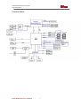
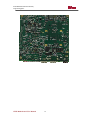
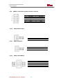
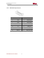
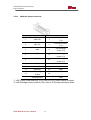
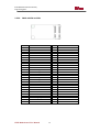
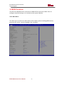
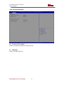
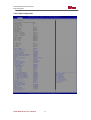
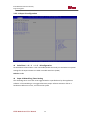
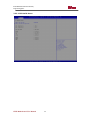
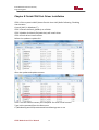
IH70 Motherboard
Mini-ITX SBC with w/ Intel® 4th Generation Core i3/i5/i7 Processor, VGA, LVDS,
Dual Giga Ethernet, USB 3.0 and Mini-PCIe Interface.
User Manual / Engineering Spec.
Version 1.0
IH70 Motherboard User Manual /
Engineering Spec.
FCC Statement
This device complies with part 15 FCC rules. Operation is subject to
the following two conditions:
This device may not cause harmful interference.
This device must accept any interference received including
interference that may cause undesired operation.
This equipment has been tested and found to comply with the limits for a class "a"
digital device, pursuant to part 15 of the FCC rules. These limits are designed to
provide reasonable protection against harmful interference when the equipment is
operated in a commercial environment. This equipment generates, uses, and can
radiate radio frequency energy and, if not installed and used in accordance with the
instruction manual, may cause harmful interference to radio communications.
Operation of this equipment in a residential area is likely to cause harmful
interference in which case the user will be required to correct the interference at him
own expense.
IH70 Motherboard User Manual
II
IH70 Motherboard User Manual /
Engineering Spec.
Copyright Notice
No part of this document may be reproduced, copied, translated, or transmitted in
any form or by any means, electronic or mechanical, for any purpose, without the
prior written permission of the original manufacturer.
Trademark Acknowledgement
Brand and product names are trademarks or registered trademarks of their
respective owners.
Disclaimer
We reserve the right to make changes, without notice, to any product, including
circuits and/or software described or contained in this manual in order to improve
design and/or performance. We assume no responsibility or liability for the use of
the described product(s), conveys no license or title under any patent, copyright, or
masks work rights to these products, and makes no representations or warranties
that these products are free from patent, copyright, or mask work right infringement,
unless otherwise specified. Applications that are described in this manual are for
illustration purposes only. Winmate Communication Inc. makes no representation or
warranty that such application will be suitable for the specified use without further
testing or modification.
Warranty
We warrant that each of its products will be free from material and workmanship
defects for a period of one year from the invoice date. If the customer discovers a
defect, We will, at its option, repair or replace the defective product at no charge to
the customer, provided it is returned during the warranty period of one year, with
transportation charges prepaid. The returned product must be properly packaged in
its original packaging to obtain warranty service.
If the serial number and the product shipping data differ by over 30 days, the
in-warranty service will be made according to the shipping date. In the serial
numbers the third and fourth two digits give the year of manufacture, and the fifth
digit means the month (e. g., with A for October, B for November and C for
December).
For example, the serial number 1W11Axxxxxxxx means October of year 2011.
IH70 Motherboard User Manual
III
IH70 Motherboard User Manual /
Engineering Spec.
Packing List
Before using this Motherboard, please make sure that all the items listed below are
present in your package:
IH70 Motherboard
HDD SATA Cable
User’s Manual & Driver DVD
If any of these items are missing or damaged, contact your distributor or sales
representative immediately.
Customer Service
We provide service guide for any problem as follow steps: The first, contact with
your distributor, sales representative, or our customer service center for technical
support if you need additional assistance. You may have the following information
ready before you call:
Product serial number
Peripheral attachments
Software (OS, version, application software, etc.)
Description of complete problem
The exact wording of any error messages
In addition, free technical support is available from our engineers every business day.
We are always ready to give advice on application requirements or specific
information on the installation and operation of any of our products. Please do not
hesitate to call or e-mail us.
IH70 Motherboard User Manual
IV
IH70 Motherboard User Manual /
Engineering Spec.
Safety Precautions
Warning!
Always completely disconnect the power cord from your chassis
whenever you work with the hardware. Do not make connections
while the power is on. Sensitive electronic components can be
damaged by sudden power surges. Only experienced electronic
personnel should open the PC chassis.
Caution!
Always ground yourself to remove any static charge before
touching the CPU card. Modern electronic devices are very
sensitive to static electric charges. As a safety precaution, use a
grounding wrist strap at all times. Place all electronic components
in a static-dissipative surface or static-shielded bag when they are
not in the chassis.
IH70 Motherboard User Manual
V
IH70 Motherboard User Manual /
Engineering Spec.
Safety and Warranty
1.
2.
3.
4.
5.
6.
7.
8.
9.
10.
11.
12.
13.
14.
15.
Please read these safety instructions carefully.
Please keep this user's manual for later reference.
Please disconnect this equipment from any AC outlet before cleaning. Do not
use liquid or spray detergents for cleaning. Use a damp cloth.
For pluggable equipment, the power outlet must be installed near the
equipment and must be easily accessible.
Keep this equipment away from humidity.
Put this equipment on a reliable surface during installation. Dropping it or
letting it fall could cause damage.
The openings on the enclosure are for air convection. Protect the equipment
from overheating. DO NOT COVER THE OPENINGS.
Make sure the voltage of the power source is correct before connecting the
equipment to the power outlet.
Position the power cord so that people cannot step on it. Do not place anything
over the power cord.
All cautions and warnings on the equipment should be noted.
If the equipment is not used for a long time, disconnect it from the power
source to avoid damage by transient over-voltage.
Never pour any liquid into an opening. This could cause fire or electrical shock.
Never open the equipment. For safety reasons, only qualified service personnel
should open the equipment.
If any of the following situations arises, get the equipment checked by service
personnel:
A. The power cord or plug is damaged.
B. Liquid has penetrated into the equipment.
C. The equipment has been exposed to moisture.
D. The equipment does not work well, or you cannot get it to work according
to the user’s manual.
E. The equipment has been dropped and damaged.
F. The equipment has obvious signs of breakage.
Do not leave this equipment in an uncontrolled environment where the storage
temperature is below -20° C (-4°F) or above 60° C (140° F). It may damage the
equipment.
IH70 Motherboard User Manual
VI
IH70 Motherboard User Manual /
Engineering Spec.
Revision History
Version
1.0
Date
2014.10.7
IH70 Motherboard User Manual
Note
Initial Draft
VII
Author
Patrick Hsien
IH70 Motherboard User Manual /
Engineering Spec.
Contents
CHAPTER 1
GENERAL INFORMATION .......................................2
1.1 INTRODUCTION ................................................................................... 2
1.2 FEATURE ............................................................................................. 2
1.3 MOTHERBOARD SPECIFICATIONS ........................................................ 3
CHAPTER 2
INSTALLATIONS.........................................................8
2.1 MEMORY MODULE(SO-DIMM)INSTALLATION ............................. 8
2.2 I/O EQUIPMENT INSTALLATION ........................................................... 9
2.2.1
12V DC-IN .......................................................................................................................... 9
2.2.2
Serial COM ports ............................................................................................................... 9
2.2.3
External VGA ..................................................................................................................... 9
2.2.4
Ethernet interface ............................................................................................................. 9
2.2.5
USB ports............................................................................................................................. 9
2.2.6
Audio function ................................................................................................................... 10
2.3 JUMPERS AND CONNECTORS ............................................................. 11
2.4 JUMPER SETTING............................................................................... 13
2.4.1
SW1:Clear CMOS ............................................................................................................... 14
2.4.2
JP1: RS232 / RS422 / RS485 Selector for COM port ........................................................... 14
2.4.3
JP2 : RS232 / RS422 / RS485 Selector for COM port .......................................................... 14
2.4.4
JP3 : Brightness Control(VR/Software) .............................................................................. 15
2.4.6
JP8 : Back Light PWR ......................................................................................................... 15
2.4.7
JP10: LCD Panel Voltage Select.......................................................................................... 15
2.4.8
JP14 : Brightness Control(DC/PWM) ................................................................................. 16
2.5 CONNECTORS AND PIN ASSIGNMENT ................................................ 17
2.5.1
CON1: LVDS Connector ...................................................................................................... 18
2.5.2
CN16: Digital Panel Backlight Inverter Connector ............................................................. 19
2.5.3
CN17: Digital Panel Backlight Brightness Control ............................................................. 19
2.5.4
CN14: Serial port COM2 .................................................................................................... 20
2.5.5
CN12,CN11:COM5、COM6 ............................................................................................... 20
2.5.6
USB1,2 : USB 2.0 Wafer ..................................................................................................... 21
2.5.7
CN27:USB 3.0 Wafer.......................................................................................................... 22
2.5.8
FAN1,FAN2:CPU & System FAN CONNECTOR .................................................................... 22
2.5.9
PANEL1: Front Panel System Function Connector.............................................................. 23
2.5.10
CN8,CN9:5V Output ........................................................................................................ 23
2.5.11
CN6:12V Output .............................................................................................................. 23
IH70 Motherboard User Manual
VIII
IH70 Motherboard User Manual /
Engineering Spec.
2.5.12
CN20: SATA POWER ......................................................................................................... 23
2.5.13
CN13:HDMI Output Connector ........................................................................................ 24
2.5.14
CN21:DVI Output Connector ........................................................................................... 25
2.5.15
CN26:eDP Output Connector........................................................................................... 26
2.5.16
CN7: Digital I/O Connector .............................................................................................. 27
2.5.17
J1,J2: Amplifier ................................................................................................................ 27
2.5.18
CN10: Mini-PCIE Half card Slot ........................................................................................ 28
2.5.19
CN18: Mini-PCIE 3G Full Card Slot ................................................................................... 29
2.5.20
CN19: mSATA card Slot .................................................................................................... 30
2.5.21
CN24: SIM Card Daughter Board Connector ................................................................... 31
2.5.22
LPT1:Printer Port ............................................................................................................. 31
CHAPTER 3 AMI BIOS SETUP ...................................................................33
3.1 HOW AND WHEN TO USE BIOS SETUP ................................................ 33
3.2 BIOS FUNCTIONS ................................................................................ 34
3.2.1 Main Menu ........................................................................................................................... 34
3.2.2 Advanced Setting.................................................................................................................. 35
3.2.3 Chipset Menu ....................................................................................................................... 51
3.2.4 Boot Menu............................................................................................................................ 57
3.2.5 Security Menu ...................................................................................................................... 58
3.2.6 Save & Exit ........................................................................................................................... 59
3.3 USING RECOVERY WIZARD TO RESTORE COMPUTER .......................... 61
CHAPTER 4 GRAPHIC DRIVER INSTALLATION .........................................64
4.1 INSTRUCTION .......................................................................................... 64
CHAPTER 5 CHIPSET DRIVER INSTALLATION ...........................................68
5.1 INSTRUCTION .......................................................................................... 68
CHAPTER 6 ETHERNET DRIVER INSTALLATION ........................................72
6.1 INSTRUCTION........................................................................................ 72
CHAPTER 7 AUDIO DRIVER INSTALLATION .............................................76
7.1 INTRODUCTION ..................................................................................... 76
7.2 INSTALLATION OF AUDIO DRIVER .............................................................. 76
CHAPTER 8 FINTEK COM PORT DRIVER INSTALLATION ..........................79
CHAPTER 9 INTEL® MANAGEMENT ENGINE SOFTWARE INSTALLATION
83
IH70 Motherboard User Manual
IX
IH70 Motherboard User Manual /
Engineering Spec.
9.1 INTRODUCTION ....................................................................................... 83
APPENDIX ..............................................................................................87
NOTE1: DIGITAL I/O SAMPLE CODE .......................................................... 87
NOTE2: WATCHDOG SAMPLE CODE .......................................................... 87
IH70 Motherboard User Manual
X
General Information
CHAPTER
IH70 Motherboard User Manual /
Engineering Spec.
1
This chapter includes the IH70 Motherboard background
information.
Sections include:
Introduction
Feature
Motherboard Specification
Function Block
Board Dimensions
IH70 Motherboard User Manual
1
IH70 Motherboard User Manual /
Engineering Spec.
Chapter 1
1.1
General Information
Introduction
The IH70 SBC is integrated with Intel®QM87 chipset, 17x17mm, and Socket
G3 Intel® 4th Generation Core i7i5/i3 Processor. The Intel®4th Generation Core™
processor based on 64-bit, multi-core processors built on 22-nanometer
process technology.
The processors are designed for a two-chip platform consisting of a processor
and Platform Controller Hub (PCH). The processors are designed to be used
with the Mobile chipset.
In peripheral connectivity, IH70 SBC features with three Mini-PCIe I/O ports, ,
two Serial ATA III (6Gb/s)connectors, six Serial Port (Three Connector; Three
Pin Header ) ,six Super-Speed USB 3.0 connectors(Four Connector ; Two Pin
Header ) and four Hi-Speed USB 2.0 connectors(Four Pin Header ) .Additionally,
IH70 SBC build-in a 12V DC-IN power adapter.
Thus, the IH70 SBC is designed to satisfy most of the applications in the
industrial computer market, such as Gaming, POS, KIOSK, Industrial
Automation, and Programmable Control System. It is a compact design to
meet the demanding performance requirements of today’s business and
industrial applications.
1.2
Feature
Mini-ITX Form Factor ( 170mm x 170mm)
Supports Socket G3 Intel® 4th Generation Core i3/i5/i7 Processor
System memory up to 16GB DDR3L 1333/1600, SO-DIMM
Intel®QM87 Chipset
Intel® HD Graphics 4600. Integrated Graphics Engine.
Intel® I210IT Gigabit-LAN Controller + I218LM Gigabit-LAN PHY r
3 x Mini PCIe, 6 x COM, 6 x USB3.0, 4 x USB 2.0 ,2 x SATAIII, 8 x GPIO
ports, 1 x HDMI,1xeDP(By BOM Option),1 x PCIe x 16, 1 x LPT port
IH70 Motherboard User Manual
2
IH70 Motherboard User Manual /
Engineering Spec.
1.3
Motherboard Specifications
CPU Type
Chipset
BIOS
Graphic
LCD interface
Resolution
Multiple Display
LAN
Memory Type
Super I/O
Sound
USB
Edge Connectors
On Board
Pin-Header
Connectors
Power Connector
Expansion Slots
Form Factor
Dimensions
Intel® 4th Generation Core i3/i5/i7 Processor
Intel® QM87
AMI System BIOS
Intel® HD Graphics 4600 support DX11, OGL4.0
Dual-channel 24 bit LVDS Up to 1440 x 900 @ 60Hz
VGA mode: Up to 1920 x 1200 @ 60Hz
DVI: 1920 x 1200 @ 60Hz
HDMI: 1920 x 1200 @ 60Hz
LVDS : 1920 x 1200 @ 60Hz ;co-lay eDP(by BOM Option)
VGA+LVDS(eDP)+HDMI,VGA+LVDS(eDP)+DVI,VGA+HDMI+DVI,
HDMI+LVDS(eDP)+DVI,VGA+HDMI+HDMI,VGA+DVI+DVI,
LVDS(eDP)+HDMI+HDMI, LVDS(eDP)+DVI+DVI
2 x Giga LAN (Intel® I210IT Gigabit-LAN Controller + I218LM
Gigabit-LAN PHY )
2 x SO-DIMM socket, supports up to 16GB DDR3L 1333/1600
Fintek F81867
Realtek ALC886 HD Audio Codec
6 ports, USB 3.0 (4 x USB Connector, 2 x USB pin-header )
4 ports, USB 2.0 (4 x USB pin-header )
1 x DC-IN Jack (+12V)
1 x VGA out connector
2 x Gigabit LAN RJ-45
1 x RS232/422/485
2 x RS232
4 x USB 3.0 connector
2 x PS2
1 x Audio Jack(Line in, Line out, Mic in)
3 x RS-232 (COM2.COM5.COM6) 2x5 pin-header
4 x USB 2.0
2 x USB3.0
1 x DVI/HDMI by DF-13 20-pin connector
1 x LVDS by DF-13 40-pin connector
1 x eDP by DF-13 20-pin connector(Optional)
2 x SATA III
1 x 2x4-pin wafer for SATA power
2 x 2-pin pin-header for speaker (with Amplifier): Left, Right
1 x 10-pin pin-header for DIO
1 x 3-pin digital panel backlight brightness controller
1 x 7-pin inverter
1 x 2x2-pin DC-in 12V connector
1 x 10-pin wafer for Front Panel(2x5)
2 x 2-pin wafer for +5V external power (Red)
1 x 2-pin wafer for 12V external power (Yellow)
1 x 3-pin pin-header for CPU Fan (smart fan)
1 x 20-pin box header for LPT Port
1 x 6-pin wafer for external SIM Card daughter board
Input: 4-pin Power-input connector
3 x Mini PCIe slot
1 x PCIe x 16 slot
Mini-ITX
170mm x 170mm
IH70 Motherboard User Manual
3
IH70 Motherboard User Manual /
Engineering Spec.
Mechanical &
environmental
Operating temperature: 0 deg. C to 60 deg. C
Shock: Operating 15G, 11ms duration
Vibration: Operating 5 Hz~500Hz / 1Grms / 3 Axis
Certification: CE, FCC, RoHS
IH70 Motherboard User Manual
4
IH70 Motherboard User Manual /
Engineering Spec.
Function Block
IH70 Motherboard User Manual
5
IH70 Motherboard User Manual /
Engineering Spec.
Board dimensions
IH70 Motherboard User Manual
6
Installations
CHAPTER
IH70 Motherboard User Manual /
Engineering Spec.
2
This chapter provides information on how to use the
jumps and connectors on the IH70 Motherboard.
The Sections include:
Memory Module Installation
I / O Equipment Installation
Setting the Jumpers
Connectors on IH70 Motherboard
IH70 Motherboard User Manual
7
IH70 Motherboard User Manual /
Engineering Spec.
Chapter 2
Installations
2.1 Memory Module(
(SO-DIMM)
)Installation
The IH70 Motherboard provides two 204-pin SODIMM slot. The socket supports up
to 16GB DDR3L 1333/1600 SDRAM. When installing the Memory device, please follow
the steps below:
Step.1. Firmly insert the SO-DIMM at an angle into its slot. Align the SO-DIMM on the
slot such that the notch on the SO-DIMM matches the break on the slot.
Step.2. Press downwards on SO-DIMM until the retaining clips at both ends fully snap
back in place and the SO-DIMM is properly seated.
Caution!
The SO-DIMM only fits in one correct orientation. It will cause
permanent damage to the development board and the SO-DIMM if
the SO-DIMM is forced into the slot at the incorrect orientation.
IH70 Motherboard User Manual
8
IH70 Motherboard User Manual /
Engineering Spec.
2.2 I/O Equipment Installation
2.2.1
12V DC-IN
The Motherboard allows plugging 12V DC-IN jack on the board without another
power module converter under power consumption by Intel® 4th Generation Core
i7/i5/i3 Processor and QM87 chipset.
2.2.2
Serial COM ports
Three RS-232 connectors build in the rear I/O. One optional COM ports support
RS-422/485. When an optional touch-screen is ordered with PPC, serial com port can
connect to a serial or an optional touch-screen.
2.2.3
External VGA
The Motherboard has one VGA port that can be connected to an external CRT/ LCD
monitor. Use VGA cable to connect to an external CRT / LCD monitor, and connect
the power cable to the outlet. The VGA connector is a standard 15-pin D-SUB
connector.
2.2.4
Ethernet interface
The Motherboard is equipped with Intel® I210IT Gigabit-LAN Controller + I218LM
Gigabit-LAN PHY which is fully compliant with the PCI 10/100/1000 Mbps Ethernet
protocol compatible. It is supported by major network operating systems. The
Ethernet ports provide two standard RJ-45 jacks.
2.2.5
USB ports
Eight USB devices (Four with pin headers) may be connected to the system though an
adapter cable. Various adapters may come with USB ports. USB usually connect the
external system to the system. The USB ports support hot plug-in connection.
Whatever, you should install the device driver before you use the device.
IH70 Motherboard User Manual
9
IH70 Motherboard User Manual /
Engineering Spec.
2.2.6
Audio function
The Audio 7.1 channel capabilities are provided by a Realtek ALC886 chipset
supporting digital audio outputs. The audio interface includes three jacks: line-in,
line-out and mic in.
IH70 Motherboard User Manual
10
IH70 Motherboard User Manual /
Engineering Spec.
2.3 Jumpers and Connectors
TOP
Front Panel
SATA1
SATA2
SATA PWR
CN23
SO-DIMM
Inverter
JP8
JP14
USB 3.0
mSATA card Slot
Mini-PCIE Full
Card
LVDS
USB 2.0
System Fan
JP10
COM6
eDP
COM5
COM2
DVI
HDMI
CPU Fan
LPT port
Mini-PCIE Half
JP2
DIO
12V
Card
SPK
JP1
5V
11
RJ45
USB 3.0
Audio
IH70 Motherboard User Manual
COM1
PS2
12V DC in
COM4
COM3
IH70 Motherboard User Manual /
Engineering Spec.
IH70 Motherboard User Manual
12
IH70 Motherboard User Manual /
Engineering Spec.
2.4 Jumper Setting
A pair of needle-nose pliers may be helpful when working with jumpers. If you have
any doubts about the best hardware configuration for your application, contact your
local distributor or sales representative before you make any changes. Generally, you
simply need a standard cable to make most connections.
The jumper setting diagram is as below. If a jumper shorts pin 1 and pin 2, the setting
diagram is shown as the right one.
1
2
3
The following tables list the function of each of the board's jumpers.
Label
Function
SW1
Clear CMOS
JP1
RS232 / RS422 / RS485 Selector
3x4 header , pitch 2.0mm
JP2
RS232 / RS422 / RS485 Selector
2x3 header , pitch 2.0mm
JP3
VR/Software
2x3 header , pitch 2.0mm
JP8
Back Light PWR
1x3 header , pitch 2.0mm
JP10
LVDS PWR Selector
2x3 header , pitch 2.5mm
JP14
PWM/DA
3x1 header , pitch 2.0mm
IH70 Motherboard User Manual
Note
13
IH70 Motherboard User Manual /
Engineering Spec.
2.4.1
SW1:Clear CMOS
2.4.2
JP1: RS232 / RS422 / RS485 Selector for COM port
2.4.3
JP2 : RS232 / RS422 / RS485 Selector for COM port
IH70 Motherboard User Manual
14
IH70 Motherboard User Manual /
Engineering Spec.
2.4.4
JP3 : Brightness Control(VR/Software)
2.4.6
JP8 : Back Light PWR
2.4.7
JP10: LCD Panel Voltage Select
IH70 Motherboard User Manual
15
IH70 Motherboard User Manual /
Engineering Spec.
2.4.8
JP14 : Brightness Control(DC/PWM)
IH70 Motherboard User Manual
16
IH70 Motherboard User Manual /
Engineering Spec.
2.5 Connectors and Pin Assignment
The table below lists the function of each of the board’s connectors.
Label
Function
Note
CON1
LVDS Connector
40DP-1.25V
CN16
Digital Panel Backlight Inverter Connector
7x1 Wafer, pitch 2.0mm
CN17
Digital Panel Backlight Brightness Control
3x1 Wafer, pitch 2.0mm
CN14
COM2 for RS232
2x5 header, pitch 2.0mm
CN12,CN11
COM5、6 for RS232
2x5 header, pitch 2.0mm
USB1,2
USB 2.0 Connector
4x2 Wafer, pitch 2.0mm
CN27
USB 3.0 Connector
5x2 Wafer, pitch 2.0mm
FAN1
CPU Fan CONNECTOR
3x1 Pin Header
FAN2
System Fan Connector
3x1 Pin Header
PANEL1
System Function Connector
5x2 header ,pitch 2.0mm
CN6
12V External Power
2x1 header, pitch 2.0mm
CN8.CN9
5V External Power
2x1 header, pitch 2.0mm
CN20
SATA Power Connector
4x2 header ,pitch 2.54mm
CN13
HDMI Output Connector
20DP-1.25V
CN21
DVI Output Connector
20DP-1.25V
CN26
eDP Output Connector
20DP-1.25V
CN7
Digital I/O
2x5 Pin header, pitch 2.0mm
J1,J2
Speaker(Right/Left)
2x1 Wafer, pitch 2.0mm
CN10
Mini-PCIE Half card Slot
mini-PCIE slot, H:6.8mm
CN18
Mini-PCIE 3G Full Card Slot
mini-PCIE slot, H:6.8mm
CN19
mSATA card Slot
mini-PCIE slot, H:6.8mm
CN24
SIM Card Daughter Board Connector
6x1 Wafer, pitch 1.25mm
LPT1
Printer Port
2x10 header, pitch 2.0mm
* Not Default Connector
IH70 Motherboard User Manual
17
IH70 Motherboard User Manual /
Engineering Spec.
2.5.1
CON1: LVDS Connector
Pin No.
1
SYMBOL
LCDVDD
Pin No.
2
LVDSA_DATA0-
3
LCDVDD
4
LVDSA_DATA0+
5
LCDVDD
6
LVDSA_DATA1-
7
GND
8
LVDSA_DATA1+
9
GND
10
LVDSA_DATA2
11
GND
12
LVDSA_DATA2
13
GND
14
LVDSA_CLK-
15
GND
16
LVDSA_CLK+
17
GND
18
LVDSA_DATA3
19
GND
20
LVDSA_DATA3
21
GND
22
LVDSBDATA0-
23
GND
24
LVDSBDATA0+
25
GND
26
LVDSBDATA1-
27
GND
28
LVDSBDATA1+
29
GND
30
LVDSBDATA2-
31
GND
32
LVDSBDATA2+
33
GND
34
LVDSBCLK-
35
GND
36
LVDSBCLK+
37
GND
38
LVDSBDATA3
39
GND
40
LVDSBDATA3
*LCDVCC select by JP10
IH70 Motherboard User Manual
18
SYMBOL
IH70 Motherboard User Manual /
Engineering Spec.
2.5.2
CN16: Digital Panel Backlight Inverter Connector
Pin No.
1
2
3
4
5
6
7
SYMBOL
VCC
VCC
VCC
GND
Black Light Control
GND
Black Light EN 5V
*Vcc level select by JP8
2.5.3
CN17: Digital Panel Backlight Brightness Control
Pin No.
1
2
3
IH70 Motherboard User Manual
SYMBOL
VCC
Black Light Control
GND
19
IH70 Motherboard User Manual /
Engineering Spec.
2.5.4
CN14: Serial port COM2
Pin
10
8
6
4
2
SYMBOL
+V5S
NRI2
NCTS2
NRTS2
NDSR2
2.5.5
CN12,CN11:COM5、
、COM6
Pin
9
7
5
3
1
SYMBOL
GND
NDTR2
NTXD2
NRXD2
NDCD2
The serial port COM5、6, which is RS232 only , is the Fintek I/O serial port.
5x2 header, pitch 2.0mm
Pin No.
SYMBOL
10
+V5S
Pin No.
SYMBOL
9
GND
8
FK NRI5
7
FK NDTR5
6
FK NCTS5
5
FK NSOUT5
4
FK NRTS5
3
FK NSIN5
2
FK NDSR5
1
FK NDCD5
IH70 Motherboard User Manual
20
IH70 Motherboard User Manual /
Engineering Spec.
Pin No.
SYMBOL
20
+V5S
Pin No.
SYMBOL
19
GND
18
FK NRI6
17
FK NDTR6
16
FK NCTS6
15
FK NSOUT6
14
FK NRTS6
13
FK NSIN6
12
FK NDSR6
11
FK NDCD6
2.5.6
USB1,2 : USB 2.0 Wafer
2
1
4
3
6
5
8
7
IH70 Motherboard User Manual
Pin
2
4
6
8
SYMBOL
USBVCC
USB_P6USB_P6+
GND
21
Pin
1
3
5
7
SYMBOL
USBVCC
USB_P7USB_P7+
GND
IH70 Motherboard User Manual /
Engineering Spec.
2.5.7
CN27:USB 3.0 Wafer
Pin
2
4
6
8
10
12
14
16
18
20
2.5.8
SYMBOL
NC
USBVCC
USB3.0 RX4USB3.0 RX4GND
USB3.0 TX4USB3.0 TX4GND
USB_P7USB_P7+
Pin
1
3
5
7
9
11
13
15
17
19
SYMBOL
USBVCC
USB3.0 RX3USB3.0 RX3+
GND
USB3.0 TX3USB3.0 TX3+
GND
USB_P6USB_P6+
NC
FAN1,FAN2:CPU & System FAN CONNECTOR
Pin
1
3
Pin
1
3
IH70 Motherboard User Manual
SYMBOL
GND
CPU FAN
Sense
Pin
2
SYMBOL
+12V
SYMBOL
GND
System FAN
Sense
Pin
2
SYMBOL
+12V
22
IH70 Motherboard User Manual /
Engineering Spec.
2.5.9
2
4
6
8
10
2.5.10
PANEL1: Front Panel System Function Connector
1
3
5
7
9
Pin
2
4
6
8
10
SYMBOL
HD_LED+
HD_LEDRT_BT1
RT_BT2
5VSB
SYMBOL
GND
Pin
1
SYMBOL
VCC
CN6:12V Output
Pin
2
2.5.12
SYMBOL
PW_LED+
PW_LEDPW_BT1
PW_BT2
RSEV
CN8,CN9:5V Output
Pin
2
2.5.11
Pin
1
3
5
7
9
SYMBOL
GND
Pin
1
SYMBOL
+12V
CN20: SATA POWER
Pin
2
4
6
8
IH70 Motherboard User Manual
SYMBOL
+12V
GND
GND
+5V
23
Pin
1
3
5
7
SYMBOL
+12V
GND
GND
+5V
IH70 Motherboard User Manual /
Engineering Spec.
2.5.13
CN13:HDMI Output Connector
Pin No.
1
SYMBOL
GND
Pin No.
2
SYMBOL
HDMI_TMDS2-
3
GND
4
HDMI_TMDS2+
5
GND
6
HDMI_TMDS1-
7
GND
8
HDMI_TMDS1+
9
GND
10
HDMI_TMDS0-
11
HDMI HPD
12
HDMI_TMDS0+
13
NC
14
HDMI_CLK-
15
NC
16
HDMI_CLK+
17
HDMI 5V
18
HDMI_DDC_CLK
19
HDMI 5V
20
HDMI_DDC_DATA
IH70 Motherboard User Manual
24
IH70 Motherboard User Manual /
Engineering Spec.
2.5.14
CN21:DVI Output Connector
Pin No.
1
SYMBOL
GND
Pin No.
2
TMDSB_DATA0-
3
GND
4
TMDSB_DATA0+
5
DVIC_LVDS_DET
6
TMDSB_DATA1-
7
DVIC_BKLTEN
8
TMDSB_DATA1+
9
DVIC_VDDEN
10
TMDSB_DATA2-
11
DVI_HOT_DETECT
12
TMDSB_DATA2+
13
LCDVDD
14
TMDSB_BLK-
15
LCDVDD
16
TMDSB_BLK+
17
+V5S
18
DVI1_DDC_CLK_R
19
+V5S
20
DVI_DDC_DAT_R
IH70 Motherboard User Manual
25
SYMBOL
IH70 Motherboard User Manual /
Engineering Spec.
2.5.15
CN26:eDP Output Connector
Pin No.
SYMBOL
Pin No.
1
eDP Tx0+
2
3
eDP Tx0-
4
5
GND
6
7
9
eDP Tx1+
8
eDP Tx1-
10
SYMBOL
eDP Panel Power
(*1)
eDP Panel Power
(*1)
eDP Backlight
Power (*2)
eDP Backlight
Power (*2)
eDP Backlight
Power (*2)
11
GND
12
eDP HPD
13
eDP AUX+
14
GND
15
eDP AUX-
16
GND
17
eDP Backlight
Enable
18
19
eDP Brightness
20
GND
GND
*1: eDP Panel Power select by JP10, refer to JP10 jumper setting for detail.
*2: eDP Backlight power select by JP8, refer to JP8 jumper setting for detail.
IH70 Motherboard User Manual
26
IH70 Motherboard User Manual /
Engineering Spec.
2.5.16
CN7: Digital I/O Connector
Pin
2
4
6
8
10
2.5.17
J1,J2: Amplifier
J2
J1
IH70 Motherboard User Manual
27
SYMBOL
+5V
Out1
Out0
IN2
IN0
Pin
1
3
5
7
9
SYMBOL
GND
Out3
Out2
IN3
IN1
IH70 Motherboard User Manual /
Engineering Spec.
2.5.18
CN10: Mini-PCIE Half card Slot
Pin
1
3
5
7
9
11
13
15
17
19
21
23
25
27
29
31
33
35
37
39
41
43
45
47
49
51
m1
m2
SYMBOL
PCIE_WAKE#
NC
NC
SLOT0_OE#
GND
CLK_PCIE_SLOT0_N
CLK_PCIE_SLOT0_P
GND
NC
NC
GND
PCIE_RXN1_SLOT1
PCIE_RXP1_SLOT1
GND
GND
PCIE_TXN1_SLOT1
PCIE_TXP1_SLOT1
GND
GND
+3.3Vaux
+3.3Vaux
GND
CL_CLK
CL_DATA
CL_RST#
+V3.3_WIFI
GND
GND
IH70 Motherboard User Manual
Pin
2
4
6
8
10
12
14
16
18
20
22
24
26
28
30
32
34
36
38
40
42
44
46
48
50
52
m1
m2
28
SYMBOL
+V3.3_WIFI
GND
+V1.5V
NC
NC
NC
NC
NC
GND
WiFi_EN
BUF2_PLT_RST#
+3.3Vaux
GND
+1.5V
SMB_CLK_SB
SMB_DATA_SB
GND
USB_PN10
USB_PP10
GND
NC
NC
NC
+1.5VS
GND
+V3.3_WIFI
GND
GND
IH70 Motherboard User Manual /
Engineering Spec.
2.5.19
CN18: Mini-PCIE 3G Full Card Slot
Pin
1
3
5
7
9
11
13
15
17
19
21
23
25
27
29
31
33
35
37
39
41
43
45
47
49
51
m1
m2
SYMBOL
PCIE_WAKE#
NC
NC
CLK_SLOT1_OE#
GND
CLK_PCIE_SLOT1_N
CLK_PCIE_SLOT1_P
GND
NC
NC
GND
PCIE_RXN1_SLOT2
PCIE_RXP1_SLOT2
GND
GND
PCIE_TXN1_SLOT2
PCIE_TXP1_SLOT2
GND
GND
3V_GOBI_AUX
3V_GOBI_AUX
GND
NC
NC
NC
NC
GND
GND
IH70 Motherboard User Manual
Pin
2
4
6
8
10
12
14
16
18
20
22
24
26
28
30
32
34
36
38
40
42
44
46
48
50
52
m1
m2
29
SYMBOL
+V3.3_3G
GND
+V1.5S
VREG_USIM
USIM_DATA
USIM_CLK
USIM_RESET
USIM_VPP
GND
3G-RFON
BUF1_PLT_RST#
3V_GOBI_AUX
GND
+V1.5S
SMB_CLK_SB
SMB_DATA_SB
GND
USB_PN11
USB_PP11
GND
NC
NC
NC
+V1.5S
GND
+V3.3_3G
GND
GND
IH70 Motherboard User Manual /
Engineering Spec.
2.5.20
CN19: mSATA card Slot
Pin
1
3
5
7
9
11
13
15
17
19
21
23
25
27
29
31
33
35
37
39
41
43
45
47
49
51
m1
m2
SYMBOL
NC
NC
NC
NC
GND
NC
NC
GND
NC
NC
GND
SATA_RXP1
SATA_RXN1
GND
GND
SATA_TXN1
SATA_TXP1
GND
GND
+V3.3S
+V3.3S
GND
NC
NC
SSD_LED#
EC_BT_EN
GND
GND
IH70 Motherboard User Manual
Pin
2
4
6
8
10
12
14
16
18
20
22
24
26
28
30
32
34
36
38
40
42
44
46
48
50
52
m1
m2
30
SYMBOL
+3.3S
GND
+1.5V
NC
NC
NC
NC
NC
GND
NC
PLTRST#
+3.3S
GND
+1.5V
NC
NC
GND
NC
NC
GND
NC
NC
NC
+1.5V
GND
+3.3V
GND
GND
IH70 Motherboard User Manual /
Engineering Spec.
2.5.21
CN24: SIM Card Daughter Board Connector
Pin
1
2
3
4
5
6
2.5.22
SYMBOL
VREG_USIM
USIM_RESET
USIM_CLK
GND
USIM_VPP
USIM_DATA
LPT1:Printer Port
Pin Number
1
3
5
7
9
11
13
15
17
19
IH70 Motherboard User Manual
SYMBOL
LPT_STB#
LPT_PD1
LPT_PD3
LPT_PD5
LPT_PD7
BUSY
SLCT
ERR#
LPT_SLIN#
GND
31
Pin Number
2
4
6
8
10
12
14
16
18
20
SYMBOL
LPT_PD0
LPT_PD2
LPT_PD4
LPT_PD6
ACK#
PE
LPT_AFD#
LPT_INIT#
GND
GND
AMI BIOS Setup
CHAPTER
IH70 Motherboard User Manual /
Engineering Spec.
1. Instruction
2. BIOS configuration
3. Using Recovery Wizard to Restore Computer
IH70 Motherboard User Manual
32
3
IH70 Motherboard User Manual /
Engineering Spec.
Chapter 3 AMI BIOS SETUP
3.1 How and When to Use BIOS Setup
For enter to the Tablet PC BIOS setup, you need to connect with an external USB
keyboard, press “Del” key when the prompt appears on the screen during start up.
The prompt screen shows only few seconds so need press Del key quickly.
**NOTICE
Updated BIOS version may be published after the manual is released. Check with the
latest version of BIOS on website.
You may need to run BIOS setup utility when the below status.
1. Error message on sreen indicate to check BIOS setup.
2. Restoring the factory default settings.
3. Modifing the specific hardware specification
4. Want to optimize the specification.
In order to control the keyboard to select BIOS utility setup, you need
Keyboard Icon
Function Description
Selects a menu title.
Selects an item or option.
Enter
Go to the sub-menu when available.
Opens or closes the option window when an item is selected.
Esc
To leave sub-menu and return to main menu.
**NOTICE
You can press the F1, F2, F3, F4, –/+, and Esc keys by connecting a USB keyboard to
your tablet PC.
IH70 Motherboard User Manual
33
IH70 Motherboard User Manual /
Engineering Spec.
3.2 BIOS Functions
The IH70 has AMI BIOS built in and with a CMOS SETUP utility that allows users to
configure required settings or to activate certain system features.
3.2.1 Main Menu
The Main menu contains the information of the Tablet system including BIOS version,
processor RC version, system language, time, and date.
IH70 Motherboard User Manual
34
IH70 Motherboard User Manual /
Engineering Spec.
3.2.2 Advanced Setting
Select the Advanced tab from the IH70 setup menu to enter the Advanced
BIOS Setup screen. You can select any of the items in the left frame of the screen,
such as CPU Configuration, to go to the sub menu for that item. You can
use the <Arrow> keys enter all Advanced BIOS Setup options. The Advanced BIOS
Setup menu is shown below. The sub menus are described on the following pages.
IH70 Motherboard User Manual
35
IH70 Motherboard User Manual /
Engineering Spec.
3.2.2.1 PCI Express Device Register Settings
Relaxed Ordering
Enable or disable Relaxed Ordering
Extended Tag
Enable or disable Extended Tag
No Snoop
Enable or disable No Snoop
Maximum Payload
To set the Maximum Payload.
Maximum Read Request
To set the Maximum Read Request
ASPM Support
Enable or disable ASPM Support
Extended Synch
Enable or disable Extended Synch
Link Training Retry
To set the Link Training Retry
IH70 Motherboard User Manual
36
IH70 Motherboard User Manual /
Engineering Spec.
Link Training Timeout (uS)
To set the Link Training Timeout(uS)
Unpopulated Links
To set the Unpopulated Links
Restore PCIE Registers
Enable or disable Restore PCIE Registers
IH70 Motherboard User Manual
37
IH70 Motherboard User Manual /
Engineering Spec.
3.2.2.2 ACPI Settings
Enable ACPI Auto Configuration
Enable or disable BIOS ACPI Auto Configuration
Enable Hibernation
To enable or disable hibernation
IH70 Motherboard User Manual
38
IH70 Motherboard User Manual /
Engineering Spec.
3.2.2.3 Trusted Computing
Security Device Support
Enable or disable BIOS support for security device.
TPM State
Enable or disable TPM state.
IH70 Motherboard User Manual
39
IH70 Motherboard User Manual /
Engineering Spec.
3.2.2.4 S5 RTC Wake Settings
Wake system with Fixed Time
System wake on alarm event..When enabled, System will wake on the hr: min: sec specified.
Wake system with Dynamic Time
Options: Enabled, Disabled
IH70 Motherboard User Manual
40
IH70 Motherboard User Manual /
Engineering Spec.
3.2.2.5 CPU Configuration
IH70 Motherboard User Manual
41
IH70 Motherboard User Manual /
Engineering Spec.
3.2.2.6 Thermal Configuration
IH70 Motherboard User Manual
42
IH70 Motherboard User Manual /
Engineering Spec.
3.2.2.7 SATA Configuration
SATA Controller(s)
Allows users to enable or disable the SATA controller(s).
SATA Mode Selection
Allows users to select mode of SATA controller(s).
Aggressive LPM Support
Allows users to enable or disable the Aggerssive LPM Support.
SATA Controller Speed
Allows users to select mode of SATA Controller Speed.
Serial ATA Port 0/1/4
Allows users to enable or disable the SATA Port.
Hot Plug
Allows users to enable or disable the Hot Plug.
SATA Device type
Allows users to select mode of SATA Device type.
IH70 Motherboard User Manual
43
IH70 Motherboard User Manual /
Engineering Spec.
3.2.2.8 INTEL Rapid Star Technology
Intel® Rapid start technology
Allows users to enable or disable Intel rapid start technology.
IH70 Motherboard User Manual
44
IH70 Motherboard User Manual /
Engineering Spec.
3.2.2.9 PCH(FW) Configuration
Me FW Image Re-Flash
This item allows users to enable or disable Me FW image re-flash function.
IH70 Motherboard User Manual
45
IH70 Motherboard User Manual /
Engineering Spec.
3.2.2.10 USB Configuration
Legacy USB support
Enables Legacy USB support. AUTO option disable legacy support if no USB devices are
connected. DISABLE option will keep USB devices available only for EFI applications.
USB 3.0 Support
Allows users to enable or disable USB3.0 function
XHCI Hand-off
This is a workaround for OS without XHCI hand-off support. The XHCI ownership
change should claim by XHCI driver.
ECHI Hand-off
This is a workaround for OSes without EHCI hand-off support. The EHCI ownership change
should be claimed by EHCI driver.
Default: Disabled
USB transfer time-out
The time-out value for control, bulk, and Interrupt transfers.
Default: 20 sec
Device reset time-out
The USB mass storage device Start Unit command time-out.
Default: 20 sec
IH70 Motherboard User Manual
46
IH70 Motherboard User Manual /
Engineering Spec.
Device power-up delay
Maximum time the device will take before it properly reports itself to the Host
Controller. ’Auto’ uses default value: for a Root port it is 100 ms, for a Hub port the delay is
taken from Hub descriptor.
Mass Storage Device:
Mass storage device emulation type. ‘AUTO’ enumerates devices less than 530MB as floppies.
Forced FDD option can be used to force HDD formatted drive to boot as FDD.
IH70 Motherboard User Manual
47
IH70 Motherboard User Manual /
Engineering Spec.
3.2.2.11 Super IO configuration
Serial Port 1、
、2、
、3 、4、
、5、
、6 Configuration
Set Parameters of Serial Ports. User can Enable/Disable the serial port and Select an optimal
settings for the Super IO Device. Enable or Disable Serial Port (COM)
Default: Enable
Super IO Watch Dog Timer Setting
The watchdog timer circuit has to be triggered within a specified time by the application
software. If the watchdog is not triggered because proper software execution fails or a
hardware malfunction occurs, it will reset the system
IH70 Motherboard User Manual
48
IH70 Motherboard User Manual /
Engineering Spec.
3.2.2.12 PC Health Status
IH70 Motherboard User Manual
49
IH70 Motherboard User Manual /
Engineering Spec.
3.2.2.14 SuperIO GPIO Setting
IH70 Motherboard User Manual
50
IH70 Motherboard User Manual /
Engineering Spec.
3.2.3 Chipset Menu
PCI Express Configuration
Detail of PCI Express items.
USB Configuration
Details of USB items.
PCH Azalia Configuration
Details of PCH azalia items.
PCH LAN controller
Enables or disables the LAN1/2 controller.
Wake On LAN
Enables or disables LAN1/2 wake up from sleep state.
SLP_S4 Assertion Width
Sets a minimum assertion width for the SLP_S4# signal.
Restore AC Power Loss
This item allows users to select off, on and last state.
IH70 Motherboard User Manual
51
IH70 Motherboard User Manual /
Engineering Spec.
3.2.3.1 PCI Express Configuration
DMI Link ASPM Control
Allows users to enable or disable the DMI Link ASPM Control.
DMI Link Extended Synch Control
Allows users to configure Mini PCI Express setting.
PCIe- USB Glitch W/A
For bad USB devices connected behind PCIE/PEG port.
IH70 Motherboard User Manual
52
IH70 Motherboard User Manual /
Engineering Spec.
3.2.3.2 USB Configuration
USB Precondition
Allows user to enable or disable USB Precondition.
XHCI Mode
Allows user to enable or disable XHCI Mode.
USB Ports Per-Port Disable Control
Control each of the USB ports (0~13) disabling.
IH70 Motherboard User Manual
53
IH70 Motherboard User Manual /
Engineering Spec.
3.2.3.3 PCH Azalia Configuration
Azalia
Allows user to enable or disable azalea device.
IH70 Motherboard User Manual
54
IH70 Motherboard User Manual /
Engineering Spec.
3.2.3.4 System Agent (SA) Configuration
VT-d
Allows users to enable or disable VT-d.
IH70 Motherboard User Manual
55
IH70 Motherboard User Manual /
Engineering Spec.
3.2.3.5 Graphic Configuration
Graphics Turbo IMON Current
Allows users to select which Graphics Turbo IMON Current.
Internal Graphics
Allows users to enable or disable IGD.
Aperture Size
This item allows users to select aperture size.
DVMT Pre-Allocated
Allows users to select DVMT pre-allocated memory size.
DVMT Total Gfx Mem
Allows users to select DVMT total memory size.
Gfx Low Power Mode
Allows users to enable or disable IGD low power mode.
Panel Power Enable
Allows users to enable or disable Panel Power.
IH70 Motherboard User Manual
56
IH70 Motherboard User Manual /
Engineering Spec.
3.2.4 Boot Menu
Setup Prompt Timeout
Allows you to change number of seconds to wait for setup activation key.
Bootup NumLock State
Select the Power-on state for Numlock.
Quiet Boot
If this option is set to Disabled, the BIOS display normal POST messages. If
Enabled, an OEM Logo is shown instead of POST messages.
FAST Boot
Allows users to enable or disable Fast Boot.
Boot Order Priorities
Set the system boot order.
CSM parameters
This section allows you to configure the boot settings.
IH70 Motherboard User Manual
57
IH70 Motherboard User Manual /
Engineering Spec.
3.2.5 Security Menu
This section allows you to configure and improve your system and allows
you to set up some system features according to your preference.
IH70 Motherboard User Manual
58
IH70 Motherboard User Manual /
Engineering Spec.
3.2.6 Save & Exit
Save Changes and Exit
Allows you to exit system setup after saving changes.
Discard Changes and Exit
Allows you to exit system setup without saving any changes.
Save Changes and Reset
Allows you to reset the system after saving the changes.
Discard Changes and Reset
Allows you to rest system setup without saving any changes.
Save Changes
Allows you to save changes done so far to any of the options.
Discard Changes
Allows you to discard changes done so far to any of the options.
Restore Defaults
Allows you to restore/load default values for all the options.
Save as User Defaults
Allows you to save the changes done so far as user defaults.
IH70 Motherboard User Manual
59
IH70 Motherboard User Manual /
Engineering Spec.
Restore User Defaults
Allows you to restore the user defaults to all the options.
Boot Override
Boot device selection can override your boot priority.
IH70 Motherboard User Manual
60
IH70 Motherboard User Manual /
Engineering Spec.
3.3 Using Recovery Wizard to Restore Computer
IH70 computer has a dedicate recovery partition stored on the hard drive of the PC to enable
quick one-key recovery process. This partition occupies about 11GB of the storage space, and
comes built-in to each IH70 series PC.
Warning: Before starting the recovery process, be sure to backup all user data, as all data will
be lost after the recovery process.
Follow the procedure below to enable quick one-key recovery procedure:
• Plug-in the AC adapter to Bay Trail series computer. Make sure the computer
stays plugged in to power source during the recovery process.
• Turn on the computer, and when the boot screen shows up, press the F6 to
initiate the Recovery Wizard.
• The following screen shows the Recovery Wizard. Click on “Recovery” button to
continue.
A warning message about data loss will show up. Make sure data is backed up
before recovery, and click on “Yes” to continue.
IH70 Motherboard User Manual
61
IH70 Motherboard User Manual /
Engineering Spec.
Wait till the recovery process to complete. During the recovery process, a command
prompt will show up to indicate the percent of recovery process. After recovery is
completed, and the tablet computer will restart automatically.
IH70 Motherboard User Manual
62
CHAPTER
IH70 Motherboard User Manual /
Engineering Spec.
4
Graphic Driver Installation
This chapter offers information on the chipset software
Installation utility
Sections include:
Installation of Graphic Driver
Panel Resolution Setting
IH70 Motherboard User Manual
63
IH70 Motherboard User Manual /
Engineering Spec.
Chapter 4 Graphic Driver Installation
4.1 Instruction
IH70 Motherboard is with Intel mobile Core i7, Core i5, Core i3 dual core CPU and
with an integrated graphics controller. You need to install the Graphic driver to enable
the function.
Intel Graphic supports versatile display options and 32-bit 3D graphics engine. Triple
independent display, enhanced display modes for widescreen flat panels for extend,
twin, and clone display mode.
Step.1. Insert the driver CD into your system's CD-ROM drive. You can see the driver
folders items. Navigate to the “Graphic Driver“ folder and click "setup.exe" to
complete the installation.
IH70 Motherboard User Manual
64
IH70 Motherboard User Manual /
Engineering Spec.
Step.2. Click on “Next “ to install Driver.
Step.3. Click on “Yes “ to agree License.
IH70 Motherboard User Manual
65
IH70 Motherboard User Manual /
Engineering Spec.
Step.4. Click on “Next “ to install Driver.
Step.5. Click on “Yes, I want to restart this computer now“ to go on.
IH70 Motherboard User Manual
66
CHAPTER
IH70 Motherboard User Manual /
Engineering Spec.
5
Chipset Driver Installation
This chapter offers information on the chipset software
Installation utility
Installation of Chipset Driver
Further information
IH70 Motherboard User Manual
67
IH70 Motherboard User Manual /
Engineering Spec.
Chapter 5 Chipset Driver Installation
5.1 Instruction
The Intel Chipset Drivers should be installed first before the software drivers to enable
Plug & Play INF support for Intel chipset components. Follow the instructions below to
complete the installation.
Setp.1. Insert the CD that comes with the motherboard. Open the file document “Chipset
Driver” and click on “Setup.exe“ to install driver.
.
IH70 Motherboard User Manual
68
IH70 Motherboard User Manual /
Engineering Spec.
Setp.2. Click on “Next“ to install driver.
Setp.3. Click on “Next“ to install driver.
IH70 Motherboard User Manual
69
IH70 Motherboard User Manual /
Engineering Spec.
Step.7. Click on “Yes, I want to restart this computer now“ to go on.
IH70 Motherboard User Manual
70
CHAPTER
IH70 Motherboard User Manual /
Engineering Spec.
6
Ethernet Driver Installation
This chapter offers information on the Ethernet software
installation utility.
Sections include:
Introduction
Installation of Ethernet Driver
IH70 Motherboard User Manual
71
IH70 Motherboard User Manual /
Engineering Spec.
Chapter 6 Ethernet Driver Installation
6.1
Instruction
The Users must make sure which operating system you are using in the IH70
Motherboard before installing the Ethernet drivers. Follow the steps below to
complete the installation of the Intel® I210IT Gigabit-LAN Controller + I218LM Gigabit-LAN
drivers. You will quickly complete the installation.
Step.1. Insert the driver CD and select the “LAN Driver” folder.
IH70 Motherboard User Manual
72
IH70 Motherboard User Manual /
Engineering Spec.
Step.2.Extract the “PROWinX64_19.0 ” file and click on next to install the driver.
Step.3 Click on “Next “ to agree License.
IH70 Motherboard User Manual
73
IH70 Motherboard User Manual /
Engineering Spec.
Step.4. Click on “Next“ to install driver.
Step.5. Click on “Finish“ to complete the driver installation.
IH70 Motherboard User Manual
74
CHAPTER
IH70 Motherboard User Manual /
Engineering Spec.
7
Audio Driver Installation
This chapter offers information on the Audio software
installation utility.
Sections include:
Introduction
Installation of Audio Driver
IH70 Motherboard User Manual
75
IH70 Motherboard User Manual /
Engineering Spec.
Chapter 7 Audio Driver Installation
7.1 Introduction
The ALC886 series are high-performance 7.1+2 Channel High Definition Audio Codecs
providing ten DAC channels that simultaneously support 7.1 sound playback, plus 2 channels
of independent stereo sound output (multiple streaming) through the front panel stereo
outputs. The series integrates two stereo ADCs that can support a stereo microphone, and
feature Acoustic Echo Cancellation (AEC), Beam Forming (BF), and Noise Suppression (NS)
technology.
7.2 Installation of Audio Driver
The users must make sure which operating system you are using in the IH70
Motherboard before installing the Audio drivers. Follow the steps below to complete
the installation of the Realtek ALC886 Audio drivers. You will quickly complete the
installation.
Step.1. Insert the CD that comes with the motherboard. Open the folder “Audio Driver” and
click on “Audio(64bit_Vista_Win7_Win8_R271 to execute the setup.
IH70 Motherboard User Manual
76
IH70 Motherboard User Manual /
Engineering Spec.
Step.2. Click on “Next“ to install driver.
Step.3. Click on “Yes, I want to restart my computer now” to finish installation.
IH70 Motherboard User Manual
77
CHAPTER
IH70 Motherboard User Manual /
Engineering Spec.
8
Fintek COM Port Driver
Installation
This chapter describes the step by step method
to install the Fintek COM port driver.
IH70 Motherboard User Manual
78
IH70 Motherboard User Manual /
Engineering Spec.
Chapter 8 Fintek COM Port Driver Installation
STEP 1.If the system is WIN7 please first do close UAC.(Refer following “Disabling
User Account
Control (UAC) in Windows 7”)
STEP 2.Extract the Patch_0408.zip to a folder.
STEP 3.Double-click batch file(patch.bat) will install driver.
STEP 4.Check driver install success.
Before the update or update fail.
After the update and update success.
STEP 5.You will need to restart your computer for driver install success.
Type in this command from the Run menu:
C:\Windows\System32\UserAccountControlSettings.exe or uac
IH70 Motherboard User Manual
79
IH70 Motherboard User Manual /
Engineering Spec.
To turn off UAC, move the slider to the Never notify position, and then click OK. If
you're prompted for an administrator password or confirmation, type the password
or provide confirmation.
IH70 Motherboard User Manual
80
IH70 Motherboard User Manual /
Engineering Spec.
To turn UAC back on, move the slider to choose when you want to be notified, and
then click OK. If you're prompted for an administrator password or confirmation,
type the password or provide confirmation.
You will need to restart your computer for UAC to be turned off.
IH70 Motherboard User Manual
81
CHAPTER
IH70 Motherboard User Manual /
Engineering Spec.
9
Intel® Management Engine Software
Installation
This chapter offers information on the Intel® Management
Engine software Installation.
Sections include:
Instruction
Installation of Intel® Management Engine software
IH70 Motherboard User Manual
82
IH70 Motherboard User Manual /
Engineering Spec.
Chapter 9 Intel® Management Engine software Installation
9.1 Introduction
This installation program installs the Intel® ME software components required for the
platform on which you are installing, and installs only those components that match
your platform’s capabilities.
Step.1. Insert the driver CD and select the “Intel ME 9.0” folder and click “Setup.exe”
.
IH70 Motherboard User Manual
83
IH70 Motherboard User Manual /
Engineering Spec.
Step.2.Click the checkbox for Install Intel® Control Center & click Next.
Step.3.Click on “Yes “ to agree License.
IH70 Motherboard User Manual
84
IH70 Motherboard User Manual /
Engineering Spec.
Step.4.Click on “Finish“ to complete the software installation.
IH70 Motherboard User Manual
85
CHAPTER
IH70 Motherboard User Manual /
Engineering Spec.
Appendix
This chapter includes appendix items for this user manual
IH70 Motherboard User Manual
86
10
0
IH70 Motherboard User Manual /
Engineering Spec.
Appendix
Note1: Digital I/O Sample Code
To find the Digital I/O Sample code, please refer to the IH70 driver CD SDK or contact
us.
Note2: Watchdog Sample Code
To find the Watchdog Sample code, please refer to the IH70 driver CD SDK or contact
us.
IH70 Motherboard User Manual
87


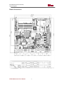


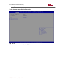

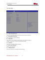
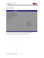


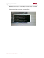


![User Guide [ ] - American Industrial Systems, Inc.](http://vs1.manualzilla.com/store/data/005740554_1-2a4ebbae5daccebd80088e03c7d32b9b-150x150.png)