1
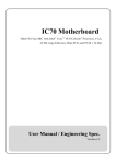
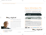
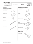
®
Extender for
DVI and RS232
Over
One Fiber Optic Cable
EXT-DVIRS232-1FO
User Manual
www.gefen.com
ASKING FOR ASSISTANCE
Technical Support:
Telephone
Fax
(818) 772-9100
(800) 545-6900
(818) 772-9120
Technical Support Hours:
8:00 AM to 5:00 PM Monday thru Friday Pacific Time
Write To:
Gefen, LLC
c/o Customer Service
20600 Nordhoff St
Chatsworth, CA 91311
www.gefen.com
[email protected]
Notice
Gefen, LLC reserves the right to make changes in the hardware, packaging and
any accompanying documentation without prior written notice.
Extender for DVI and RS232 Over One Fiber Optic Cable
is a trademark of Gefen, LLC
© 2011 Gefen, LLC, All Rights Reserved
All trademarks are the property of their respective owners.
Rev A2
CONTENTS
1
Introduction
2
Operation Notes
3
Features
4
Sender unit Layout
5
Sender unit Descriptions
6
Receiver unit Layout
7
Receiver unit Descriptions
8
Connecting the Extender for DVI and RS232 Over One Fiber Optic Cable
8
Wiring Diagram
9
DIP Switch Configuration
9
Sender Unit
11
Receiver Unit
12 Calibration Procedure
12
Calibrating the Sender unit and Receiver unit
12
Troubleshooting Procedure
13 RS-232 Serial Control
14 Specifications
15 Warranty
INTRODUCTION
Congratulations on your purchase of the Extender for DVI and RS232 Over One
Fiber Optic Cable. Your complete satisfaction is very important to us.
Gefen
Gefen delivers innovative, progressive computer and electronics add-on solutions
that harness integration, extension, distribution and conversion technologies.
Gefen’s reliable, plug-and-play products supplement cross-platform computer
systems, professional audio/video environments and HDTV systems of all sizes
with hard-working solutions that are easy to implement and simple to operate.
The Gefen Extender for DVI and RS232 Over One Fiber Optic Cable
The Extender for DVI and RS232 over One Fiber Optic cable is a complete
solution allowing DVI and RS-232 to be extended to a monitor, touch-screen
display, or other DVI device up to 1640 feet (500 meters) from the source.
A single strand SC fiber optic cable is used for the long distance extension,
providing excellent protection from background electromagnetic interference
(EMI), preserving both DVI and RS-232 signal integrity. Locking DVI, RS-232,
and power connectors ensure secure connections.
How It Works
The Sender unit is placed near the DVI source and the Receiver unit near the
Display. Connect the supplied DVI cable between the Sender unit and the DVI
source. Connect a second DVI cable between the Receiver unit and the display.
Connect the RS-232 cable from the RS-232 source to the Sender unit. Connect
the RS-232 cable between the Receiver unit and the RS-232 connection on the
display side. Connect a single strand of multi-mode SC-terminated fiber optic
cable between the Sender and Receiver unit. Connect the power supplies to both
the Sender and Reciever unit.
1
OPERATION NOTES
READ THESE NOTES BEFORE INSTALLING OR
OPERATING THE EXTENDER FOR DVI AND RS232 OVER ONE FIBER
OPTIC CABLE
•
When HDCP content is passed-through, DVI can only be extended up to
1000 feet (300 meters).
•
RS-232 data is bi-directional for direct commands and echo function or
status information. See page 13 for information on RS-232 settings.
IMPORTANT: Before connecting the power supplies to the Sender unit
and the Receiver unit, see page 12 for information on calibrating the
Extender.
•
When changing fiber optic cables, the calibration procedure must be
repeated.
2
FEATURES
Features
•
Extends DVI up to 1640 feet (500 meters)
•
Supports HD resolutions up to 1080p Full HD
•
Supports VESA resolutions up to 1920 x 1200
•
RS-232 port for automation
•
Locking power supplies
Package Includes
(1) Sender unit (EXT-DVIRS232-1FOS)
(1) Receiver unit (EXT-DVIRS232-1FOR)
(1) 6 ft. Dual Link DVI cable (CAB-DVIC-DL-06MM)
(1) 6 ft. RS-232 cable (CAB-DB9-6MF)
(2) 5V / 2A DC Locking Power Supplies (EXT-PS52AULP)
(1) Quick-Start Guide
3
SENDER UNIT LAYOUT
Front
2
3
4
1
Back
5
6
4
SENDER UNIT DESCRIPTIONS
1
P (Power Indicator)
This two-color LED will turn bright red once the included 5V DC locking power
supply has been properly connected to the unit and the locking power supply
has been connected to an available wall outlet. This LED will turn bright green
once the Sender unit and Receiver unit are communicating correctly.
2
C (Calibration Indicator)
This LED will alternate from red to green during the calibration procedure. The
LED will turn solid green once the calibration procedure has been completed.
See page 12 for more information on the calibration procedure.
3
DVI In
Connect a computer or other DVI source to this DVI port.
4
RS-232
Connect an RS-232 cable from this port to the controlling device.
5
Fiber
This connector accepts a single strand of SC-terminated fiber optic cable that
will link the Sender unit and Receiver unit together. The Gefen Extender for DVI
and RS232 Over One Fiber Optic Cable will only accept multi-mode fiber optic
cables.
6
5V DC
Connect the included 5V DC Locking Power Supply to this receptacle.
5
RECEIVER UNIT LAYOUT
Front
1
2
3
4
Back
5
6
6
RECEIVER UNIT DESCRIPTIONS
1
RS-232
Connect an RS-232 cable from this port to the RS-232 device.
2
DVI Out
Connect a DVI display to this DVI port.
Calibration Indicator
This LED will alternate from red to green during the calibration procedure. The
LED will turn solid green once the calibration procedure has been completed.
See page 12 for more information on the calibration procedure.
3
Power Indicator
This two-color LED will turn bright red once the included 5V DC locking power
supply has been properly connected to the unit and the locking power supply
has been connected to an available wall outlet. This LED will turn bright green
once the Sender unit and Receiver unit are communicating correctly.
4
5V DC Locking Power Connector
Connect the included 5V DC Locking Power Supply to this receptacle.
5
Fiber Optic Connector (SC-Type)
This connector accepts a single strand of SC-terminated fiber optic cable that
will link the Sender unit and Receiver unit together. The Gefen Extender for DVI
and RS232 Over One Fiber Optic Cable will only accept multi-mode fiber optic
cabling.
7
CONNECTING THE EXTENDER FOR DVI AND RS232
OVER ONE FIBER OPTIC CABLE
How to Connect the
Extender for DVI and RS232 Over One Fiber Optic Cable
1.
Connect the computer (or other DVI source) to the Sender unit using the
included Locking Dual Link DVI cable.
2.
Connect the DVI display to the Receiver unit using a Dual Link DVI cable.
3.
Connect an SC-terminated fiber optic cable to the Sender unit. Connect the
opposite end of the fiber cable to the Receiver unit.
4.
OPTIONAL: Connect an RS-232 cable from the RS-232 serial port on the
controlling device to the RS-232 port on the Sender unit. Connect another
RS-232 serial cable from the RS-232 port on the Receiver unit to the RS-232
port of the RS-232 device.
IMPORTANT: Before connecting the power supplies to the Sender unit
and the Receiver unit, see page 12 for information on calibrating the
Sender unit and Receiver unit.
Wiring Diagram for the
Extender for DVI and RS232 Over One Fiber Optic Cable
FIBER OPTIC CABLE
RS-232 CABLE
(Up to 1640 ft)
DVI CABLE
Computer
Receiver
Sender
d
DVI Display
EXT-DVIRS232-1FO
ATTENTION: This product should always be connected to a grounded
electrical socket.
8
DIP SWITCH CONFIGURATION
DIP Switches
On the bottom of the Sender unit and Receiver unit are a bank of four (4) DIP
switches. These DIP switches provide control over EDID, Deep Color, and unit
Calibration.
It may be necessary to remove the strip of tape to expose the DIP switches.
To change the DIP switch settings, move the appropriate DIP switch to its ON or
OFF position using a small pointed object. The DIP switches and their functions
are shown below.
Sender unit
DIP 1 - EDID Mode
•
OFF - Local EDID
When Local EDID mode is used, the EDID will be assembled by copying
all video and audio features of the connected device. Deep Color support
will be manually controlled: If Deep Color is supported by the display(s),
DIP 2 should be set to the ON position (see DIP 2 - Deep Color, below). By
default, the unit is shipped with DIP 1 in the OFF position.
•
ON - Pass-Through EDID
Allows all video and audio features of the connected devices to be passed to
the source device without control over Deep Color.
9
DIP SWITCH CONFIGURATION
DIP 2 - Deep Color
NOTE: DIP switch 2 is only functional when DIP switch 1 is set to the
OFF position.
•
OFF - Enables Deep Color support (12-bit color)
Enables Deep Color support. In Pass-through EDID Mode, setting DIP 2 to
the OFF position has no effect since all EDID information is passed through.
•
ON - Forces 8-bit Color
Disables Deep Color in the EDID. Deep Color management is only available
when Local EDID is being used.
DIP 3 - Calibration Mode
•
OFF - Enables Calibration Mode
Enables Calibration Mode. Make sure to set DIP switch 3 on both the
Sender unit and Receiver unit when calibrating the Extenders. See page 12
for details.
•
ON - Calibration Mode Lock
Locks the calibration settings. Set DIP switch 3 on both the Sender unit and
Receiver unit to the ON position after the calibration process has completed.
See page 12 for details on the calibration process.
10
DIP SWITCH CONFIGURATION
Receiver unit
DIP 1 - Not Used
•
Reserved for future expansion.
DIP 2 - Not Used
•
Reserved for future expansion.
DIP 3 - Calibration Mode
•
OFF - Enables Calibration Mode
Enables Calibration Mode. Make sure to set DIP switch 3 on both the
Sender unit and Receiver unit when calibrating the Extenders.
•
ON - Calibration Mode Lock
Locks the calibration settings. Set DIP switch 3 on both the Sender unit and
Receiver unit to the ON position after the calibration process has completed.
11
CALIBRATION PROCEDURE
Calibrating the Sender unit and Receiver unit
IMPORTANT: Before beginning the calibration process, make sure that
the Sender unit and Receiver are not powered.
1.
Make sure DIP switch 3 on both the Sender unit and the Receiver unit are in
the OFF position (see pages 9 and 11).
2.
Connect one end of the fiber cable to the Sender unit. Connect the other
end of the fiber cable to the Receiver unit.
3.
Connect the 5V DC Locking Power Supplies to the Sender unit and the
Receiver unit. Do not overtighten the locking connectors. Plug the power
cord into an available electrical outlet.
The LED indicators on both the Sender unit and Receiver unit will alternate from
red to green during the calibration process. The calibration process can take up
to 120 seconds to complete.
After the calibration process has finished, the LED indicators on both the Sender
unit and the Receiver unit will turn solid green. Set DIP switch 3 to the ON
position on both the Sender unit and the Receiver unit to lock the calibration settings.
NOTE: If the fiber optic cable is changed, follow steps 1 - 3 to repeat the
calibration procedure.
Troubleshooting
•
If the Sender unit and Receiver unit did not complete the calibration process,
the indicator LEDs on both Sender unit and Receiver unit will be red. Check
the fiber connections carefully and cycle the power on both the Sender unit
and the Receiver unit and repeat the calibration procedure.
•
When the indicator LED at one unit is GREEN and the other is RED,
cycle power on the unit with the RED indicator. It is also recommended to
cycle power on both the Sender unit and the Receiver unit to perform a full
calibration.
•
If the calibration procedure continues to fail, contact Gefen Technical
Support under the Asking For Assistance section at the beginning of this
manual.
12
RS-232 SERIAL CONTROL
54321
12345
9876
6789
Only Pins 2 (RX), 3 (TX), and 5 (Ground) are used on the RS-232 serial interface
RS232 Settings
g
Bits per second ............................................................................................ 19200
Data bits ............................................................................................................... 8
Parity ............................................................................................................. None
Stop bits ................................................................................................................1
Flow Control .................................................................................................. None
13
SPECIFICATIONS
Maximum Pixel Clock................................................................................ 165 MHz
Input Video Signal................................................................................ 1.2 Volts p-p
Input DDC Signal........................................................................... 5 volts p-p (TTL)
DVI Input Connectors.................................... (1) DVI-I, 29-pin, female (digital only)
Link Connector............................................................................................ SC fiber
Power Supply................................................................................................ 5V DC
Power Consumption.......................................................... 10 Watts per unit (max.)
Operating Temp....................................................................................... 0° - 40° C
Dimensions....................................................................... 3.4” D x 5.0” W x 1.25” H
Shipping Weight.............................................................................................. 4 lbs.
14
WARRANTY
Gefen warrants the equipment it manufactures to be free from defects in material
and workmanship.
If equipment fails because of such defects and Gefen is notified within two (2)
years from the date of shipment, Gefen will, at its option, repair or replace the
equipment, provided that the equipment has not been subjected to mechanical,
electrical, or other abuse or modifications. Equipment that fails under conditions
other than those covered will be repaired at the current price of parts and labor in
effect at the time of repair. Such repairs are warranted for ninety (90) days from
the day of reshipment to the Buyer.
This warranty is in lieu of all other warranties expressed or implied, including
without limitation, any implied warranty or merchantability or fitness for any
particular purpose, all of which are expressly disclaimed.
1.
Proof of sale may be required in order to claim warranty.
2.
Customers outside the US are responsible for shipping charges to and from
Gefen.
3.
Copper cables are limited to a 30 day warranty and cables must be in their
original condition.
The information in this manual has been carefully checked and is believed to
be accurate. However, Gefen assumes no responsibility for any inaccuracies
that may be contained in this manual. In no event will Gefen be liable for
direct, indirect, special, incidental, or consequential damages resulting from
any defect or omission in this manual, even if advised of the possibility of such
damages. The technical information contained herein regarding the features and
specifications is subject to change without notice.
For the latest warranty coverage information, refer to the Warranty and Return
Policy under the Support section of the Gefen Web site at www.gefen.com.
PRODUCT REGISTRATION
Please register your product online by visiting the Register Product page
under the Support section of the Gefen Web site.
15
Rev A2
20600 Nordhoff St., Chatsworth CA 91311
1-800-545-6900
818-772-9100
www.gefen.com
Pb
This product uses UL listed power supplies.
fax: 818-772-9120
[email protected]