1
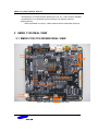
SMDK-C100_USER’S MANUAL_REV 0.00 Preliminary User’s Manual (SMDK-C100 Rev0.0) S5PC100X RISC Microprocessor October 15, 2008 REV 0.0 SMDK-C100_USER’S MANUAL_REV 0.00 Important Notice The information in this publication has been carefully checked and is believed to be entirely accurate at the time of publication. Samsung assumes no responsibility, however, for possible errors or omissions, or for any consequences resulting from the use of the information contained herein. Samsung reserves the right to make changes in its products or product specifications with the intent to improve function or design at any time and without notice and is not required to update this documentation to reflect such changes. This publication does not convey to a purchaser of semiconductor devices described herein any license under the patent rights of Samsung or others. Samsung makes no warranty, representation, or guarantee regarding the suitability of its products for any particular purpose, nor does Samsung assume any liability arising out of the application or use of any product or circuit and specifically disclaims any and all liability, including without limitation any consequential or incidental damages. "Typical" parameters can and do vary in different applications. All operating parameters, including "Typicals" must be validated for each customer application by the customer's technical experts. Samsung products are not designed, intended, or authorized for use as components in systems intended for surgical implant into the body, for other applications intended to support or sustain life, or for any other application in which the failure of the Samsung product could create a situation where personal injury or death may occur. Should the Buyer purchase or use a Samsung product for any such unintended or unauthorized application, the Buyer shall indemnify and hold Samsung and its officers, employees, subsidiaries, affiliates, and distributors harmless against all claims, costs, damages, expenses, and reasonable attorney fees arising out of, either directly or indirectly, any claim of personal injury or death that may be associated with such unintended or unauthorized use, even if such claim alleges that Samsung was negligent regarding the design or manufacture of said product S5PC100X RISC Microprocessor SMDK_C100 User’s manual, Revision 1.00 Copyright © 2008 Samsung Electronics Co.,Ltd. All rights reserved. No part of this publication may be reproduced, stored in a retrieval system, or transmitted in any form or by any means, electric or mechanical, by photocopying, recording, or otherwise, without the prior written consent of Samsung Electronics Co.,Ltd. Samsung Electronics Co., Ltd. San #24 Nongseo-Dong, Giheung-Gu Yongin-City Gyeonggi-Do, Korea 446-711 Home Page: http://www.samsungsemi.com/ E-Mail: [email protected] Printed in the Republic of Korea SMDK-C100_USER’S MANUAL_REV 0.00 Revision History Rev. No Description of Change 0.00 - Initial Release (SMDK_C100 Rev0.00) Refer to Author(s) J.K. RYOO Effective Date (MM/DD/YY) October, 15,2008 SMDK-C100_USER’S MANUAL_REV 0.00 Table of Contents 1 2 3 4 5 INTRODUCTION ............................................................................................7 1.1 SYSTEM OVERVIEW......................................................................................................... 7 1.2 SMDK C100 FEATURES .................................................................................................... 9 SMDK C100 REAL VIEW ................................................................................. 10 2.1 SMDK C100 CPU BOARD REAL VIEW ..........................................................................10 2.2 SMDK C100 BASE BOARD REAL VIEW........................................................................11 2.3 SMDK C100 LCD BOARD REAL VIEW..........................................................................14 CIRCUIT DESCRIPTION .................................................................................. 15 3.1 POWER DISTRIBUTION TREE ........................................................................................15 3.2 FUNCTIONAL BLOCK DIAGRAM..................................................................................17 SMDK C100 SYSTEM CONFIGURATIONS ............................................................... 18 4.1 PLL CLOCK SOURCE SELECTION.................................................................................19 4.2 BOOT MODE SELECTION ...............................................................................................19 4.2.1 Switch Configuration..................................................................................................19 4.3 CONFIGURATION SWITCH DESCRIPTION IN CPU BOARD .....................................20 4.3.1 CFGB3: FOR USING Controllable Regulator (ARM/INT)........................................20 4.3.2 CFG1: SELECTION FOR MAIN POWER SUPPLY ...............................................21 4.3.3 CFGB1: HDMI I2C Channel......................................................................................21 4.3.4 CFGB2: SELECTION BETWEEN CAM-A AND MMC1/2....................................21 4.4 CONFIGURATION SWITCH DESCRIPTION IN BASE BOARD...................................22 CFGB1: SROM BANK0 CHIP SELECTOR ..............................................................22 4.4.1 4.4.2 CFGB2: SROM BANK1 CHIP SELECTOR ..............................................................22 4.4.3 CFGB3: SROM BANK2 CHIP SELECTOR ..............................................................22 4.4.4 CFGB4: SROM BANK3 CHIP SELECTOR ..............................................................23 4.4.5 CFGB5: SROM BANK4 CHIP SELECTOR ..............................................................23 4.4.6 CFG8: CF CARD TRANSFER MODE SELECTOR .................................................23 4.4.7 CFG1: COM PORT CONTROL .................................................................................24 4.4.8 CFG2: KEYPAD/ CAM B CONTROL......................................................................24 4.4.9 CFG3: KEYPAD/ CAN2.0 CONTROL .....................................................................24 4.4.10 CFG4: S/PDIF SELECTOR ........................................................................................24 4.4.11 CFG5: WM8580 MASTER CLOCK SELECTOR .....................................................25 4.4.12 CFG6: AUDIO CONNECTOR ...................................................................................25 4.4.13 CFG7: AUDIO SELECTOR .......................................................................................25 4.5 JUMPER SETTING CONFIGURATION ...........................................................................26 Appendix : CONNECTORS ............................................................................. 28 5.1 CPU BOARD.......................................................................................................................28 5.1.1 JTAG ...........................................................................................................................28 5.1.2 USB .............................................................................................................................28 5.1.3 SPI ...............................................................................................................................29 5.1.4 MIPI HSI .....................................................................................................................29 5.1.5 SD host (Ver2.0) /MMC interface ...............................................................................30 5.1.6 EXTERNAL ONE-NAND connector..........................................................................31 5.1.7 Camera Interface –A Connector ..................................................................................32 5.1.8 PMIC connector...........................................................................................................33 5.1.9 HDMI Connector .........................................................................................................33 5.1.10 MIPI-CSI .....................................................................................................................34 5.1.11 MIPI-DSI ...................................................................................................................35 5.1.12 TFT LCD I/F CONNECTOR ......................................................................................35 5.2 BASE BOARD ....................................................................................................................37 5.2.1 Component, Composite & S-VIDEO Connector .........................................................37 5.2.2 LINE IN, MIC IN & SPEAKER OUT Connector.......................................................37 5.2.3 ETHERNET CONNECTOR .......................................................................................38 5.2.4 UART interface ...........................................................................................................38 SMDK-C100_USER’S MANUAL_REV 0.00 6 7 5.2.5 xD Picture Card Connector..........................................................................................39 5.2.6 CF Card Slot ................................................................................................................40 5.2.7 PWM connector ...........................................................................................................40 5.2.8 Camera Interface- B.....................................................................................................40 5.2.9 CAN 2.0 Interface........................................................................................................41 5.2.10 S/PDIF 5.1 Channel Audio Interface ..........................................................................42 5.3 EXTERNAL CONNECTOR INTERFACE ........................................................................43 5.3.1 ROM BUS Interface ....................................................................................................43 5.3.2 HOST/MODEM INTERFACE....................................................................................44 5.3.3 EXTERNAL KEYPAD CONNECTOR......................................................................45 5.3.4 MODULE1: FOR GPS DAUGHTER BOARD ..........................................................46 5.3.5 MODULE2: FOR MOBILE TV, HD RADIO DAUGHTER BOARD.......................47 5.3.6 MODULE3: FOR BLUETOOTH DAUGHTER BOARD..........................................47 5.3.7 MODULE4: FOR AUDIO DAUGHTER BOARD.....................................................48 5.3.8 MODULE5: FOR LCD BOARD (with Touch Screen)...............................................49 SMDK SCHEMATIC REVISION HISTORY ................................................................ 51 SMDK SCHEMATIC ....................................................................................... 52 SMDK-C100_USER’S MANUAL_REV 0.00 Figure List Figure 1 S5PC100X Functional Block Diagram..............................................................8 Figure 2 S5PC100X CPU BOARD TOP VIEW ................................................................ 10 Figure 3 S5PC100X CPU BOARD BOTTOM VIEW........................................................... 11 Figure 5 S5PC100X BASE BOARD BOTTOM VIEW.......................................................... 13 Figure 6 S5PC100X LCD BOARD TOP VIEW ................................................................ 14 Figure 7 S5PC100X LCD BOARD BOTTOM VIEW........................................................... 14 Figure 8 S5PC100X BASE BOARD POWER DISTRIBUTION TREE ......................................... 15 Figure 9 S5PC100X CPU BOARD POWER DISTRIBUTION TREE .......................................... 16 Figure 10 S5PC100X SMDK FUNCTIONAL BLOCK DIAGRAM.............................................. 17 Figure 11 JTAG Connector .................................................................................. 28 Figure 12 One USB ports & OTG port...................................................................... 29 Figure 13 SPI port ............................................................................................ 29 Figure 14 MIPI-HSI port ...................................................................................... 30 Figure 15 SD/MMC port ...................................................................................... 30 Figure 16 MMC port .......................................................................................... 31 Figure 17 One NAND memory port......................................................................... 32 Figure 18 Camera Interface -A port ....................................................................... 32 Figure 19 PMIC Connector................................................................................... 33 Figure 24 Component, Composite & S-VIDEO Connector............................................... 37 Figure 26 100Base-T Ethernet Socket ..................................................................... 38 Figure 27 UART Sockets ..................................................................................... 39 SMDK-C100_USER’S MANUAL_REV 0.00 1 INTRODUCTION 1.1 SYSTEM OVERVIEW SMDK_C100 (_C100 Development Kit) is a platform for code development of SAMSUNG's S5PC100X 16/32-bit RISC microcontroller (ARM-CORTEX A8). S5PC100X is used in hand-held devices and general applications. The S5PC100X is a 32-bit RISC cost-effective, low power, high performance microprocessor solution for mobile phones and general applications, and integrates an ARM Cortex-A8 which implements the ARM architecture V7-A with numerous peripherals to support. To provide optimized H/W performance for the 3G & 3.5G communication services, S5PC100X adopts 64-bit internal bus architecture and includes many powerful hardware accelerators for tasks such as motion video processing, display control and scaling. Integrated Multi Format Codec (MFC) supports encoding and decoding of MPEG-1/2/4, H.263, H.264 and decoding of VC1, Divx. This Hardware accelerators support real-time video conferencing and Analog TV out, HDMI for NTSC and PAL mode The S5PC100X has an optimized interface to external memory capable of sustaining the demanding memory bandwidths required in high-end communication services. The memory system has Flash/ROM external memory ports for parallel access and DRAM port for high bandwidth. DRAM port can be configured to support DDR2,mobile-DDR(LPDDR1) or LPDDR2. Flash/ROM Port supports NAND Flash, NOR-Flash, OneNAND and ROM type external memory. To reduce total system cost and enhance overall functionality, S5PC100X includes many hardware peripherals such as TFT 24-bit true color LCD controller, Camera Interface, MIPI DSI, CSI-2 and HSI, System Manager for power management, CF+, ATA I/F, 4-channel UART, 24channel DMA, 4-channel Timers, General I/O Ports, 3-ch IIS, 2-ch S/PDIF, 2-ch CAN bus, IICBUS interface, 3-ch HS-SPI, USB Host 2.0, USB OTG 2.0 operating at high speed (480Mbps), SD Host & High Speed Multi-Media Card Interface and PLLs for clock generation. POP (Package on Package) option with MCP is available for small form factor applications. The SMDK_C100 consists of S5PC100X, bootable (NAND, OneNAND, NOR FLASH), LCD interface, two serial communication ports, configuration switches, JTAG interface, status LEDs and etc. SMDK-C100_USER’S MANUAL_REV 0.00 Figure 1 S5PC100X Functional Block Diagram SMDK-C100_USER’S MANUAL_REV 0.00 1.2 SMDK C100 FEATURES The SMDK_C100 (S5PC100X Development Kit) highlights the basic system-based hardware design which uses the S5PC100X. It can evaluate the basic operations of the S5PC100X and assist in developing codes. SMDK_C100 is manufactured by MERITECH Co., Ltd and company website is www.mcukorea.com The features of SMDK_C100 include: - Microcontroller : S5PC100X (16/32 bit RISC microcontroller, ARM-CORTEX A8 ) - - System Boot Device : . Internal ROM (i-ROM) . AMD 8Mbit NOR Flash 1EA (support halfword size boot ROM) . SAMSUNG NAND Flash 1EA (with Socket) . SAMSUNG OneNAND 1EA (External Board Option) . SAMSUNG 8Mbit SRAM 1EA . Modem Boot (External Connector) SDRAM : Memory Port-1: 256MB mDDR (128MB x 2, K4X1G163PC-L(F)E/GC6) Note : Memory Port0: None (* Port 0 Bus is only for Static Memory Interface) - TFT LCD & Touch panel interface : Upto Resolution 1024 X 768 Compact FLASH / ATA interface SD/SDIO/MMC interface (Socket x 2) Digital Video & Audio : HDMI 1.3 Video(720p) & S/PDIF 5.1 Channel Audio I/F TV Out interface (Component, S-Video, Composite,) - USB Host , USB OTG 2.0 interface High Speed SPI interface - IIS/AC97/PCM Interface : WM9713, WM8580 For Audio CODEC General Camera Interface : Port-A and Port-B MIPI Camera Interface : MIPI-CSI2 (1Gbps/Lane Serial Communication) High Speed Serial MIPI Interface LCD : MIPI-DSI (1Gbps/Lane Serial Communication) High Speed MODEM Serial Interface : MIPI-HSI 2 port CAN interface : Ver.2.0 Keypad interface Ethernet Interface : 10/100Mbps - 2 port UART interface JTAG port - Module Connector (M1 ~ M5) . M1 (Module1): For GPS Daughter Board (UART0, SPI0) : Samsung GPD14B01 (SiRFSTAR III GSD3) (Optional) . M2 (Module2): For Mobile TV Daughter Board (SPI1, IIC) or For HD Radio (SPI1, IIS for Module4) Mobile TV: Samsung S5P4F31 (TBD, Optional) HD Radio: SiPORT SD1010 (TBD, Optional) , Samsung (TBD, Optional) . M3 (Module3): For Bluetooth Daughter Board (UART1, PCM for PMIC Audio Codec) : Bluetooth: Atheros (TBD, Optional) SMDK-C100_USER’S MANUAL_REV 0.00 . M4 (Module4): For Audio Daughter Board (AC97, IIS, IIC) : Audio: Wolfson WM8990 . M5 (Module5): For LCD Module: Samsung WVGA 4.8” (Default), WSVGA, QVGA(Optional) . PMIC (200-FBGA Connector) : National Semiconductor PMIC(TBD, Optional) 2 SMDK C100 REAL VIEW 2.1 SMDK C100 CPU BOARD REAL VIEW 5V/3A JTAG SPI USB USB-OTG POWER ON/OFF HDMI MIPI-CSI MIPIDSI DRAM OneDRAM I/F CFGB2 MIPIHSI CFGB3 S5PC100 POWER JUMPER LEVEL SHIFTER LCD I/F VRM@ARM VRM@INT BATTERY CONNECTOR PMIC SELECTION SW CAMERA-A Port RESET Figure 2 S5PC100X CPU BOARD TOP VIEW SMDK-C100_USER’S MANUAL_REV 0.00 SD/MMC #1 OSC1:12MHz@PLL X2:12MHz@PLL X1:48MHz@USB-HOST X3:32.768KHz@RTC X4:27MHz@DAC SD/MMC #2 PMIC SOCKET Figure 3 S5PC100X CPU BOARD BOTTOM VIEW 2.2 SMDK C100 BASE BOARD REAL VIEW SMDK-C100_USER’S MANUAL_REV 0.00 Component Video IrDA AUDIO PORT Camera B-Port B2B CONNECTOR For CPU Board GPS Mobile-TV Bluetooth Audio MODEM I/F NAND NOR GPS ROM Bus Connector XD-Picture Card Figure 4 S5PC100X BASE BOARD TOP VIEW SMDK-C100_USER’S MANUAL_REV 0.00 UART SPI Composite Video LAN S/PDIF Audio CODEC 100BaseT MAC CAN 2.0 QWERTY KEYPAD Compact Flash Figure 5 S5PC100X BASE BOARD BOTTOM VIEW SMDK-C100_USER’S MANUAL_REV 0.00 2.3 SMDK C100 LCD BOARD REAL VIEW 4.8” 800 x 480 WVGA 4.8” 1024 x 600 WSVGA 2.2” 240 x 320 QVGA Figure 6 S5PC100X LCD BOARD TOP VIEW LVDS Transmitter (For WSVGA) Figure 7 S5PC100X LCD BOARD BOTTOM VIEW SMDK-C100_USER’S MANUAL_REV 0.00 3 CIRCUIT DESCRIPTION The SMDK_C100 is designed to test S5PC100X and develop software while hardware is being developed. Figure 10 highlights the SMDK_C100's block diagram. 3.1 POWER DISTRIBUTION TREE SMDK_C100 is operated by 1.2V for Internal, 1.8V for Memory and 3.3V for Input/Output pad and several peripherals. SMDK_C100 is supplied by 5V/3A DC Adaptor Power. The SMDK_C100 has distributed power plane, with power going separately to the MCU and the main power plane. Figure 8 S5PC100X BASE BOARD POWER DISTRIBUTION TREE SMDK-C100_USER’S MANUAL_REV 0.00 Figure 9 S5PC100X CPU BOARD POWER DISTRIBUTION TREE SMDK-C100_USER’S MANUAL_REV 0.00 3.2 FUNCTIONAL BLOCK DIAGRAM Figure 10 S5PC100X SMDK FUNCTIONAL BLOCK DIAGRAM SMDK-C100_USER’S MANUAL_REV 0.00 4 SMDK C100 SYSTEM CONFIGURATIONS Perform the following steps to use SMDK_C100 board: 1. Select the Clock source Please refer to ‘CLOCK SOURCE SELECTION’ 2. Set the Regulator mode (Fixed or Controllable voltage , VDD_ARM & VDD_INT) Please refer to ‘CONFIGURATION SWITCH DESCRIPTION IN CPU BOARD CFGB3’ , 3. Select the Boot mode and set by configuration switches ( There are 5 boot modes) Please refer to ‘BOOT MODE SELECTION’ 4. Set the each IP which you want to use by CPU and Base boards configuration switches - For MMC Please refer to ‘CONFIGURATION SWITCH DESCRIPTION IN CPU BOARD’ - For CF CARD, LCD, Audio Controller, Audio Port(IIS,AC97,PCM), UART, IrDA, KEYPAD, Host I/F Please refer to ‘CONFIGURATION SWITCH DESCRIPTION IN BASE BOARD’ 5. Check the Connector Please refer to ‘CONNECTORS’ , On Appendix - JTAG, HDMI,MIPI-CSI, MIPI-DSI,USB, HS-SPI, MIPI HSI, SD/MMC, External MMC & MOVI-NAND & CF-ATA, External OneNAND,Camera I/F-A,PMIC External ROM bus, External MODEM I/F On CPU Board - Component, Composite & S-video, S/PDIF, CAN2.0,Line in/ MIC in/ Speaker out, Ethernet, UART, Camera I/F-B, ADC, MMC, xD, PWM, External SPI, TFT LCD(NonMIPI), Touch screen, , External LCD, External KEYPAD(QWERTY), Module 1 ~ 5 On Base Board - Configuration Switch (DIP Switch) 1 ――→ 2 ――→ 3 ――→ 4 ――→ Off(Switch Open) → On (Switch Short) SMDK-C100_USER’S MANUAL_REV 0.00 4.1 PLL CLOCK SOURCE SELECTION EXTCLK or X-TAL can be selected for the S5PC100X system clock by setting the XOM[0] values. The Clock Source selection must be X-tal Clock (CFG2[1] on CPU Board). Description CFG2[1] , (XOM[0]) X-tal Clock (12 ~20MHz) OFF (Logic “0”) External Oscillator Clock (USB Clock) ON (Logic “1”) 4.2 BOOT MODE SELECTION 4.2.1 Switch Configuration A. Set CFG2 on CPU board to select Internal ROM Boot Description Internal ROM Boot for NAND Flash Internal ROM Boot for OneNAND Internal ROM Boot for Movi / i-NAND Internal ROM for (NOR) NOR FLASH (1st & 2ND BOOT) B. [5] OFF OFF OFF OFF OFF CFG2[5:1] [4] OFF OFF OFF OFF ON * CFG2[6] : N.C [3] OFF OFF ON ON X [2] OFF ON OFF ON X [1] OFF OFF OFF OFF OFF Set CFG3 on CPU board to select Description CFG3[4:1] [3] [2] [4] ☞ Case 1 : CFG2 : Internal ROM Boot for NAND Flash NAND Flash, 512-byte page, OFF 3 Addr. Cycle Normal NAND, 512-byte page, OFF 4 Addr. Cycle Large Page NAND, 2K-byte page, OFF 4 Addr. Cycle Large Page NAND, 2K-byte page, OFF 5 Addr. Cycle Large Page NAND, 4K-byte page, OFF 4 Addr. Cycle Large Page NAND, 4K-byte page, OFF 5 Addr. Cycle ☞ Case 2 : CFG2 : Internal ROM Boot for Movi / i-NAND Movi-NAND (MMC) OFF i- NAND (SD) OFF Description ECC Encryption No ECC Encryption [1] OFF OFF OFF ON OFF OFF OFF ON OFF OFF ON OFF ON ON ON ON ON ON X X X X OFF ON CFG[6:5] [6] x x [5] OFF ON SMDK-C100_USER’S MANUAL_REV 0.00 Use PLL No Use PLL OFF ON x x 4.3 CONFIGURATION SWITCH DESCRIPTION IN CPU BOARD 4.3.1 CFGB3: FOR USING Controllable Regulator (ARM/INT) CFGB3 Switch is used to enable shift register output. If the shift register is not enabled, the default value of the VDD_1.2V_ARM/INT is determined with external pull up/down resisters. Below is the description of the Regulator Control Signal. VID4 0 0 LTC3714 (U22-For ARM, U25-For INT) @ CFGB3[1]: ON & ‘XEINT4(GPH04)’ : Logic “0” VID3 VID2 VID1 1 0 0 1 0 1 VID0 1 0 Dynamic Voltage scaling 1.300V 1.250V 0 1 0 1 1 1.200V 0 0 0 1 1 1 1 1 1 0 0 1 0 1 0 1.150V 1.100V 1.050V 0 1 1 1 1 1.000V 1 1 1 0 0 0 0 0 0 0 0 1 0 1 0 0.975V 0.950V 0.925V 1 0 0 1 1 0.900V 1 1 1 0 0 0 1 1 1 0 0 1 0 1 0 0.875V 0.850V 0.825V 1 0 1 1 1 0.800V 1 1 1 1 1 1 0 0 0 0 0 1 0 1 0 0.775V 0.750V 0.725V 1 1 0 1 1 0.700V SMDK-C100_USER’S MANUAL_REV 0.00 4.3.2 CFG1: SELECTION FOR MAIN POWER SUPPLY 4.3.3 CFGB1: HDMI I2C Channel CFGB1 Description [1] OFF(Logic”0”): ENABLE [2] ON(Logic”1”): DISABLE N.C 4.3.4 CFGB2: SELECTION BETWEEN CAM-A AND MMC1/2 CFGB2 Description [1] [2] ON(Logic”0”) OFF(Logic”1”) MMC1 == MMC2 OFF(Logic”1”) OFF(Logic”1”) MMC1 == CAM-A, SMDK-C100_USER’S MANUAL_REV 0.00 4.4 CONFIGURATION SWITCH DESCRIPTION IN BASE BOARD 4.4.1CFGB1: SROM BANK0 CHIP SELECTOR CFGB1 component is used to select devices as SROM BUS I/F 0(B_M0CSnx). CFGB1 Description [3] [2] [1] NOR (AMD) Flash OFF OFF ON SRAM OFF ON OFF External Device ON OFF OFF 4.4.2CFGB2: SROM BANK1 CHIP SELECTOR CFGB2 component is used to select devices as SROM BUS I/F 1(B_M0CSn2/FCSn0). CFGB2 Description [4] [3] [2] [1] XD card OFF OFF OFF ON NAND OFF OFF ON OFF External Device OFF ON OFF OFF Ethernet ON OFF OFF OFF 4.4.3 CFGB3: SROM BANK2 CHIP SELECTOR CFGB3 component is used to select devices as SROM BUS I/F 2(B_M0CSn3/FCSn1). CFGB3 Description [4] [3] [2] [1] XD card OFF OFF OFF ON NAND OFF OFF ON OFF External Device OFF ON OFF OFF Ethernet ON OFF OFF OFF SMDK-C100_USER’S MANUAL_REV 0.00 4.4.4 CFGB4: SROM BANK3 CHIP SELECTOR CFGB4 component is used to select devices as SROM BUS I/F 3(B_Xm0CSn4/FCSn2/CFCSn0). CFGB4 Description [4] [3] [2] [1] SRAM OFF OFF OFF ON NAND Flash OFF OFF ON OFF CF Card OFF ON OFF OFF Ethernet ON OFF OFF OFF 4.4.5 CFGB5: SROM BANK4 CHIP SELECTOR CFGB5 component is used to select devices as SROM BUS I/F 4(B_Xm0CSn5/FCSn3/CFCSn1). CFGB5 Description [4] [3] [2] [1] SRAM OFF OFF OFF ON NAND Flash OFF OFF ON OFF CF Card OFF ON OFF OFF Ethernet ON OFF OFF OFF 4.4.6 CFG8: CF CARD TRANSFER MODE SELECTOR CFGB7 component is used to select CF transfer mode. CFG8 Description [2] [1] Direct Mode N.C OFF Indirect Mode N.C ON Note. * Direct Mode: Mode which has Control signal for CF through the dedicated CF pin * Indirect Mode: Mode which has Control signal for CF through the EBI SMDK-C100_USER’S MANUAL_REV 0.00 4.4.7 CFG1: COM PORT CONTROL CFG1 component is used to control COM Port. CFG1 Description [3] [2] [1] UART1 X X OFF UART2 OFF OFF ON UART3 ON ON ON IrDA(U2) OFF X X 4.4.8 CFG2: KEYPAD/ CAM B CONTROL CFG2 component is used to control Keypad. CFG2 Description [2] [1] Disable OFF OFF KEYPAD OFF ON CAMERA B ON OFF 4.4.9 CFG3: KEYPAD/ CAN2.0 CONTROL CFG3 component is used to control Keypad. CFG3 Description 4.4.10 [2] [1] Disable OFF OFF KEYPAD ON OFF CAN 2.0 ON ON CFG4: S/PDIF SELECTOR CFG4 component is used to SPDIF. CFG1 Description SMDK-C100_USER’S MANUAL_REV 0.00 4.4.11 [1] Channel-B1 [2] Channel-B2 CFG5: WM8580 MASTER CLOCK SELECTOR CFG5 component change source of WM8580 Master clock. CFG5 4.4.12 DESCRIPTION [1] CDCLK of I2S0 is source of WM8580 Master clock [2] CDCLK of I2S1,2 is source of WM8580 Master clock [3] CLOCK of External is source of WM8580 Master clock. CFG6: AUDIO CONNECTOR CFG6 component is used to select S5PC100X Audio port. Description CFG6 ON OFF WM9713(AC97) WM8580(IIS) - - [1] : Speaker [2] : Mic [3] : Line In [4] : Reserved 4.4.13 CFG7: AUDIO SELECTOR CFG7 component is used to select S5PC100X Audio port. Description CFG7 [1] [2] [3] ON OFF Audio1 Enable Audio1 Disable Audio1: Audio1: WM8580 WM9713 IIS/PCM AC97 Audio2 Enable Audio2 Disable SMDK-C100_USER’S MANUAL_REV 0.00 [4] Audio1: Audio1: WM8580 WM9713 IIS/PCM IIS/PCM 4.5 JUMPER SETTING CONFIGURATION J1: Alternative Chip selection (Flash CS0/ OneNAND CS0) z CS0 For Flash memory z CS0 For OneNAND J2: Alternative Chip selection (Flash CS1/ OneNAND CS1) z CS1 For Flash memory z CS1 For OneNAND J3: Level Shifter Power supply z VDD_SYS (3.3V) z z z VDD_MEM0 (1.8V) SMDK-C100_USER’S MANUAL_REV 0.00 J4: Alternative Chip Selection For SROM Memory Port 0 z CS0 z CS1 SMDK-C100_USER’S MANUAL_REV 0.00 5 Appendix : CONNECTORS 5.1 CPU BOARD 5.1.1 JTAG Figure 11 JTAG Connector Note. * 5.1.2 USB One USB ports A-type (CON7, HOST) and one USB OTG port mini AB-type (CON6) are supported by the SMDK_C100. SMDK-C100_USER’S MANUAL_REV 0.00 Figure 12 One USB ports & OTG port 5.1.3 SPI Two IEEE-1394 connectors are used as SPI connecter. Figure 13 SPI port 5.1.4 MIPI HSI FPC cable is used as a MIPI HSI connector SMDK-C100_USER’S MANUAL_REV 0.00 Figure 14 MIPI-HSI port 5.1.5 SD host (Ver2.0) /MMC interface SD/MMC is provided by the _C100 and SD card sockets are supported in the SMDK_C100. Figure 15 SD/MMC port SMDK-C100_USER’S MANUAL_REV 0.00 Figure 16 MMC port 5.1.6EXTERNAL ONE-NAND connector External connector is supported for connecting ONE_NAND external board SMDK-C100_USER’S MANUAL_REV 0.00 Figure 17 One NAND memory port 5.1.7 Camera Interface –A Connector SMDK_C100 provides Camera Interface Connector. Figure 18 Camera Interface -A port SMDK-C100_USER’S MANUAL_REV 0.00 5.1.8 PMIC connector SMDK_C100 provides 200-FBGA Connector for PMIC Module Board. Figure 19 PMIC Connector 5.1.9HDMI Connector SMDK-C100_USER’S MANUAL_REV 0.00 Figure 20 HDMI VIDEO CONNECTOR 5.1.10 MIPI-CSI Figure 21 MIPI-CSI port SMDK-C100_USER’S MANUAL_REV 0.00 5.1.11 MIPI-DSI Figure 22 MIPI-DSI port 5.1.12 TFT LCD I/F CONNECTOR SMDK-C100_USER’S MANUAL_REV 0.00 Figure 23 TFT-LCD CONNECTOR SMDK-C100_USER’S MANUAL_REV 0.00 5.2 BASE BOARD 5.2.1 Component, Composite & S-VIDEO Connector SMDK_C100 provides Component(Y-Pb-Pr), Composite(Y) & S-Video(Y/C) output connector Figure 24 Component, Composite & S-VIDEO Connector 5.2.2LINE IN, MIC IN & SPEAKER OUT Connector SMDK_C100 provides LINE IN, MIC IN and SPEAKER OUT as an audio connector. SMDK-C100_USER’S MANUAL_REV 0.00 Figure 25 Audio Line In, Mic In & Speaker Out Connector 5.2.3 ETHERNET CONNECTOR SMDK_C100 provides Ethernet 100Mbps (CON20) connector. Figure 26 100Base-T Ethernet Socket 5.2.4UART interface The S5PC100X UART unit provides three independent asynchronous serial I/O (SIO) ports including IrDA. In SMDK_C100 board, COM1 port is only used for UART0. No jumper setting is required. You SMDK-C100_USER’S MANUAL_REV 0.00 can change UART by setting related jumpers. Figure 27 UART Sockets 5.2.5xD Picture Card Connector SMDK_C100 provides xD Picture Card Connector. Figure 28 xD Picture Card Socket SMDK-C100_USER’S MANUAL_REV 0.00 5.2.6 CF Card Slot SMDK_C100 provides CF/ATA Card Slot Connector. Figure 1 CF CARD SLOT 5.2.7PWM connector 5.2.8 Camera Interface- B SMDK-C100_USER’S MANUAL_REV 0.00 Figure 2 Camera Interface –B Connector 5.2.9 CAN 2.0 Interface 그림 3 CAN2.0 port Figure 4 CAN 2.0 Port SMDK-C100_USER’S MANUAL_REV 0.00 5.2.10 S/PDIF 5.1 Channel Audio Interface Figure 5 S/PDIF Audio Port SMDK-C100_USER’S MANUAL_REV 0.00 5.3 EXTERNAL CONNECTOR INTERFACE 5.3.1 ROM BUS Interface Figure 6 ROM BUS INTERFACE SMDK-C100_USER’S MANUAL_REV 0.00 5.3.2 HOST/MODEM INTERFACE Figure 7 HOST/MODEM INTERFACE SMDK-C100_USER’S MANUAL_REV 0.00 5.3.3 EXTERNAL KEYPAD CONNECTOR Figure 8 External Keypad Connector SMDK-C100_USER’S MANUAL_REV 0.00 5.3.4 MODULE1: FOR GPS DAUGHTER BOARD Figure 9 MODULE1 : For GPS SMDK-C100_USER’S MANUAL_REV 0.00 5.3.5 MODULE2: FOR MOBILE TV, HD RADIO DAUGHTER BOARD Figure 10 MODULE2 : For MobileTV / HD Radio 5.3.6 MODULE3: FOR BLUETOOTH DAUGHTER BOARD SMDK-C100_USER’S MANUAL_REV 0.00 Figure 11 MODULE3 : For Bluetooth Module 5.3.7 MODULE4: FOR AUDIO DAUGHTER BOARD Figure 12 MODULE4 : For Audio Module SMDK-C100_USER’S MANUAL_REV 0.00 5.3.8 MODULE5: FOR LCD BOARD (with Touch Screen) TFT LCD controllers are equipped in the S5PC100X. TFT LCD, touch panel and LCD backlight driver are supported in the SMDK_C100. Part Name Default LCD Option #1 Option #2 Model Name LMS480KF02 LTS480WS-C01 LTS222QVF0 Pannel Size 4.8” 4.8” 2.2” #pixels 800x480 (WVGA) 1024x600 (WSVGA) 240x320 (QVGA) I/F type 24bit RGB 6bit/3Lane LVDS RGB Serial / I-80 Figure 13 4.8 inch WVGA LCD I/F SMDK-C100_USER’S MANUAL_REV 0.00 Figure 14 2.2 inch QVGA LCD I/F SMDK-C100_USER’S MANUAL_REV 0.00 Figure 15 4.8 inch WSVGA LCD I/F 6 SMDK SCHEMATIC REVISION HISTORY This document contains information of corrected points on the schematic of SMDK_C100. The corrected points are highlighted in pink-circled in schematic of SMDK_C100 Rev 0.1 Boards CPU Board Base Board LCD Board Page Contents Corrected points (ECN) SMDK-C100_USER’S MANUAL_REV 0.00 7 SMDK SCHEMATIC There are 3 parts of SMDK Schematic. 1. CPU Board Rev0.0 (SMC823A) 2. Base Board Rev0.0 (SMC824A) 3. LCD Board Rev0.0 (SMC825A) S5PC100_SM DK_ S5PC100_SM DK_ S5PC100_SM DK_ CPU_BD_SCHEM ABASE_BD_SCHEMLCD_DB_SCHEM A Note. It is easy to find schematic parts by using Bookmarks on PDF